Loading ...
Loading ...
Loading ...
Part number 550-100-211/0122
– 107 –
220 /29 9/3 00 /39 9
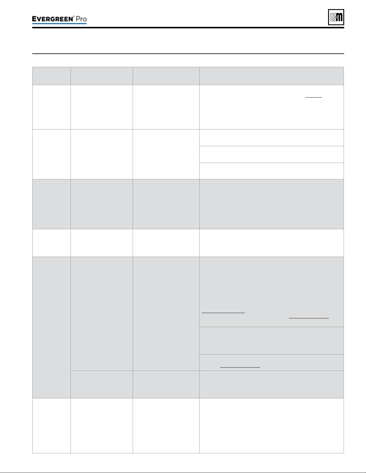
Figure103 Troubleshooting suggestions for Evergreen
®
boilers — Faultdisplays,diagnosticsandcorrectiveactions
(continued)
Display
Condition Diagnostics Corrective Action(s)
LOW WTR
CUTOFF OPEN
Occurs if internal low water
cutoff contacts open.
Automatic reset occurs if
contacts are open at least
one second, but less than
5 seconds.
Manual reset of control if
contacts are open longer
than 5 seconds.
Check for low water condition in system. Repair system as
necessary; refer to the piping section starting on page 39.
If low water condition does not exist, check Diagnostics — Inputs
screen to view status of Low Water Cutoff. If shown as OPEN
check wiring between LWCO and control. If wiring is ne, remove
LWCO and Clean probe. If problem still exist, then replace the
LWCO.
SUPPLY 58° F >
RETURN
Boiler Out temperature
has exceeded the Boiler In
temperature by more than
58º F.
Automatically resets after
30 second delay when
conditions no longer exist
or using manual reset on
display.
Verify water pipe is installed correctly per instructions in this
manual.
Verify proper circulator and speed for boiler size and system
requirements.
See message displayed TEMPERATURE SENSOR and follow
procedure for loose connections.
RETURN >
SUPPLY
Occurs if a return water
temperature is greater
than the corresponding
supply temperature by 10º
F or more.
Automatically resets when
condition no longer exists.
Verify proper ow direction of the boiler circulator.
Verify proper placement of system sensors for single or multiple
boiler system. System sensors should be on system piping not on
the boiler loop.
Verify sensors are wired to correct terminal locations.
System sensors may need to be located further away from the
boiler loop connection to the system, if proximity to the boiler loop
is causing sensors to be heated inaccurately.
SUPPLY WATER
TEMPERATURE
TOO HIGH
Occurs when the System
Supply temperature goes
above 200º F when the
burner is running.
Automatically resets when
Supply temperature goes
below 200º F.
Verify proper ow direction of the boiler circulator. This circulator
must be installed to push water through the system.
TEMPERATURE
SENSOR FAULT
Occurs if a temperature
sensor has electrically
shorted (SHORT) or has
become disconnected
(OPEN).
Will automatically reset if the
condition clears.
Check all the temperature readings of the boiler on the
DIAGNOSTICS - TEMPERATURES menu to determine if any
sensors are currently displayed as SHORT or OPEN. Compare
this to the boiler temperatures recorded in the DIAGNOSTICS -
ERRORS - LOCKOUT HISTORY # - TEMPERATURES during
the last several lockout conditions.
Determine which sensors are suspect and measure their
resistance value and compare it to the values shown in
Figure 99, page 103. If the resistance values are incorrect
replace the temperature sensor. Refer to Replacement parts for
proper part number.
Check wire harness for loose connections and pin engagement
at sensor connection, chassis mount connection through control
housing, and the control. Unplug connection at sensor and at
control and check continuity between ends.
If problem persists after checking items above, replace control.
Refer to Replacement parts for kit number.
Occurs if dual temperature
sensors values have
spread by more that 10º F
if the burner is on.
Automatically resets when
sensors are within 10º F.
Follow procedure for above for SHORT and OPEN sensor
conditions to properly diagnose sensor. If measured resistance
values of sensors convert to temperatures separated by more
than 10º F replace the sensor.
FLUE TEMP
TOO HIGH
Occurs if ue temperature
sensor exceeds 210º F
(Warning) or 220º F
(Lockout).
Automatic reset occurs if
temperature drops below
210º F for 2½ minutes.
Manual reset is required if
the temperature rises above
220° F. Reset using manual
reset screen on display.
Follow procedure for above for SHORT and OPEN sensor
conditions to properly diagnose sensor. In addition inspect heat
exchanger combustion chamber and ueways for abnormal wear
or buildup.
Inspect vent system for abnormal wear or damage.
Contact Weil-McLain Technical Support.
Loading ...
Loading ...
Loading ...