Loading ...
Loading ...
Loading ...
Part number 550-100-211/0122
– 58 –
(see wiring diagram, Figure 65, page 59)(continued)
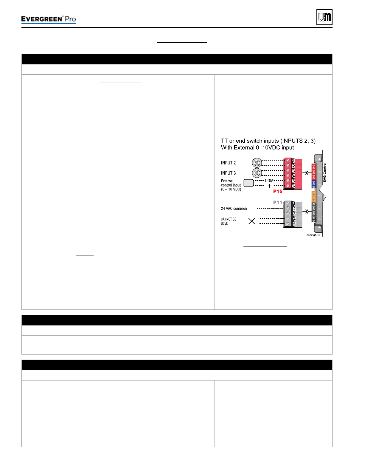
M. 0–10 VDC Remote MODULATION input – OPTIONAL
TerminalBlockP15#5(EVG control module, left side)
1. See illustration at right and Figure65,page59 for details.
2. is illustration also shows how to connect TT or end switch contacts at
INPUT2 and INPUT3 for other uses.
3. Note that using 0–10VDC input replaces INPUT1 for generating a heat
demand. Do not wire any input to INPUT1 as shown at right.
4. Remote modulation requires a 0–10VDC input signal at P15-4/5 as shown
at right.
a. e 0–10VDC input positive connection must be at terminal6 and com-
mon connection at terminal5.
5. Control setup:
a. Many options are available for conguring the control. e following is
a suggested setup that uses factory default settings as much as possible.
b. Default is BASIC in the Contractor menu.
c. If DHW is required, use PRIORITY1 to minimize setup steps.
y Connect the DHW aquastat to INPUT2 or INPUT3 and assign the
input used to PRIORITY1.
y Verify that control settings are suitable for the application, change
if necessary.
d. Use PRIORITY2 for the system to be remote modulated.
y e factory default settings for this priority are best suited for space
heating.
y Assign INPUT1 to the priority chosen. Accept all defaults for IN-
PUT1 — no changes should be necessary during the WIZARD.
y Aer the WIZARD has been completed, go to the ASSIGN INPUTS
menu for INPUT1. Change SOURCE to 0–10V (default setting is
TT1). See page78 for ASSIGN INPUTS menu information.
6. Operation:
a. e boiler comes on at 0.9VDC and turns o at 0.8VDC. 1VDC = 10%
input. 10VDC = 100% input. ese voltage settings are not adjustable.
b. OUTPUT1 (120VAC) is activated and deactivated as the heat demand is
turned on and o. is output is a good choice to operate the system pump.
7. NOTE: e EVG control can be congured to use either 0–10VDC for target
operation (see previous section) or modulation,
butnotboth.
See Figure65,page59 for details.
N. 120VAC Power Receptacle
Locatedonboilerrightsidepanel
1. Electrical rating is 2.0amps max at 120VAC.
2. is receptacle can be used to plug in a condensate pump.
O. Multiple Boiler and BMS Connections – see ADVANCED Manual
TerminalStripsP4andP5onPump/CommBoard(control tray, left side)
1. e boiler control is capable of multiple boiler communication and control
of up to eight Evergreen
®
boilers in one installation.
2. e boiler control is also capable of BMS communication.
3. e boiler control is also capable ZoneStacking
TM
:
Uses All boiler inputs, not just the rst and last boilers, up to 24 customiz-
able inputs across boiler network (3 per unit, maximum of 8 boilers on the
network).
4. See Evergreen
®
Advanced Manual for multiple boiler installation and setup
information.
See EVG Advanced Manual for details.
220 /29 9/3 00 /39 9
Loading ...
Loading ...
Loading ...