Loading ...
Loading ...
Loading ...
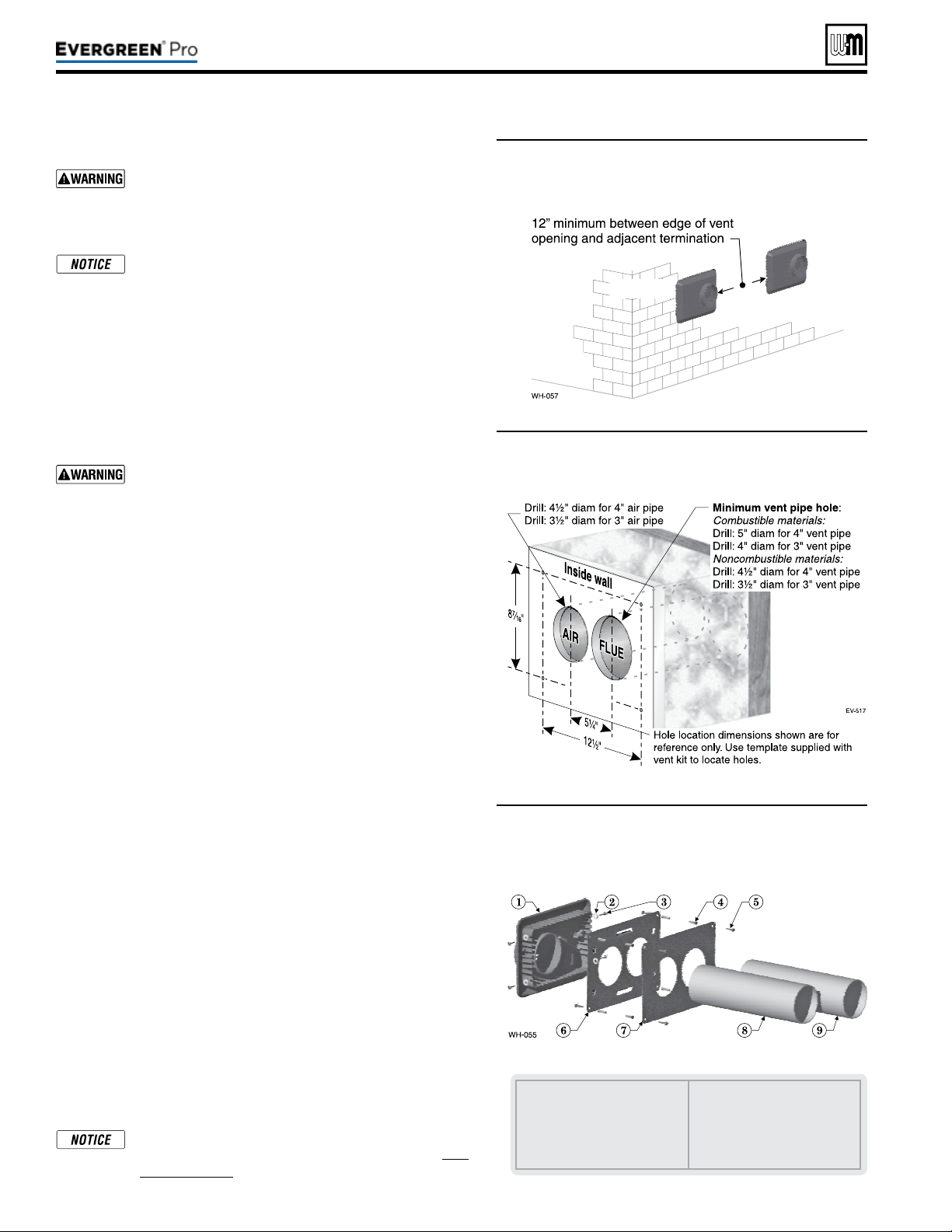
Figure31 Adjacent terminations — OUTSIDE VIEW
— clearance from air inlet to exhaust from
another appliance
DIRECT VEN T
(continued)
InstallWeil-McLainvent/aircap
ADAPTERS — Use adapters if using other than 4-inch
PVC or CPVC. is is required for dierent materials
(polypropylene or AL29-4C stainless steel) or if using
3-inch pipe.
e inside and outside cover plates are stamped to
identify the exhaust (vent) and intake (air) openings.
Make sure to orient the plates correctly.
1. Locate termination opening and avoid obstructions:
a. Use the template supplied with the termination kit.
b. Locate the template on the outside building surface where
the penetration is to be made.
c. Make sure there will be no obstructions that might prevent
proper placement of the termination.
d. Use the template to mark the locations for the four mounting
holes, ue pipe and air pipe. Level the template with a level.
For the Weil-McLain plate, the template must be level
to ensure the ue and air pipe will be side-to-side, as
shown in Figure32. Failure to comply could result in
severe personal injury, death or substantial property
damage.
e. Cut holes in the wall as shown in Figure32, using the loca-
tion marks made with the template. For best results, use a
small-diameter, long drill bit to drill centering holes for the
ue and air pipe openings. en drill the large openings from
both the inside and outside.
f. e ue pipe and air pipe may be run through a rectangular
cutout (as marked on the template) in lieu of two separate
holes if desired.
2. Drill holes for the screws or plastic anchors to secure the outside
plate. Install the outside plate and mount the termination on the
plate (temporarily).
a. Cut the ue pipe so the extension through the wall will cause
the vent pipe to fully extend into the termination socket.
b. Cut the air pipe so the extension through the wall will butt
the air pipe against the stops inside the termination.
c. Temporarily slide the flue and air pipes through the
opening(s). Slide the inside wall plate over the two pipes and
into position on the inside wall.
d. Position the inside plate so the ue pipe and air pipe slope
downward slightly toward the boiler (1/4” per foot).
e. Mark the four (4) mounting holes for the plate.
f. Remove the vent and air pipe, drill the four mounting holes,
and mount the inside plate.
3. Test t the vent/air termination on the vent pipe. Make sure the
vent pipe fully penetrates the termination socket and the air pipe
butts against the interior stops.
4. Apply silicon RTV sealant to the interior of the vent termination
and slide onto vent pipe. Rotate slightly to spread the silicon to
ensure a tight seal around the vent pipe.
5. Secure the termination in place using the four (4) #10 x ½” sheet
metal screws and lock washers (see Figure33).
Vent/air pipes and W-M vent/air plate can be ori-
ented in any of the configurations shown in Fig-
ure30,page27.
Part number 550-100-211/0122
– 28 –
1 Vent termination (4”)
2 Lock washer, #10 (4)
3 Sheet metal screw, #10 x ½” (4)
4 Plastic wall anchor (8)
5 Sheet metal screw, #10 x 1¼”
(8)
6 Outer mounting plate
7 Inner mounting plate
8 Vent pipe (butt to screen in
termination)
9 Air pipe (butt to stops in termi-
nation)
Figure32 Hole preparation in wall — INSIDE VIEW
(use template provided)
Figure33 Termination assembly — INSIDE VIEW
Weil-McLain vent/air cap and plates
220 /29 9/3 00 /39 9
Loading ...
Loading ...
Loading ...