Loading ...
Loading ...
Loading ...
Allowablevent/airpipematerials&lengths
Use only the vent materials and kits listed in
Figure24,page21. Provide pipe adapters if
specied.
1. Locate the terminations such that the total air pip-
ing and vent piping from the boiler to the termina-
tion will not exceed the maximum length given in
Figure23,page20.
For polypropylene applications, comply with
any additional requirements in the vent system
manufacturer’s instructions. Provide 4” PVC-
to-PP transition pieces at the boiler vent and
air connections. PP adapter must have smooth,
straight section of pipe to insert in to the boiler
vent and air connections and must t and seal
tightly. PP adapters with their own seal which
would interfere with the internal seal of the
boiler vent or air connections must not be
used. Refer to page117 for a list of compliant
adapters. Install a locking collar at every joint.
For AL29-4C vent pipe applications, comply
with any additional requirements in the vent
system manufacturer’s instructions. Provide a
4”PVC transition piece at the boiler vent con-
nection. e air piping must be PVC or CPVC.
2. For 4” to 3” transitions, must use appropriate vent
material. For polypropylene or stainless steel must use
approved suppliers transitions (EVG 220 only).
Determineterminationlocation
1. Wall penetration thickness between 0” to 24”.
2. e air and vent terminations must be installed as shown
in Figure37.
3. The terminations must comply with clearances and
limitations shown in Figure25,page23.
4. Locate the terminations so they are not likely to be dam-
aged by foreign objects, such as stones or balls, or subject
to buildup of leaves or sediment.
Multiplevent/airterminations(Figure38,page32)
1. When terminating multiple Evergreen
®
boilers, terminate
each vent/air connection as described in this section.
Terminate all vent pipes at the same height
and all air pipes at the same height to avoid
possibility of severe personal injury, death or
substantial property damage.
2. Place roof penetrations to obtain minimum clearance of
12inches between edge of air intake elbow and adjacent
vent pipe of another boiler for U. S. installations (see
Figure38,page32). For Canadian installations, provide
clearances required by
Natural Gas and Propane Instal-
lation Code, CAN/CSA
B149.1 or B149.2 Installation
Code and a ULCS636 compliant vent kit.
3. e air inlet of a Evergreen
®
boiler is part of a direct vent
connection. It is not classied as a forced air intake with
regard to spacing from adjacent boiler vents.
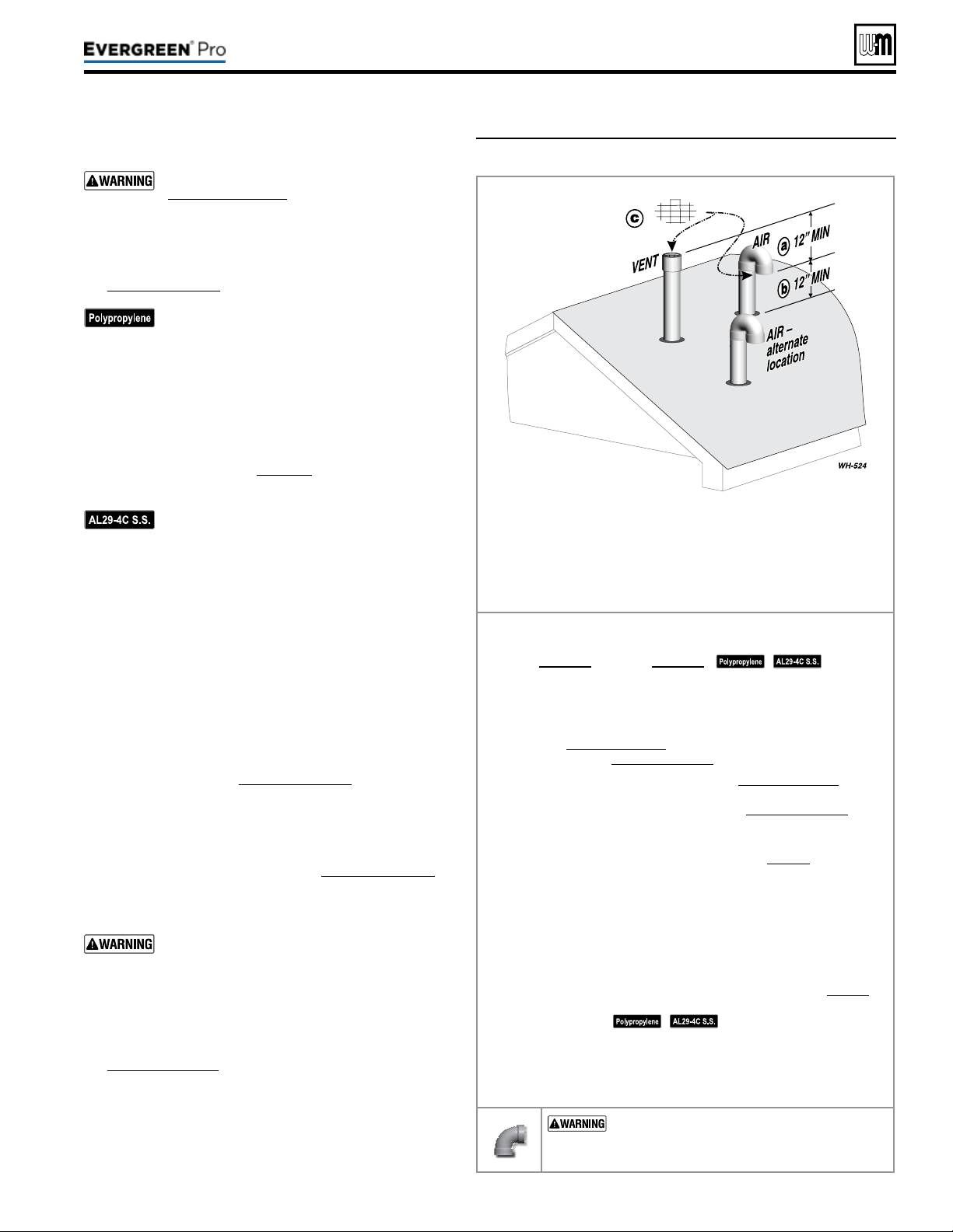
Figure37 Separate pipes vertical termination
Terminateventandairpipessuchthat:
a AIRINTAKEIS AT LEAST 12 inches below vent outlet.
b AIRINTAKEIS AT LEAST 12 inches above roof or snow line,
Keep vents/air intake area clear of accumulating snow.
c Ventandairterminationsarettedwithbirdscreens.
Step1 Read and follow all instructions in this manual. DO NOT
proceedwithvent/airinstallationuntilyouhaveread
page19throughpage24.
See notices
at le.
Step2 Install the boiler in a location that allows proper routing of all
vent and air piping to the selected location.
Step3 Make sure the selected vertical termination location complies
with Figure25,page23. (Multiple boiler terminations must also
comply with Figure38,page32.)
Step4 Use only the vent materials listed in Figure24,page21. Provide
pipe adapters where required. Vent piping and air piping lengths
must not exceed the values shown in Figure23,page20.
Step5 Prepare the vertical penetrations and secure penetration com-
ponents as instructed in this section. See “Prepare roof penetra-
tions” and “Termination and ttings” on page32.
Step6 e air piping must terminate in a 180-degree return bend or
down-turnedelbow as shown above. e vent piping must
terminate in a couplingpointedupward as shown above.
Step7 Install vent and air piping between the boiler and the vertical
terminations. Slope horizontal piping downward toward the
boiler at least 1/4 inch per foot. Install pipe supports every 5 feet
on both the horizontal and vertical runs. Install a hanger sup-
port within 6inches of any upturn in the piping. See page38 for
general guidelines. Also comply with vent pipe manufacturer’s
instructions.
See notices at le.
Step8 Insert the vent and air piping through the vertical penetrations
and secure the termination ttings.
Step9 Maintain clearances shown above. Vent and air terminations
must be tted with a bird screen as shown.
USESWEEPELBOWSFORALLVENTAND
AIRPIPING — DO NOT use short radius elbows
for vent or air piping. Boiler performance could be
aected.
Part number 550-100-211/0122
– 31 –
220 /29 9/3 00 /39 9
Loading ...
Loading ...
Loading ...