Loading ...
Loading ...
Loading ...
WARNING: Avoid eJectric shock, if the outlet you
are piannlng to use for this saw Is of the two prong
type, DO NOT REMOVE OR ALTER THE GROUND-
iNG PRONG IN ANY MANNER. Use an adapter, as
shown, and always connect the grounding lug to
a known ground, such as to a properly grounded
outlet box, Not aJll o_iet boxes are properly
grounded° If you are not sure the outlet box is
properly grounded, have It checked by a quaJified
electrlclan.
CHANGING MOTOR VOLTAGE
WARNING: Eiectric shock can kill.To avold
shock, never connect plug to power source outUet
until a_l assembly slops are completed. Unplug
saw before making or changing any connections.
1. Connections for 120v AC Operation
a. For operation on 120 volts, the bRackpower lead is
connected to spade terminal beside copper post.
The white power lead is connected to spade termi-
nal beside silver post. Thetwo movable links must
be in position shown in Figure 1, The red motor
lead is connected to terminal "B."
b. The movable links pivotonthe centermost screws.
After linkshave been correctly positioned, be sure
to tighten these screws to insure a good electricaI
connection.
120 VOLT CONNECTION
COPPER POST __-J_"4..\_
/r---- ....
BLACK POWER LEAD --n_ GREEN
GROUND SCREW
SPADE TERMINALS_. t _ .LINKS IN THIS
WHITE :OL_ER LEAD ?_ POSITION
B RED
_i ER POST
FIGURE 1
2. Connection for 240v AC Operation
a. For operation on 240 volts, the black power lead is
connected to spade terminal beside copper post.
The white power lead isconnected to spade termi-
nalbeside silver post. The two movable links must
be in position shown in Figure 2. The red motor
lead is connected to terminal "B."
b. The movable links pivot on the center most screv_,_ -
After links have been correctly positioned, be SL_r_
to tighten these screws to insure a good etectdc _
connection.
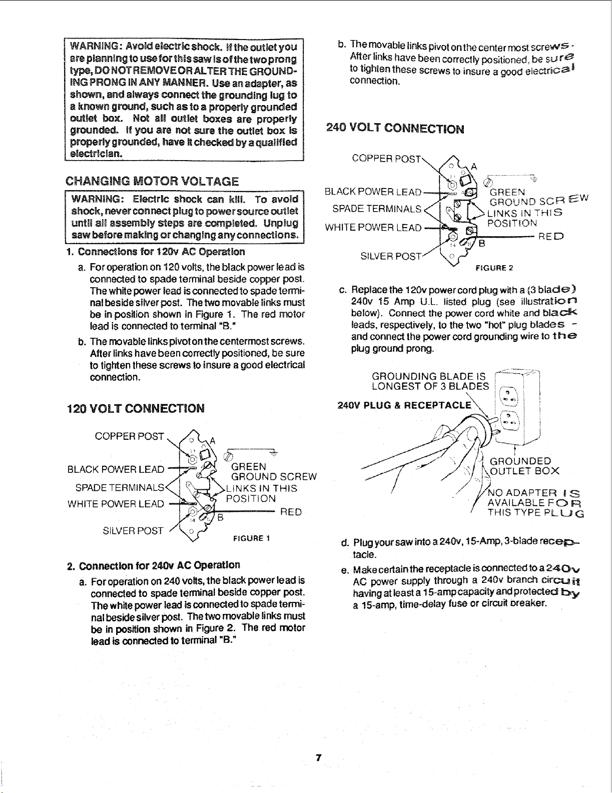
240 VOLT CONNECTION
COPPER
BLACK POWE
SPADE TERMINALS,
WHITE POWER
SILVER
GREEN
GROUND SCR E_.W
IN THIS
POSITION
RED
B
FIGURE 2
c. Replace the !20v power cord plug with a (3 blade)
240v 15 Amp U.L listed plug (see illustration
below). Connect the power cord white and black
leads, respectively, to the two "hot" plug blades -
and connect the power cord grounding wire to th_
plug ground prong.
GROUNDING BLADE tS -_..... J
LONGEST OF 3 BLADES ,--
24ov PLUG&RECEPTACLE i '--_ i
#
GROUNDED
OUTLET BOX
ADAPTEF{ I S
AVAILABLE FO F_
THIS TYPE PLUG
d. Plug yoursaw intoa 240v, 15-Amp, 3-blade receiz_-
tacle.
e, Make cerlain the receptacle isconnected to a 24(3Pv
AC power supply through a 240v branch circ:_ilt
having at least a 15-ampcapacity and protected by
a 15-amp, time-delay fuse or circuit breaker.
7
Loading ...
Loading ...
Loading ...