Loading ...
Loading ...
Loading ...
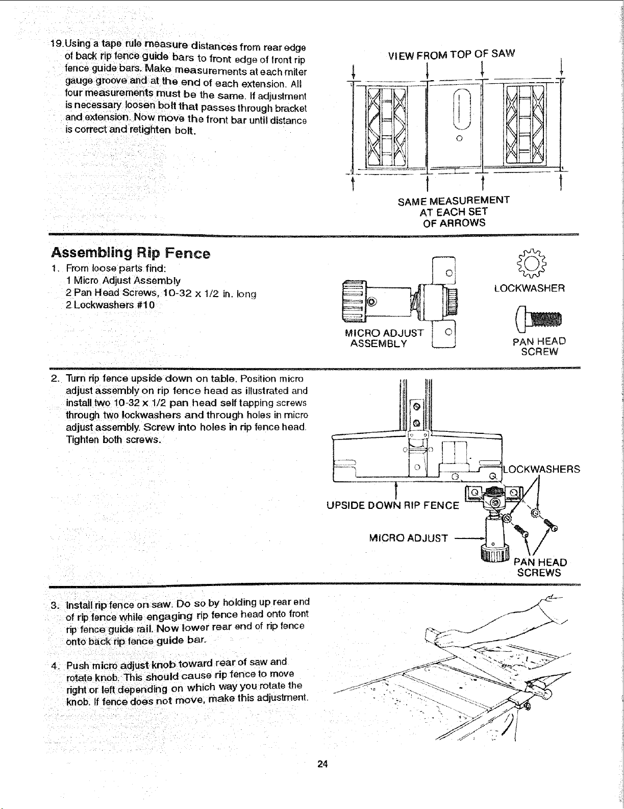
19. Using a tape rule measure distances from rear cage
of back rip fence guide bars to front edge of lront rip
fence guide bars. Make measurements at each miter
gauge grooveand at the end of each extension. A!I
tour measurements must be the same. If adiustment
is necessary loosen bolt that passes through bracket
and extension. Now move the front bar until distance
is correct and retighten bolt.
VIEW FROM TOP OF SAW
t
t
t,
t
SAME MEASUREMENT
AT EACH SET
OF ARROWS
Assembling Rip Fence
1. From loose parts find:
1 Micro Adjust Assembly
2 Pan Head Screws. 10-32 x 1/2 in. long
2 Lockwashers #10
MICRO ADJUST ; _!
ASSEMBLY
LOCKWASHER
PAN HEAD
SC REW
2.
Turn rip fence upside down on table. Position micro Jlq!llI:-
adjust assembly on rip fence head as illustrated and
install two 10-32 x 1/2 pan head self tapping screws ....,,
through two lockwashers and through holes in micro _]
adjust assembly. Screw into holes in rip fence head J
Tighten both screws. _,__S_ _ _
.... LOCKWASHERS"----__ i 1," ,
,,
UPSIDE DOWN RIP FENCE
PAN HEAD
SCREWS
3. Install rip fence on saw. Do so by ho_ing up rear end
of rip fence while engaging rip fence head onto front
rip fence guide rail. Now lower rear end of rip fence
onto back rip fence guide bar.
4. Push micro adjust knob toward rear of saw and
rotate knob. This should cause rip fence to move
dght or left depending on which way you rotate the
knob. tffence does not move, make this adjustment.
24
Loading ...
Loading ...
Loading ...