Loading ...
Loading ...
Loading ...
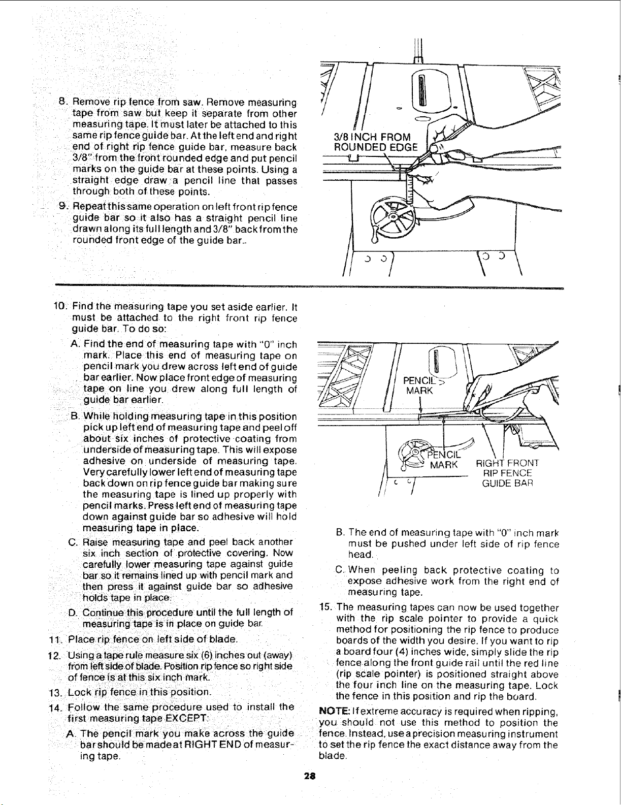
8. Remove rip fence from saw. Remove measuring
tapefrom saw but keep it separate from other
measuring tape. It must later be attached to this
same rip fence guide bar. At the left end and rig ht
end of right rip fence guide bar. measure back
3/8" from the front rounded edge and put pencil
marks on the guide bar at these points, Using a
straight edge draw a pencil line that passes
through both of these points.
9. Repeat this same operation on left front rip fence
guide bar so it also has a straight pencil line
drawn along its full length and 3/8" back from the
rounded front edge of the guide bar._
o
3/8 INCH FROM
ROUNDED EDGE
10. Find the measuring tape you set aside earlier. It
must be attached to the right front np fence
guide bar. To do so:
A. Find the end of measuring tape with "0" inch
mark. Place this end of measunng tape on
pencil mark you drew across left end of guide
bar earlier. Now place front edge of measunng
tape on line you drew along full length of
guide bar earlier,
B. While holding measuring tape in this position
pick up left end of measu ring tape and peel off
about six inches of protective coating from
underside of measuring tape. This wilt expose
adhesive on underside of measuring tape.
Very carefully lower left end of measuring tape
back down on rip fence guide bar making su re
the measunng tape is lined up properly with
pencil marks. Press left end of measuring tape
down against guide bar so adhesive will hold
measuring tape in place.
C, Raise measuring tape and peel back another
six inch section of protective covenng. Now
carefully lower measuring tape against guide
bar so it remainslined up with pencil mark and
then press it against guide bar so adhesive
holds tape in place.
D. Continue this procedure until the ful! length of
measuring tape is in place on guide bar.
11. Place rip fence on left side of blade.
12. Usingatape rule rneasure six (6) inches out (away)
from left s|deof blade. Position rip fence so righl side
of fence is at this six inch mark.
13. Lock rip fence in this position.
14. Follow the same procedure used to install the
first measuring tape EXCEPT:
A. The pencil mark you make across the guide
bar shou}d be made at RIGHT END of measur-
ing tape
/_ _- MARK RIGHT FRONT
t| _cl RIP FENCE
/ c / GUIDE BAR
B. The end of measunng tape with "0" .,ncn mark
must be pushed under left side of rip fence
head
C. When peeling back protective coating to
expose adhesive work from Lhe right end of
measu ring tape,
15. The measuring tapes can now be usec together
with the rip scale pointer to provide a quick
method for positioning the rip fence to produce
boards of the width you desire, If you want to np
a board four (4} inches wide. simply slide the rip
fence along the front guide rait until the red line
(rip scale pointer) is positioned straight above
the four inch line on the measuring tape. Lock
the fence in this position and rip the board.
NOTE: If extreme accuracy is required when ripping,
you should not use this method to position the
fence. Instead. use a precision measuring instrument
to set the rip fence the exact distance away from the
blade.
28
Loading ...
Loading ...
Loading ...