Loading ...
Loading ...
Loading ...
Operation
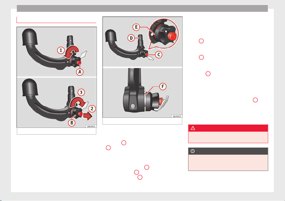
Placing in service position
Fig. 195 Placing in service position.
Fig. 196 Service position.
Before assembling, place the ball-headed bar
in ser
v
ic
e position.
–
Turn key
A
fully in the direction of arrow
1
›
›
› Fig. 195
.
–
Hold the ball-headed bar with your left
hand.
–
Pull manual regulator
B
outward in the di-
r
ection of
arr
ow
2
and turn it fully in the
dir
ection of
arr
ow
3
.
The manual regulator will remain in this posi-
tion.
Ser
v
ic
e position ››› Fig. 196
●
Key
C
is in an open position – the key ar-
r
o
w points
to the “unlocked” symbol. The key
cannot be removed from the key slot.
●
The
D
locking balls may be fully inserted
int
o the body
of
the ball-headed bar by ap-
plying some pressure.
●
The red
E
marking on the manual regula-
t
or points
t
owards the white marking on the
ball-headed bar.
●
Between the manual regulator and the
body of the ball-headed bar there is a clearly
visible space of approximately 4 mm
F
.
Onc
e the b
al
l-headed bar has been posi-
tioned like this, it will be ready to be placed
in the clamping bush.
WARNING
Do not use the ball-headed bar if it cannot be
correctly
placed in the service position.
CAUTION
The key cannot be removed from the manual
regu
lator key slot when it is in the service po-
sition.
190
Loading ...
Loading ...
Loading ...