Loading ...
Loading ...
Loading ...
14
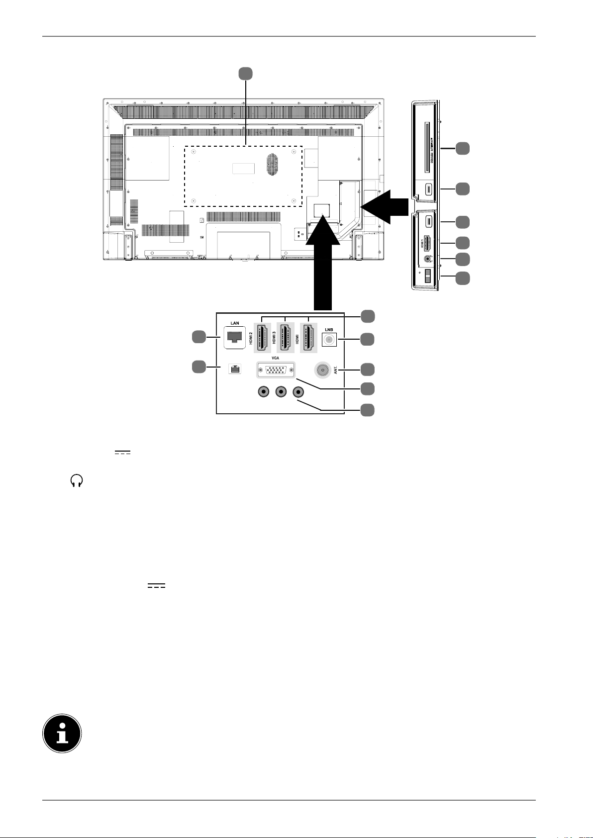
5.2. Rear and right-hand side
13
(ARC)
6
8
9
11
12
SPDIF
Optic. out
10
L
R
Video
BACK AV IN
13 Vdc/18 Vdc
300mA Max.
7
4
MODE - / I
- O +
USB
5Vdc
Max. 500mA
USB
5Vdc
Max. 500mA
1
2
2
3
4
5
1) COMMON INTERFACE (CI+): Card slot for connecting pay TV cards
2) USB (5V
, 500 mA max.): USB connection for media playback/recording (PVR)
3) HDMI 1: HDMI connection for devices with a HDMI output
4)
: For connecting headphones with 3.5 mm jack
5) MODE: Multifunction button for channel switching, input source selection or volume adjust-
ment. Settings are made by tilting upwards (+) or downwards (-). Pressing the button briefly
switches between functions. A long press switches the device into standby mode or operat-
ing mode.
6) HDMI 2-4: HDMI connection for devices with a HDMI output (HDMI 2 can be used for CEC/
ARC)
7) LNB (13 V/18 V
, 300 mA max.): For connecting the antenna (satellite)
8) ANT.: For connecting an aerial (analogue, DVB-T or DVB-C)
9) VGA: VGA port for connecting a PC or a YUV adapter (optional)
10) BACK AV IN: Audio/video input (cinch)
11) SPDIF Optic. OUT: Digital audio output (optical)
12) LAN: Network connection to connect to the Internet
13) Fixing holes for a wall mount
1
MD 32210: Vesa standard, hole spacing 200 x 200 mm
MD 32211, MD 32212: Vesa standard, hole spacing 400 x 200 mm
The wall mounting of the TV device must not exceed a height of 2 m. The device need to
be mounted on rigid surfaces such as cement or concrete.
1
Wall mount not supplied. When mounting the device, make sure that you use M6 screws. The length of the screws corresponds to the thickness
of the wall bracket plus 10 mm.
Loading ...
Loading ...
Loading ...