355-0786
PAGE: 1 / 9
231129
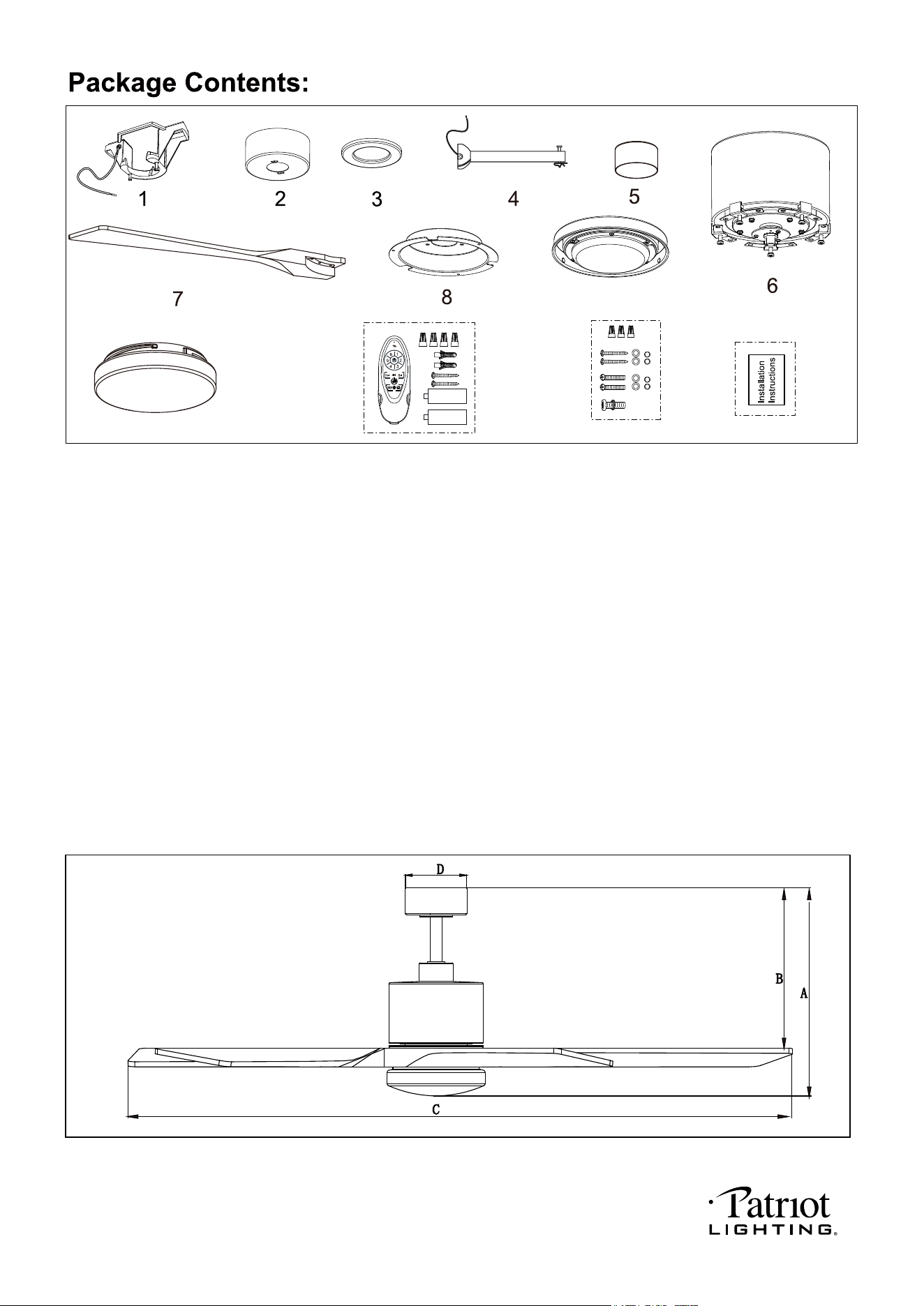
A. 16-3/4" B. 12-3/4" C. 60" D. 5"
Unpack your fan and check the contents. You should have the following items.
11
10
9
X 16
1312
Dimension Reference (Installed with 6" Downrod)
1.) Hanger Bracket
2.) Canopy
3.) Decorative Cap (Comes in a Separate Bag)
4.) Downrod Set (Included Hanger Ball, 6" Downrod, Hanger Pin & Lock Pin)
5.) Downrod Stand Cover
6.) Fan Motor Assembly
7.) Fan Blades (5PCS)
8.) Connect Plate of Light Kit
9.) Light Kit with LED Module
10.) Glass Shade
11.) Remote Control Set (Included Transmitter & Wire Connectors & Batteries & Screws )
12.) Assembly Kit
13.) Installation Instructions
CCT
1.5V
1.5V
PAGE: 2 / 9
231129
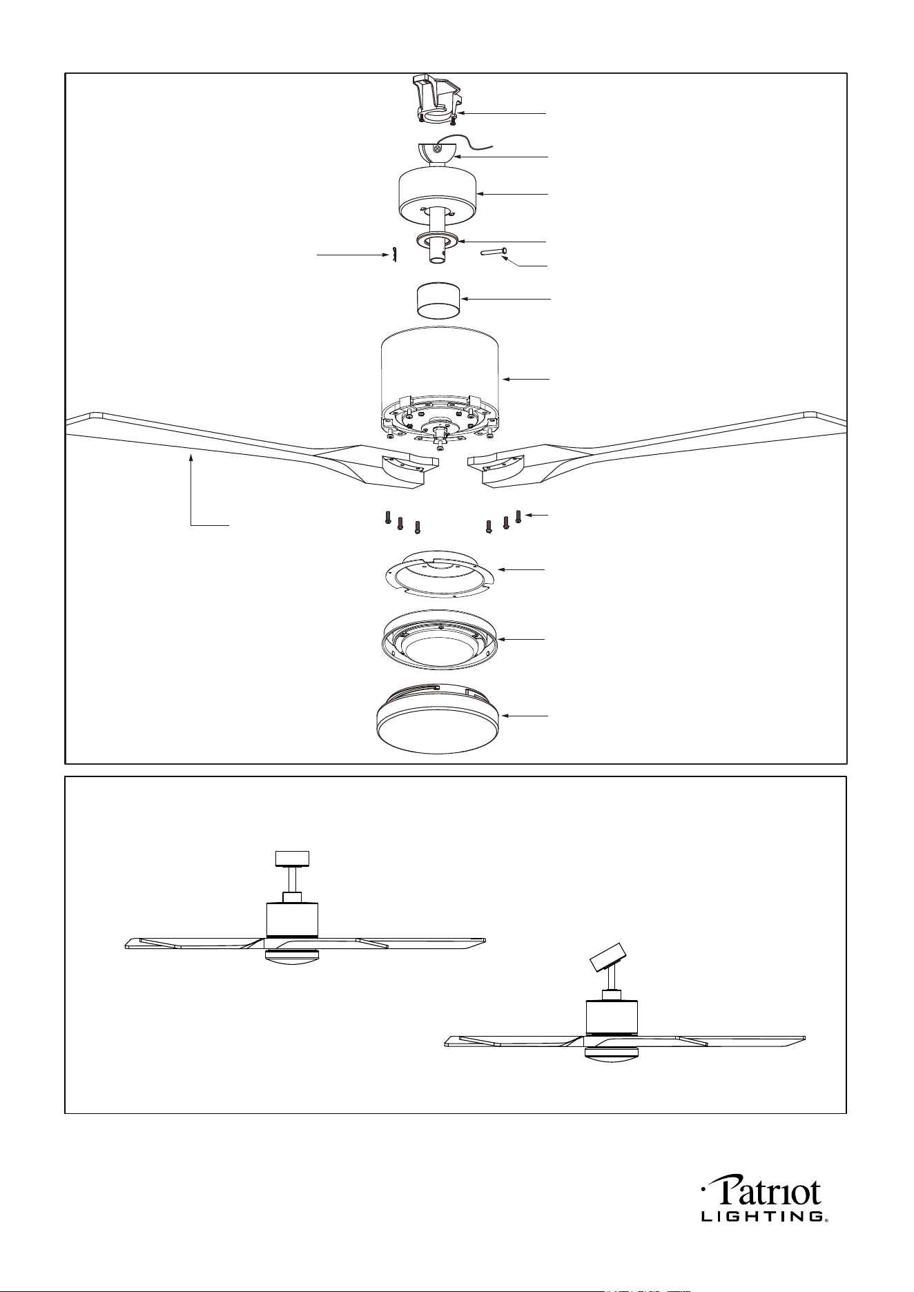
Dual Mount Drawing
Downrod Mount
Sloped Ceiling Mount (Up to 23 degrees)
Exploded View Detail
Hanger Bracket
Hanger Ball
Canopy
Decorative Cap
Fan Motor Assembly
Hanger Pin
Lock Pin
Fan Blade
Glass Shade
Light Kit with LED Module
Connect Plate of Light Kit
Motor Screws
Downrod Stand Cover
PAGE: 3 / 9
231129
WET
PAGE: 4 / 9
THE FAN CAN WITHSTAND DIRECT RAIN,
SNOW OR EXCESSIVE MOISTURE AS IN AN OPEN GAZEBO.
231129
Note: For sloped ceiling installation, make
sure that the chip of the hanger bracket
is toward the floor.
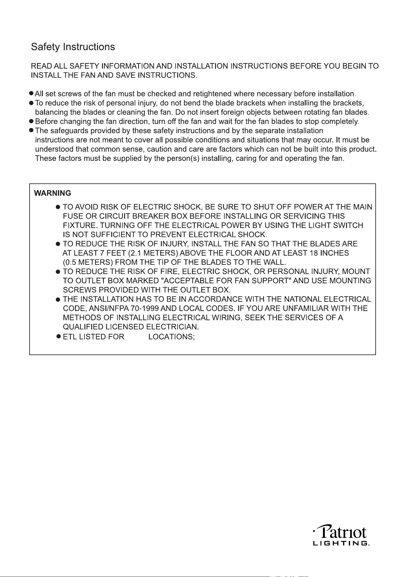
IMPORTANT:
BEFORE YOU BEGIN INSTALLATION, CAREFULLY READ ALL INFORMATION PROVIDED IN THE SAFETY
INSTRUCTIONS AND INSTALLATION INSTRUCTIONS. IF IN DOUBT, CONSULT A QUALIFIED
ELECTRICIAN.
SAVE ALL INSTRUCTIONS.
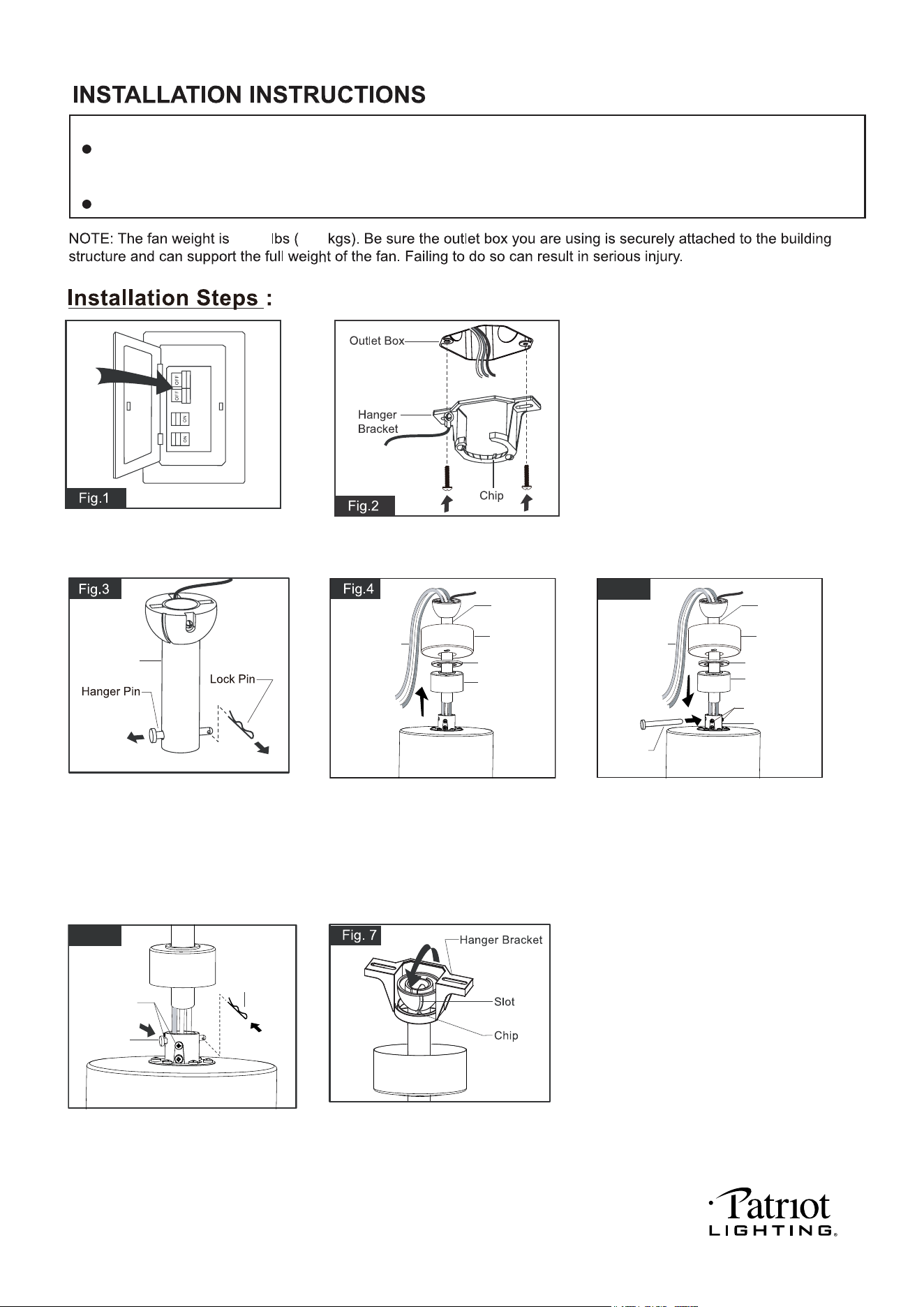
Tighten the two collar screws.
Slide lock pin into hanger pin until
it is locked into position.
Remove the lock pin from hanger
pin and remove the hanger pin
from the downrod.
Turn OFF the electric circuit at the
main fuse or circuit breaker box.
Hang the fan on hanger bracket, and
make sure the slot of hanger ball is
snapped into the chip of hanger bracket
exactly.
Note: For sloped ceiling installation,
make sure the slot of hanger ball and
the chip of hanger bracket face down.
Tighten the hanger bracket to the outlet box
with two mounting screws. (To reduce the
risk of fire, electric shock, or personal injury,
mount to an outlet box marked "Acceptable
for fan support" and use mounting screws
provided with the outlet box.)
Downrod
Canopy
Motor Wires
Decorative Cap
Downrod Stand
Cover
Downrod
Fig.6
Lock Pin
Collar Screw
Hanger Pin
Canopy
Motor Wires
Collar Screw
Collar
Decorative Cap
Downrod Stand
Cover
Downrod
Fig.5
Hang Pin
Slide canopy, decorative cap
(Making sure the smooth side
of decorative cap is facing
downward.), downrod stand
cover onto downrod, as shown;
then thread motor wires through
downrod.
Loosen the collar screws out part way.
Insert the downrod into the collar.
Slide hanger pin through holes of collar
and downrod.
PAGE: 5 / 9
15.28
6.93
231129
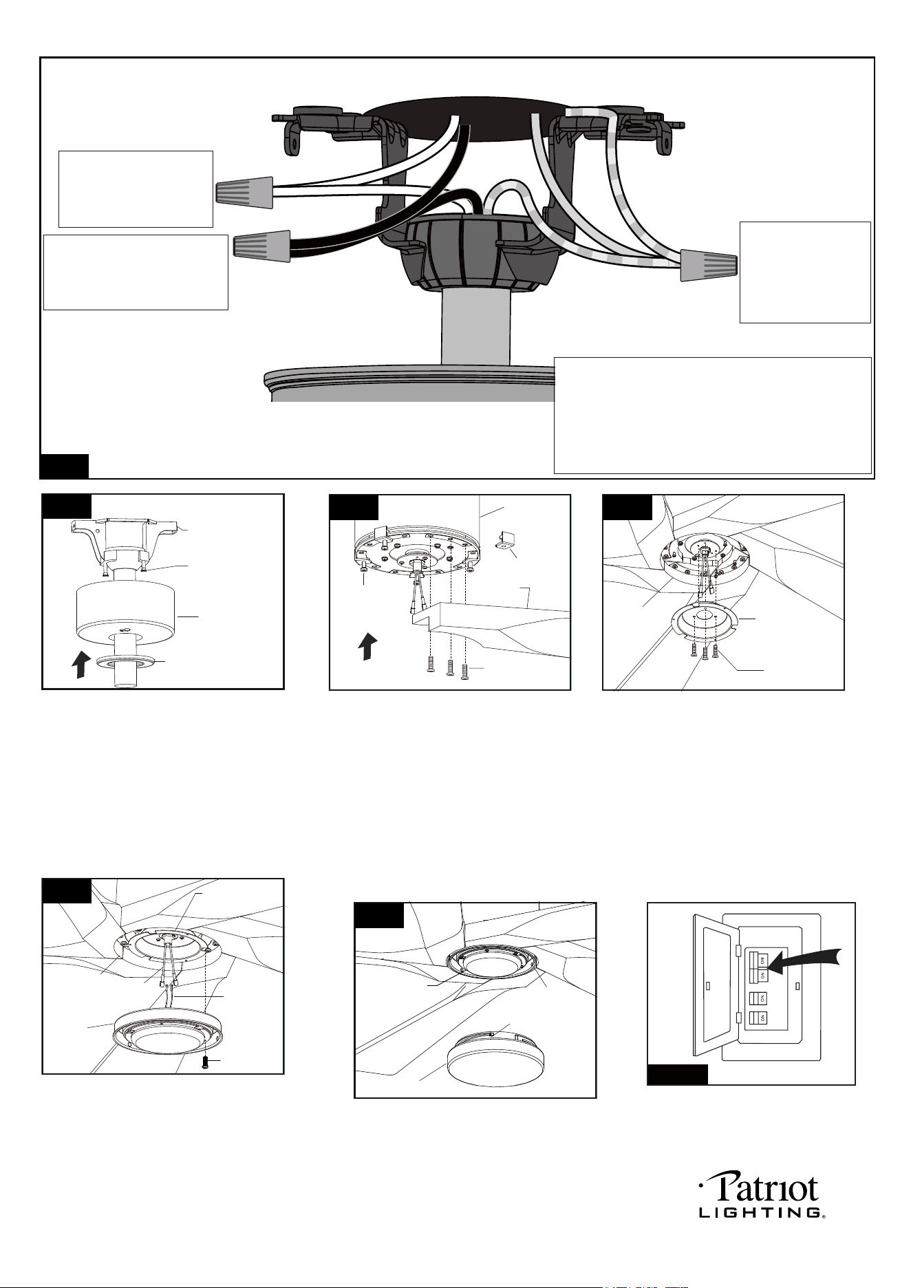
Fig.14
Turn ON the electric cicuit at the main
fuse or circuit breaker box.
Slide the canopy up to ceiling and over the
two canopy screws on hanger bracket. Rotate
canopy clockwise, next, while holding the canopy
with one hand, slide the decorative cap over the
screws and rotate clockwise until tight.
Note: Adjust the canopy screws as necessary
until the canopy and decorative cap are snug.
Canopy Screw
Hanger Bracket
Canopy
Decorative Cap
Fig.9
Fig.8
Connect the white (neutral)
wire from motor to the white
(neutral) wire from the
outlet box with a wire
connector.
Connect the black (hot) wire
(This is for fan and light control)
from motor to the black (hot) wire
from outlet box with a wire
connector.
Bla
Black
ck
Green
White
White
Grounding
Green
*** After making the wire connections, the wires should
be spread apart. The white (neutral) conductor and
green (grounding) conductor on one side and the
black (hot) conductor on the other side of the outlet
box.
*** The wire connection points should be turned upward
and pushed carefully up into outlet box.
Connect three
ground wires (Green
or bare copper) coming
from outlet box,
downrod and hanging
bracket with a wire
connector.
Fig.10
Fan Motor
Assembly
Blade
Blade Screw
Plastic Insert
Plastic Insert
Screw
Remove the plastic insert screws and
plastic inserts from the fan motor assembly
first. Align the holes on one of the blades
with the holes on the bottom of fan motor
assembly, then loosely attach the blade
using the screws provided using the
screws provided in the bag of assembly kit.
Repeat this process for other blades. Once
five blades are in position and connected
with blade screws firmly tighten all screws.
Note: Before installing blades to the fan
motor assembly, please remove the plastic
insert screws and plastic inserts.
PAGE: 6 / 10
Fig.11
Connect Plate
of Light Kit
Set Screw
Fan Motor
Assembly
Remove one screw (for later use) and loosen
another two screws from connect plate of light
kit first. Then connect the white (neutral) wire
from the light kit with LED module to white
(neutral) wire from fan motor assembly; connect
the blue (hot) wire from the light kit with LED
module to blue (hot) wire from fan motor assembly.
Finally, carefully put the wires into the connect plate
of light kit, then attach the light kit with LED module
onto the connect plate of light kit with previous screws.
Attach the glass shade to the light kit with
LED module by aligning studs and slots,
and turn it clockwise until it is locked in place.
Fig.13
Light Kit with
LED Module
Stud
Glass Shade
Slot
PAGE: 6 / 9
Remove three set screws from fan motor
assembly first (for later use), then thread
the fan motor assembly wires through
connect plate of light kit. Push the connect
plate of light kit upwards then align and
engage the connect plate of light kit holes
to fan motor assembly holes. Finally, secure
the connect plate of light kit to the fan motor
assembly bottom with previous screws which
were removed.
Set Screw
Light Kit with
LED Module
Connect Plate
of Light Kit
Fig.12
Fan Motor
Assembly
Female
Terminal
Male
Terminal
231129
Transmitter
Wall Bracket
Anchor
Screw
Fig.16
CCT
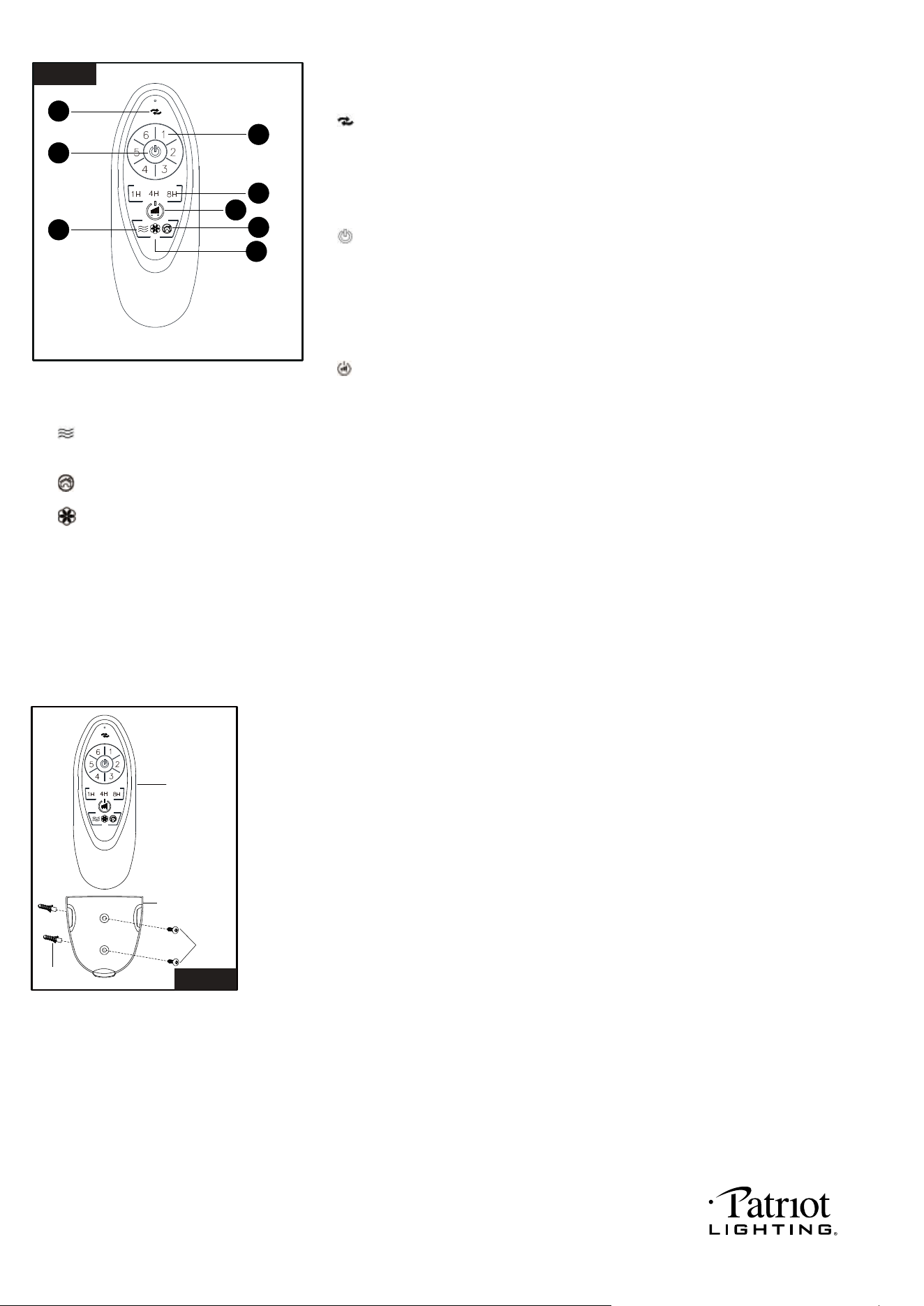
Install the transmitter wall bracket on the wall with two anchors and two screws
and place transmitter in it carefully .
1
3
6
2
4
5
7
8
Fig.15
Remote Control Transmitter
CCT
Remote controller
Install two 1.5 volt batteries (type AAA, included) into the remote controller.
The remote buttons instruct as below:
1. " " Reverse button:
Press this button to control fan direction.
The lateness of reverse function is normal, please wait for a moment.
2. Fan speed:
1 = minimum speed 2 = low speed
3 = medium low speed 4 = medium speed
5 = medium high speed 6 = high speed
3. " " Button:
Press this button to turn the fan off.
4. Timer Control:
Press "1H","4H" or "8H" button to stop the fan speed and light after that period.
Press fan off button to stop the fan speed timer control, and fan also will be turn off.
Press quickly light on/off button to stop the lighting timer control, and light also
will be turn off.
Turn OFF the electric circuit at the main fuse or circuit breaker box to stop timer control.
5. " " light on/off and dimmer button:
Press this button quickly to turn on or turn off the light. Press and hold this button to
dim or brighten lights to the desired level then release, and the brightness level will be
memorized.
6. " " Breese button:
Press breese button to control the fan speeds automatic cycle between 1 to 6 speeds with a 20-second frequency. And any other fan
speed button can be stop this function.
7. " " Vacation mode button: Press vacation mode button to turn on the light 5 minutes each 2 hours, any other button can be stop
this function.
8. " " button:
Press this button to change color temperature of fan light, there are a total of 5 levels of color changing from 2700K,3000K,3500K,
4000K to 5000K.
Note:
1. This remote controller has a memory function setting. The fan will operate at the same speed and the fan light will stay at the
same brightness-level as the last time the power supply was turned off.
2. Included transmitter matched with receiver in the motor.
3. One transmitter can be compatible with 4pcs ceiling fan and every ceiling fan can be compatible with new transmitter
according press and hold the fan off button with 5 seconds until you hear the indicator sound of swoosh from the transmitter
and this step should be done within 30 seconds time frame after the main power is turned on.
PAGE: 7 / 9
231129
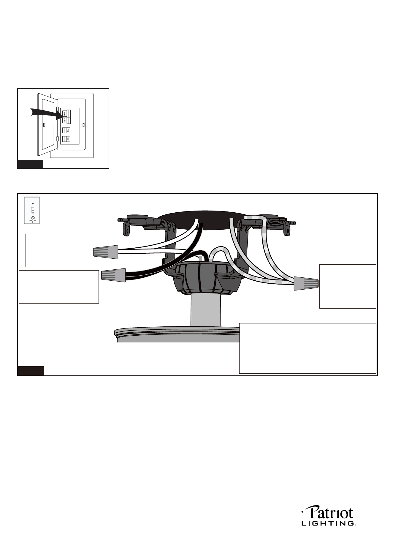
Fig.18
Connect the white (neutral)
wire from motor to the white
(neutral) wire from the
outlet box with a wire
connector.
Bla
Black
ck
Green
White
White
Grounding
Green
*** After making the wire connections, the wires should
be spread apart. The white (neutral) conductor and
green (grounding) conductor on one side and the
black (hot) conductor and blue (light) conductor on
the other side of the outlet box.
*** The wire connection points should be turned upward
and pushed carefully up into outlet box.
Connect three
ground wires (Green
or bare copper) coming
from outlet box,
downrod and hanging
bracket with a wire
connector.
For a single switch
Follow these steps:
PAGE: 8 / 9
Note:1. Compatible with on/off function wall switch only.
2. The direction of fan rotation can not be set without remote controller.
3. The color temperature and brightness of light can not be set without remote controller.
Turn OFF the electric circuit at the main fuse or circuit breaker box. (See Fig.17)
Install Without Remote Controller
Fig.17
Connect the black (hot) wire
(This is for fan and light control)
from motor to the black (hot) wire
from outlet box with a wire
connector.
231129

231129
PAGE: 9 / 9
Troubleshooting Guide
If you have difficulty operating your new ceiling fan, it may be the result of incorrect assembly, installation
or wiring. In some cases, these installation errors may be mistaken for defects. If you experience any
faults, please check this Troubleshooting Guide. If a problem cannot be remedied or you are
experiencing difficulty in installation, please call our Customer Service Department (1-800-887-6326).
PROBLEM
1. If fan does not start:
2. If fan sounds noisy:
3. If fan wobbles:
4. If light does not work:
5. If fan and light kit do
not work:
1. Check main and branch circuit fuses or circuit breakers.
2. Check line wire connections to fan and switch wire connections in switch
housing.
CAUTION: Make sure main power is turned off.
3. Make sure that the wall control is turned "ON".
1. Make sure all screws in motor housing are snug. (not too tight)
2. Make sure the screws which attach the fan blade bracket to the motor are tight.
3. Make sure wire connectors in switch housing are not rattling against each
other or against the interior wall of the switch housing.
CAUTION: Make sure main power is turned off before accessing switch
housing.
4. Some fan motors are sensitive to signals from Solid State variable speed
controls. DO NOT USE a Solid State variable speed control.
5. Allow "break-in" period of 24 hours. Most noises associated with a new fan will
disappear after this period.
All blades are weighed and grouped by weight. Natural woods vary in density
which could cause the fan to wobble even though all blades are weight-matched.
The following procedures should eliminate most of the wobble. Check for wobble
after each step.
1. Check that all blades are screwed firmly into blade brackets.
2. Check that all blade brackets are tightened securely to motor.
3. Make sure that canopy and mounting bracket are tightened securely to ceiling
junction box and junction box is mounted firmly to ceiling joist.
4. Most fan wobble problems are caused when blades are not equally level. To
check the blade levels, select a point on the ceiling above the tip of any blade.
Measure the distance from the ceiling to the blade tip, to an accuracy of 1/8
inch. Rotate the blades until the next blade is in the measuring position. Repeat
measurement for each blade. If all blade levels are not equal, you can adjust
blade levels by the following procedure. To adjust a blade tip down, insert a
washer (not supplied) between the blade and blade bracket at the screw
closest to the motor. To adjust a blade tip up, insert washer (not supplied)
between the blade and blade bracket at the two screws farthest from the motor.
5. If blade wobble is still noticeable, interchanging two adjacent (side by side)
blades can redistribute the weight and possibly result in smoother operation.
1. Check blue wire from fan to make sure it is connected to hot wire from house.
2. Check for loose or disconnected wires in fan switch housing.
3. Check for loose or disconnected wires in light kit.
4. Check for faulty the LED module.
CAUTION: Make sure main power is turned off before accessing switch
housing.
SUGGESTED REMEDY
1. Replace the battery of transmitter.
2. Re-pair the transmitter and receiver by holding the "FAN OFF" button on the
transmitter according to the manual.
