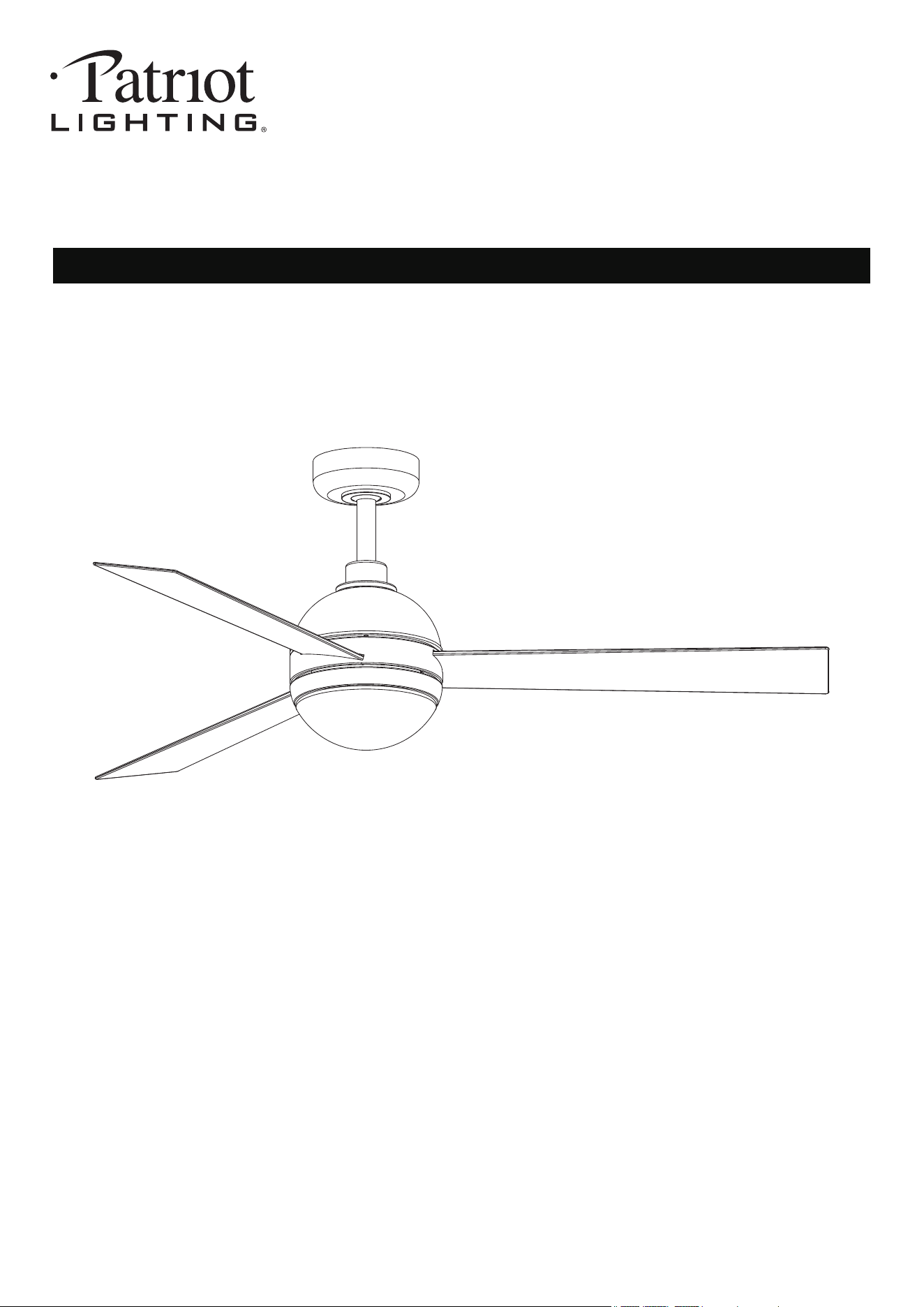
52" Downrod Mount
Ceiling Fan
SKU Number:355-3400
Model Number:47585-MNDBB
Questions, problems, missing parts? Before returning to your retailer, call our customer service
250215
department at 1-833-695-2045, 8:30 a.m. - 5 p.m., EST, Monday - Friday.
250215
the product.
To reduce the risk of injury to person, make sure a location selected for the fan allows clear space
for blades to rotate, and at least seven(7) feet(2.1 Meters) of clearance between the floor and the
fan blade tips.
WARNING- To Reduce The Risk Of Fire Or Electric Shock, Do Not Use This Fan With Any Solid-State
Speed Control Device.
WARNING- TO REDUCE THE RISK OF FIRE, ELECTRIC SHOCK, OR INJURY TO PERSONS,
OBSERVE THE FOLLOWING:
Please read and understand this entire manual before attempting to assemble, operate or install
1.
and local electrical code. If you are unfamiliar with wiring or are in doubt, consult a qualified
electrician.
All electrical connections must be in accordance with the National Electrical Code ANSI/NFPA70
2.
To reduce the risk of electric shock, turn the electricity off at main fuse box or circuit breaker
before beginning fan installation or servicing the fan. Do not operate fan without blades.
3.
4.
To reduce the risk of personal injury, use only approved mounting bracket, those parts and screws
supplied with the fan or accessories designated specifically for use with the fan.
5.
After completing installation, check all set screws and make sure they are firmly secured.
6.
with the light kits and switches for proper assembly and installations.
Choose fan and light switches must be UL or ETL general use. Refer to the instructions packaged
7.
Do not operate reversing switch while fan blades are in motion. Fan must be turned off and blades
stopped before reversing blade direction.
8.
Do not use water or detergents when cleaning the fan or fan blades. A dry cloth or lightly damped
cloth will be suitable for most cleaning.
9.
a) Use this unit only in the manner intended by the manufacturer. If you have question, contact
the manufacturer.
b) Before servicing or cleaning unit, switch power off at service panel and lock the service
disconnecting means to prevent power from being switched on accidentally. When the service
disconnecting means cannot be locked, securely fasten a prominent warning device, such as a
tag, to the service panel.
CAUTION- To avoid personal injury, the use of gloves may be necessary while handling fan parts
with sharp edges.
WARNING- To reduce the risk of fire, electric shock or personal injury, mount the fan to outlet box
marked ACCEPTABLE FOR SUPPORT of at least 15.9 kgs(35 lbs), and use mounting screws
provided with the outlet box. Most outlet boxes commonly used for the support of luminaries and not
acceptable for fan support and may need to be replaced. Consult a qualified electrician if in doubt.
WARNING- Using parts and or accessories other than those supplied with the fan could result in
injury or property damage and will void the warranty.
WARNING- To reduce the risk of personal injury, do not insert foreign objects in between rotating
fan blades.
WARNING- To reduce the risk of electric shock, disconnect the electricity supply circuit to the fan
before installing light kit.
CAUTION - To Reduce The Risk Of Electric Shock, Disconnect The Electrical Supply Circuit To
The Fan Before Installing Light Kit.
WARNING - If unusual oscillating movement is observed, immediately stop using the ceiling fan
and contact the manufacturer, its service agent or suitably qualified persons.
WARNING- To Reduce The Risk Of Fire.Electric Shock Or Injury To Persons, Do Not Use
Replacement Parts That Have Not Been Recommended By The Manufacturer (e.g. Parts Made At
Home Using A 3D Printer).
2 15
-Reorient or relocate the receiving antenna.
-Increase the separation between the equipment and receiver.
-Connect the equipment into an outlet on a circuit different from that to which the receiver is connected.
-Consult the dealer or an experienced radio/TV technician for help.
NOTE 2-Any changes or modifications to this unit not expressly approved by the party responsible for
compliance could void the user's authority to operate the equipment.
Company Name: Eurofase Inc.
Company Address: 60 Industrial Parkway, Unit 802, Cheektowaga, NY 14227-2713
Telephone Number: 1-833-695-2045 Fax: 905-695-2056
NOTE 1- This equipment has been tested and found to comply with the limits for a Class B digital device,
pursuant to part 15 of the FCC Rules. These limits are designed to provide reasonable protection against
harmful interference in a residential installation. This equipment generates, uses and can radiate radio
frequency energy and, if not installed and used in accordance with the instructions, may cause harmful
interference to radio communications. However there is no guarantee that interference will not occur in a
particular installation. If this equipment does cause harmful interference to radio or television reception,
which can be determined by turning the equipment off and on, the user is encouraged to try to correct the
interference by one or more of the following measures:
This device complies with part 15 of the FCC Rules. Operation is subject to the following two conditions:
(1) This device may not cause harmful interference, and (2) this device must accept
any interference received, including interference that may cause undesired operation.
250215
3 15
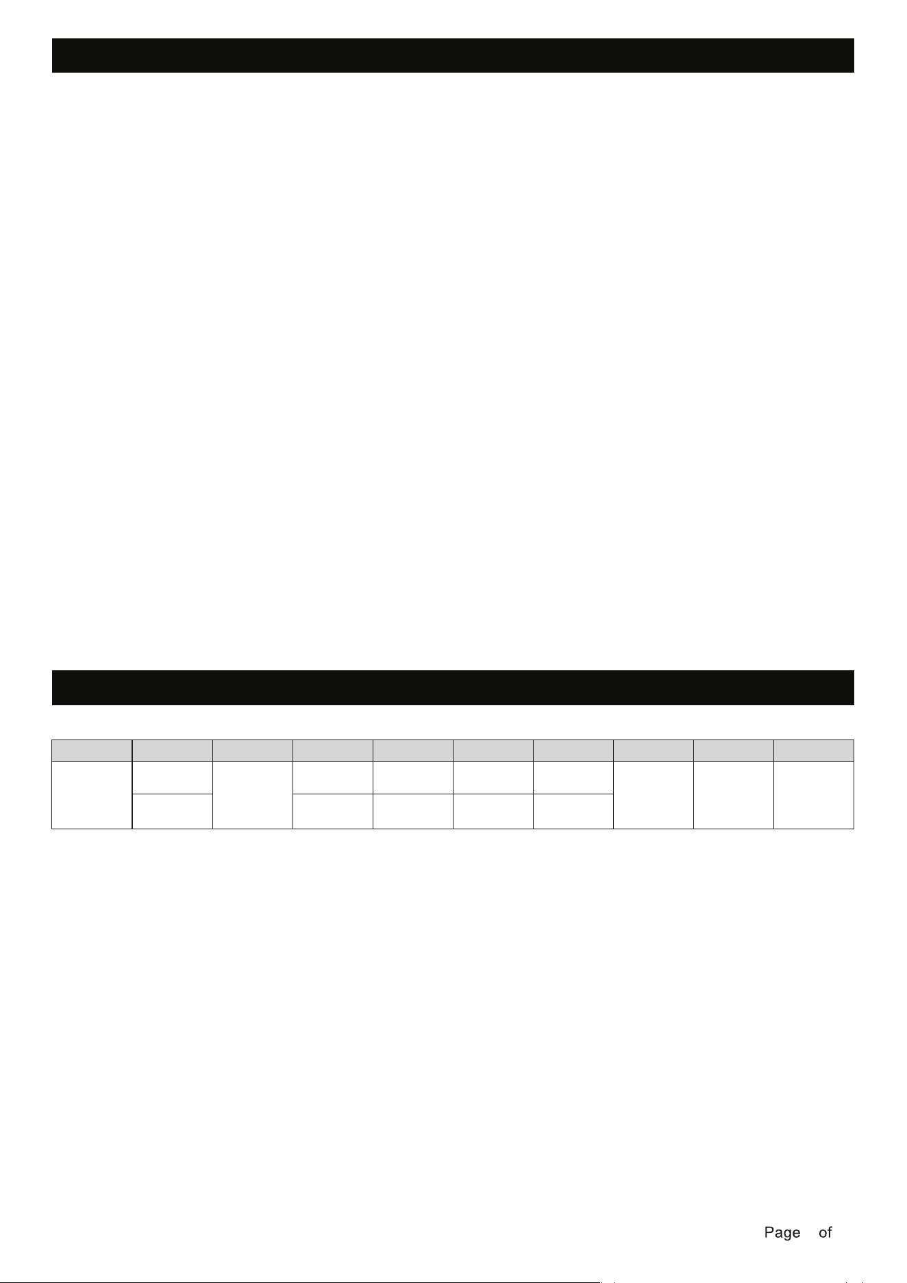
SPECIFICATIONS
FCC STATEMENT
Fan size Speed
HIGH
LOW
Volts Amps Watts RPM CFM Net Wt Gross Wt Cubic Ft
52in.
120
0.47
0.05
32.09
2.58
194
72
1.85’
12.35lbs
(5.6kg)
17.64lbs
(8kg)
4174.3
1561.01
TOOLS REQUIRED
250215
4 15
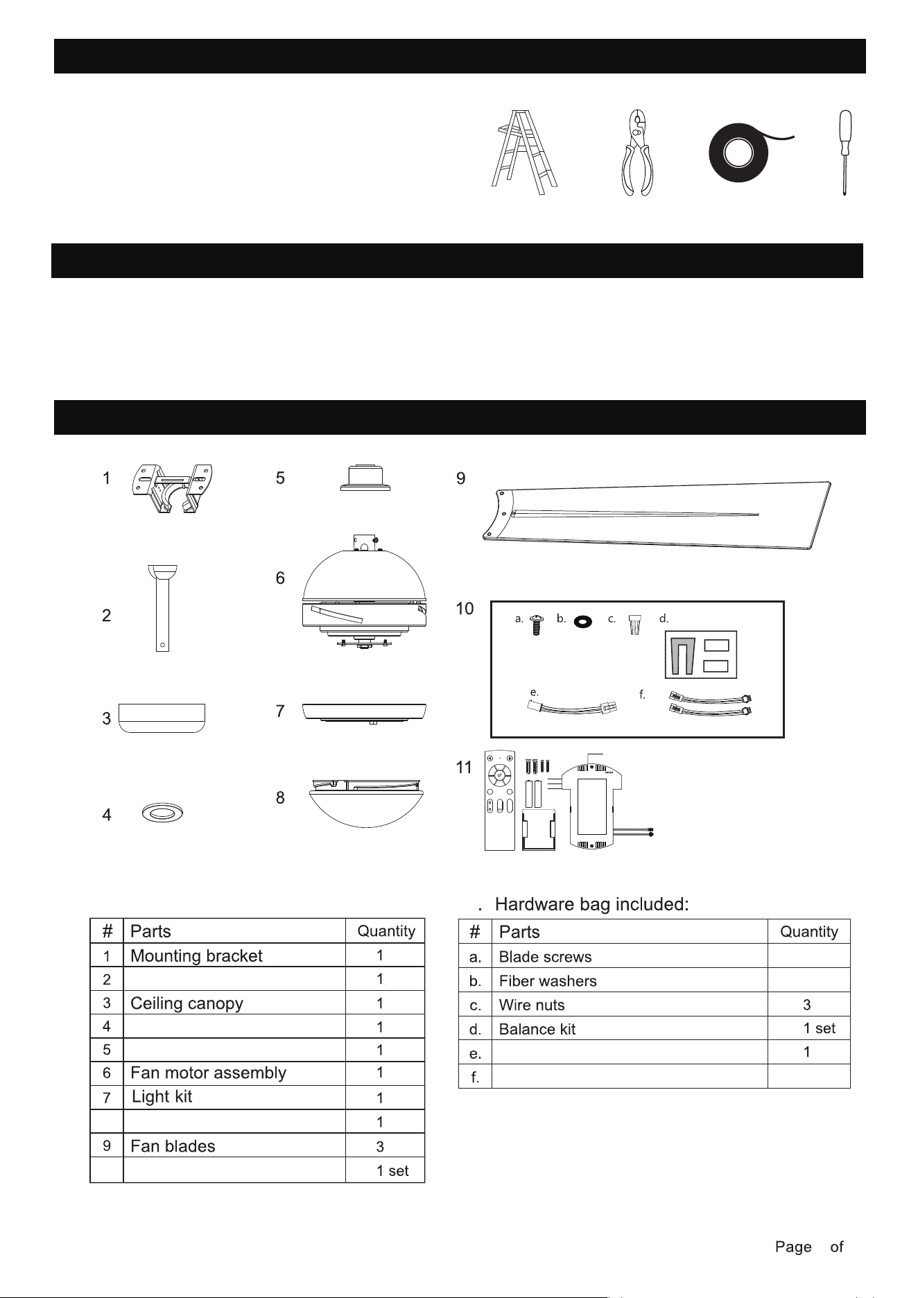
UNPACKING FAN
PACKAGE CONTENTS
Ladder
Wire Strippers
Electrical Tape
Carefully open the packaging. Remove items from pulp tray inserts. Remove motor housing
and place on clean floor or pulp tray to avoid damage to finish.
Do not discard fan carton or pulp tray inserts should this fan will need to be returned for repairs.
Check against parts list that all parts have been included.
Phillips Screwdriver
Canopy cover
Coupling cover
Remote control
Lamp shade
Hanging ball assembly
8
10
2
10
11
10.
Extension wire for motor
Extension wire for lights
1
2
3
4
5
6
LED
-
Demo
LED
+
CCT
250215
5 15
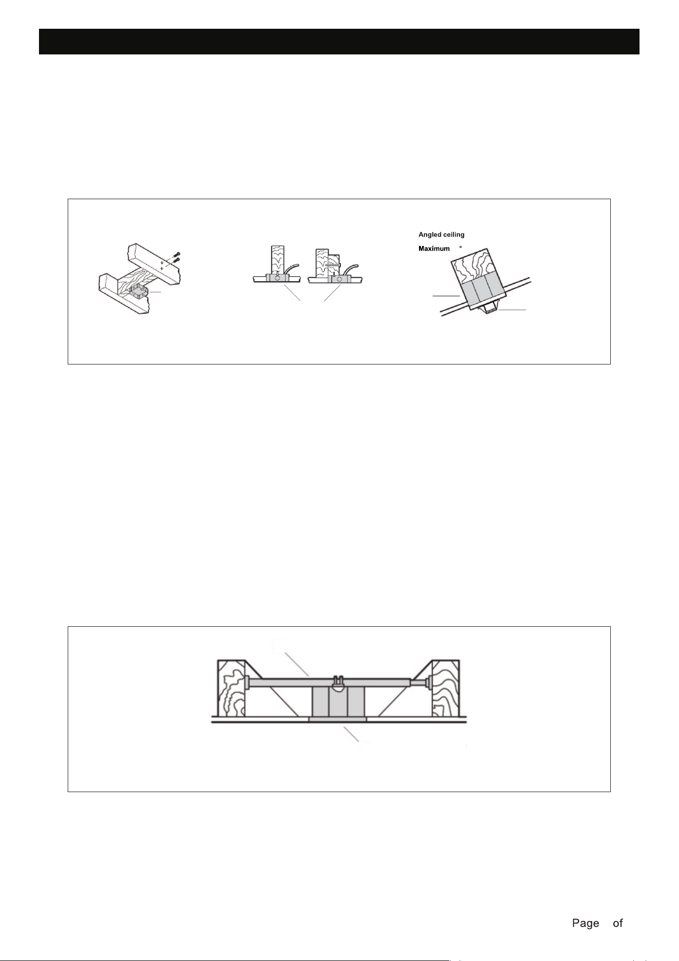
MOUNTING OPTIONS
If there isn't an existing outlet box, then install one using the following instructions:
This fan hanging system supports a maximum 18 degree angled ceiling installation. Option 3.
To hang your fan where there is an existing fixture but no ceiling joist, you may need an installation
hanger bar as shown below. Make sure the hanger bar you purchase has been designed for use
with ceiling fans.
NOTE: lf you are installing the ceiling fan on a sloped ceiling, you may need a longer downrod to
maintain proper clearance between the tip of the blade and the ceiling.
NOTE: The ceiling fan must be installed in a location so that the blades are spaced 300 mm from
the tip of the blade to the nearest objects or walls.
NOTE: For angled ceiling installation, the opening of the mounting bracket must be pointed to
ward the peak.
fasteners and materials (not included). The outlet box and its bracing must be able to fully
support the weight of the moving fan (at least 35 lbs). Do not use a plastic outlet box.
• Disconnect the power by removing the fuses or turning off the circuit breakers.
• Figures below show three different ways to mount the outlet box (not included).
• Secure the outlet box (not included) directly to the building structure. Use appropriate
Option 1
Outlet box
Option 2
Outlet box
Option 3
18
Outlet box
Mounting bracket
Option 4
Outlet box
Hanger bar
250215
6 15
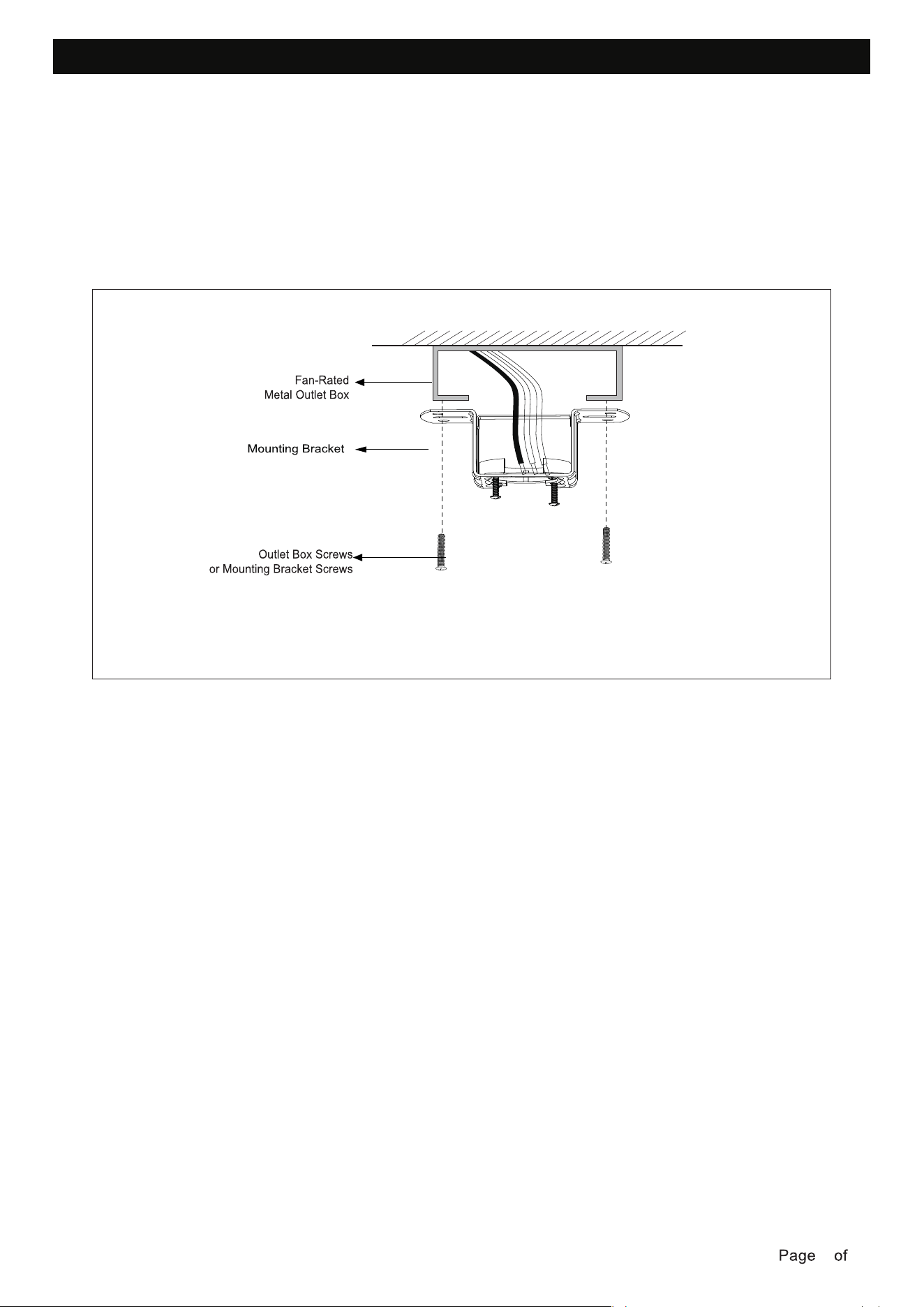
INSTALLING MOUNTING BRACKET
Before you begin installing the fan, turn off circuit breakers and wall switch to fan supply line leads.
metal outlet box.
Use outlet box screws (provided with outlet box) when securing the mounting bracket to the fan-rated
To reduce the risk of electrical shock, the fan must be installed with an isolating wall control/switch.
WARNING: Failure to disconnect the power supply prior to installation may result in serious injury.
250215
7 15
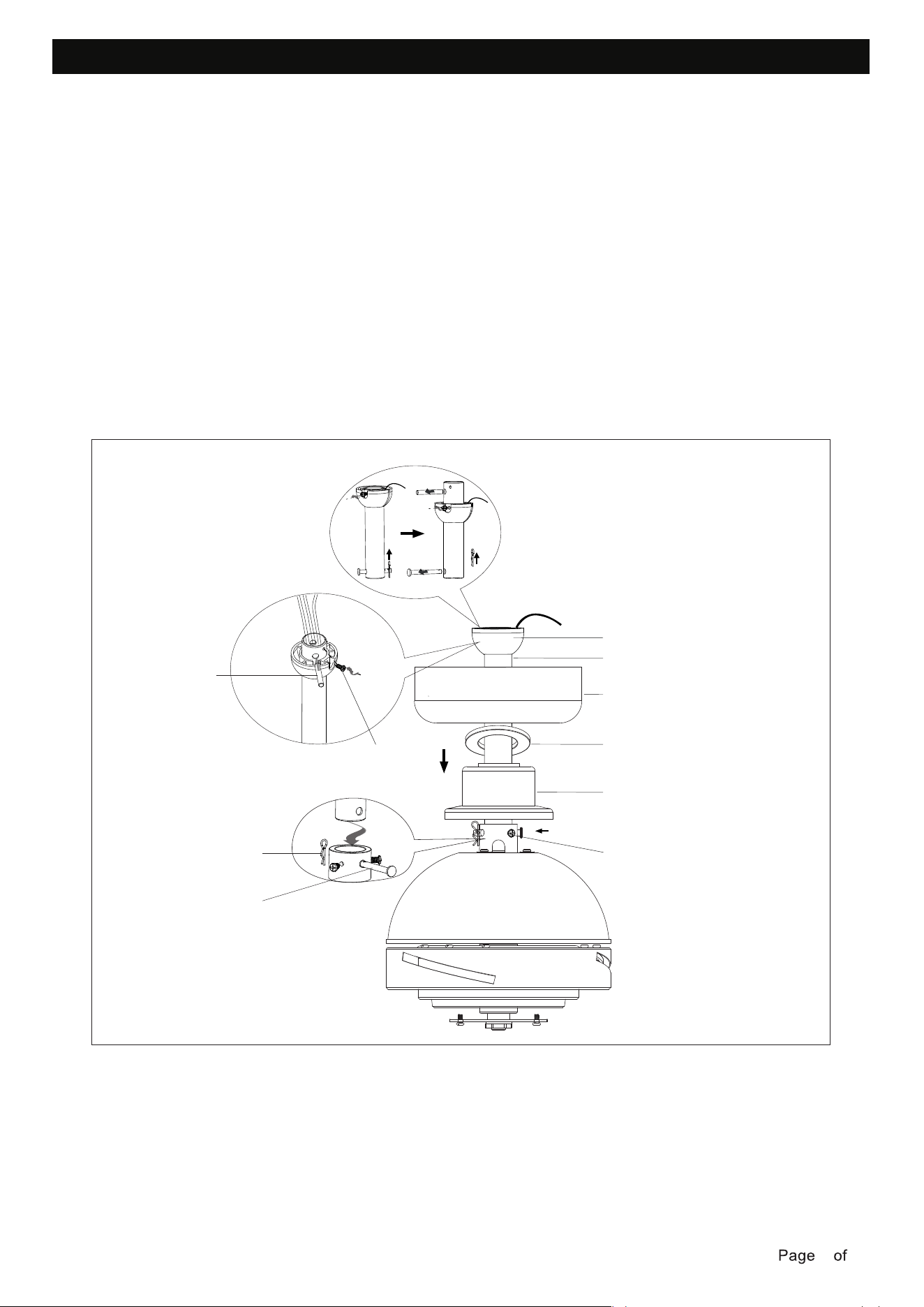
DOWNROD ASSEMBLY
Loosen the set screw and remove the cross pin from the hanging ball assembly.
Carefully feed the fan motor assembly wires up through the downrod.
Thread the downrod into the fan motor assembly coupling. Line up the holes and replace the downrod
pin and lock pin. Tighten the security screws on the fan motor assembly.
Place coupling cover, canopy cover and canopy on the downrod between hanging ball and the fan motor
correct position, the set screw is tight, and the wires are not twisted.
assembly. Carefully replace the hanging ball onto the downrod, and ensure that the cross pin is in the
WARNING: Failure to tighten set screw on downrod ball completely could result in fan becoming loose
and possibly falling.
Lock pin
Security screw
Coupling cover
Canopy cover
Canopy
Downrod
Cross pin
Set screw
Hanging ball
Downrod pin
Loosen the lock pin and remove the downrod pin from the end of hanging ball assembly and save all
parts.
250215
8 15
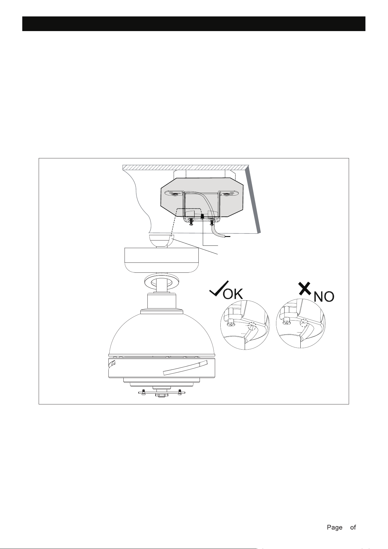
HANGING THE FAN MOTOR ASSEMBLY
Lift the fan assembly into position, and place the hanger ball into the mounting bracket.
Rotate the fan assembly until the check groove drops into the registration slot and seats firmly.
The downrod should not rotate if this is done correctly.
NOTE: The entire fan motor assembly should not rotate when seated properly.
WARNING: Failure to seat tab in the notch of the hanging ball could cause damage to electrical wires
WARNING: To avoid possible shock, do not pinch wires between the downrod/hanging ball .
and possible shock or fire hazard,
Check groove
Registration slot
Check
groove
Registration slot
Check
groove
Registration slot
250215
9 15
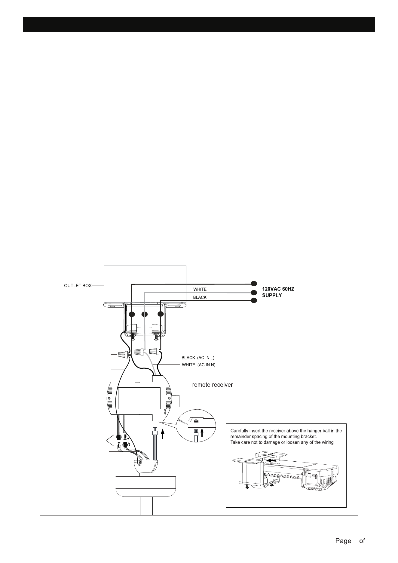
MAKING THE ELECTRICAL CONNECTIONS
WARNING: To avoid possible electrical shock, be sure power is turned off at the main fuse box
before installing.
• Insert the narrow end of the receiver (flat side towards the ceiling) into the mounting bracket
until it rests on top of the ball/downrod assembly.
Follow this wiring diagram.
When fan is secured in place on the mounting bracket, make electrical connections as follows.
mounting bracket and hanging ball to ground wire (bare copper) from the outlet box. Make sure to
use wire nuts provided with your fan.
• Connect the wires from the fan motor assembly to the receiver with the wire connectors, push
them together.
outlet box. Separate black wires on one side of the box, white and ground wires on the other side.
• Connect BLACK wire from the outlet box to BLACK wire (AC IN L) from the receiver.
• Connect WHITE wire from the outlet box to WHITE wire (AC IN N) from the receiver.
• Connect GREEN ground wire from the remote receiver and GREEN ground wire from the
NOTE: After wire connections have been made, turn leads upward and carefully push them into the
NOTE: If installing extension downrod, you can plug the light extension lead wires and motor extension
lead wires into the lead wires of fan motor assembly.
NOTE: Spread the wires apart so that the light wires are on one side of the mounting bracket and
the motor wire is on the other side.
Wire nut
GREEN GROUND
Connect
BARE COPPER GROUND
MOTOR WIRES
UP LIGHT WIRES
DOWN LIGHT WIRES
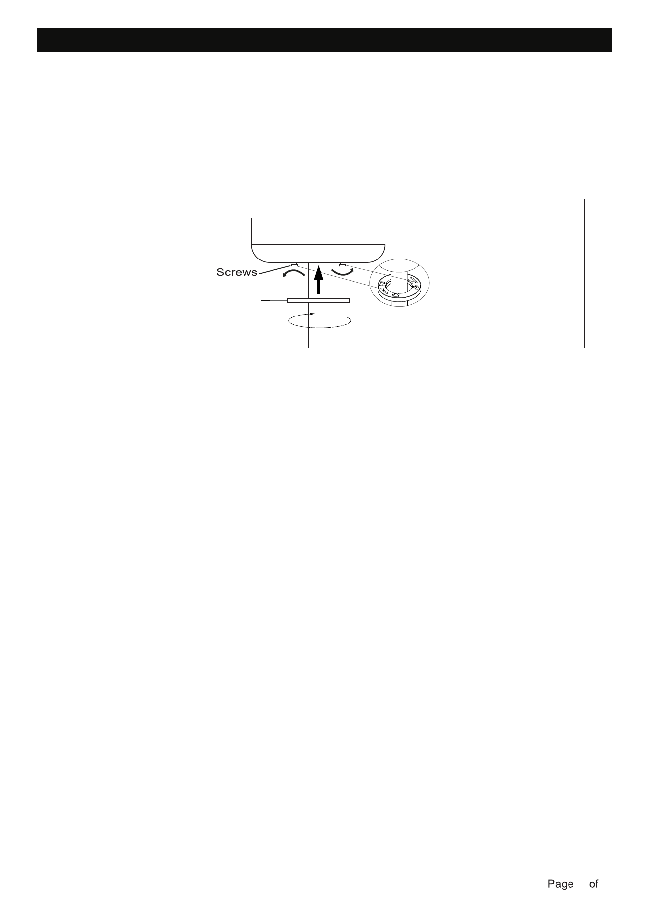
INSTALLATION OF THE CANOPY
• Loosen the 2 screws at the bottom of the mounting bracket.
• Slide the canopy up to the mounting bracket and align the key holes on the canopy with the
screws on the mounting bracket. Turn the canopy until it locks into place with the narrow section
of the key holes and secure it by tightening the two screws. Avoid damaging the electrical wiring
prepared previously.
• Turn the canopy cover until it locks into place with the narrow section of the key holes and secure.
Canopy cover
250215
10 15
250215
11 15
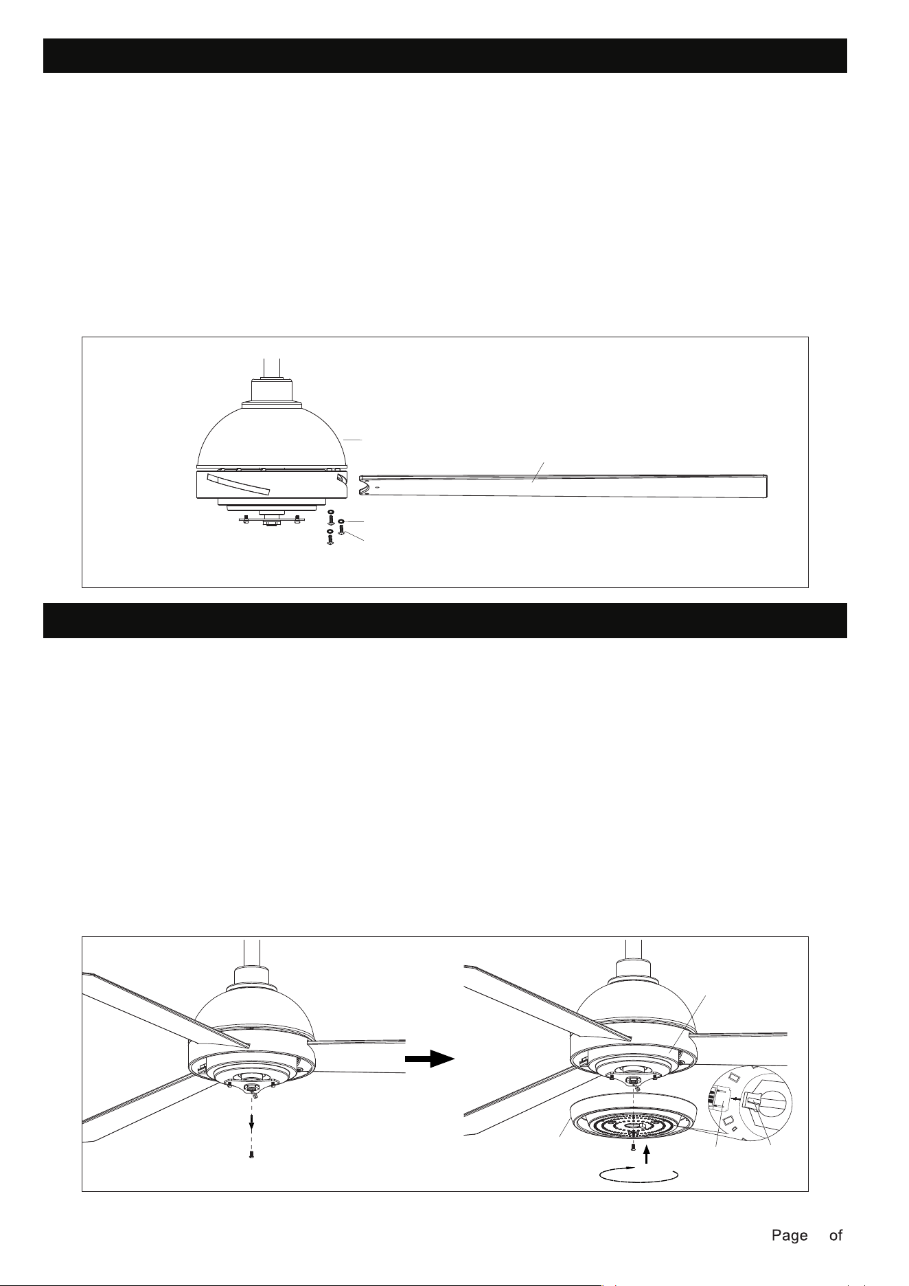
BLADES INSTALLATION
• Insert the blade into the slot of rotating member of fan motor assembly.
INSTALLING LIGHT KIT
• Loosen the two screws one half a turn from the key slots, and unscrew the third screw from the
circular hole.
• Pass the light wires from fan motor assembly through light kit.
• Attach the light kit to the fan motor assembly. Align the key hole slots in the light kit with the 2
loosened screws in the fan housing plate. Turn the light kit clockwise and secure with the third
screw previously removed. Tighten all screws.
• Align and engage the holes of the blade to the fan motor assembly.
• Repeat the same process for the other blades.
NOTE: The smooth side of the fan blade faces the floor.
• Secure the blade to the fan motor assembly by tightening the 3 blade screws and 3 fiber washers .
Ensure all screws are tightened evenly to reduce the chance of warping or unbalancing. Take care
not to overtighten the screws, as this can damage the blades.
WARNING: To reduce the risk of personal injury, do not bend the blade during assembly or after
installation. Do not insert objects in the path of the fan blades.
Fan motor assembly
Fiber washers
Blade screws
Blade
Light kit
Male
connector
Female
connector
Fan housing
• Plug the male connector of the light kit to the female connector on the fan housing. The male
connect on the light kit can only be install in one direction. Both light kit and fan housing
connector should engage and snap in place. Any excess wire from the fan housing needs to
be push back to the center hole.
250215
12 15
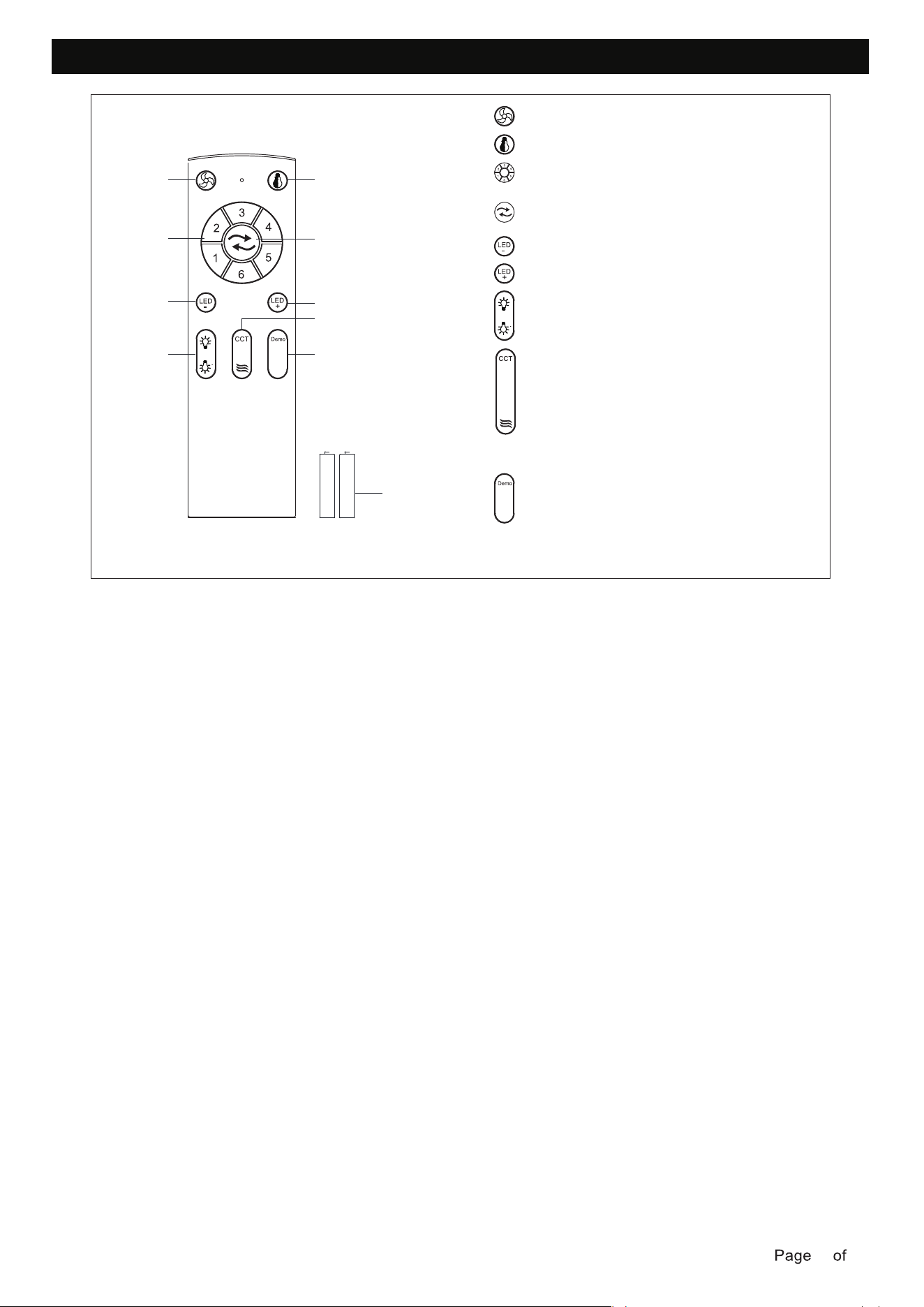
INSTALLING THE REMOTE CONTROL HOLDER
• Remove the remote control from the remote control holder.
• Locate a suitable wall or surface to fix the remote control wall holder.
• Slide the remote into the holder.
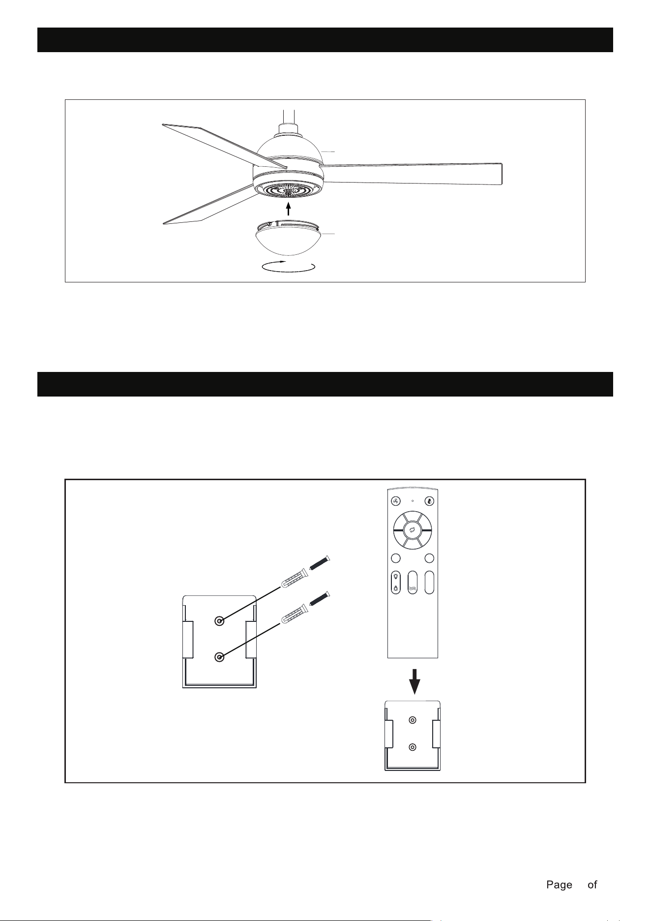
INSTALLATION GLASS SHADE
• Install the Lamp shade clockwise to the fan motor assembly .
Fan motor assembly
Lamp shade
1
2
3
4
5
6
LED
-
Demo
LED
+
CCT
250215
13 15
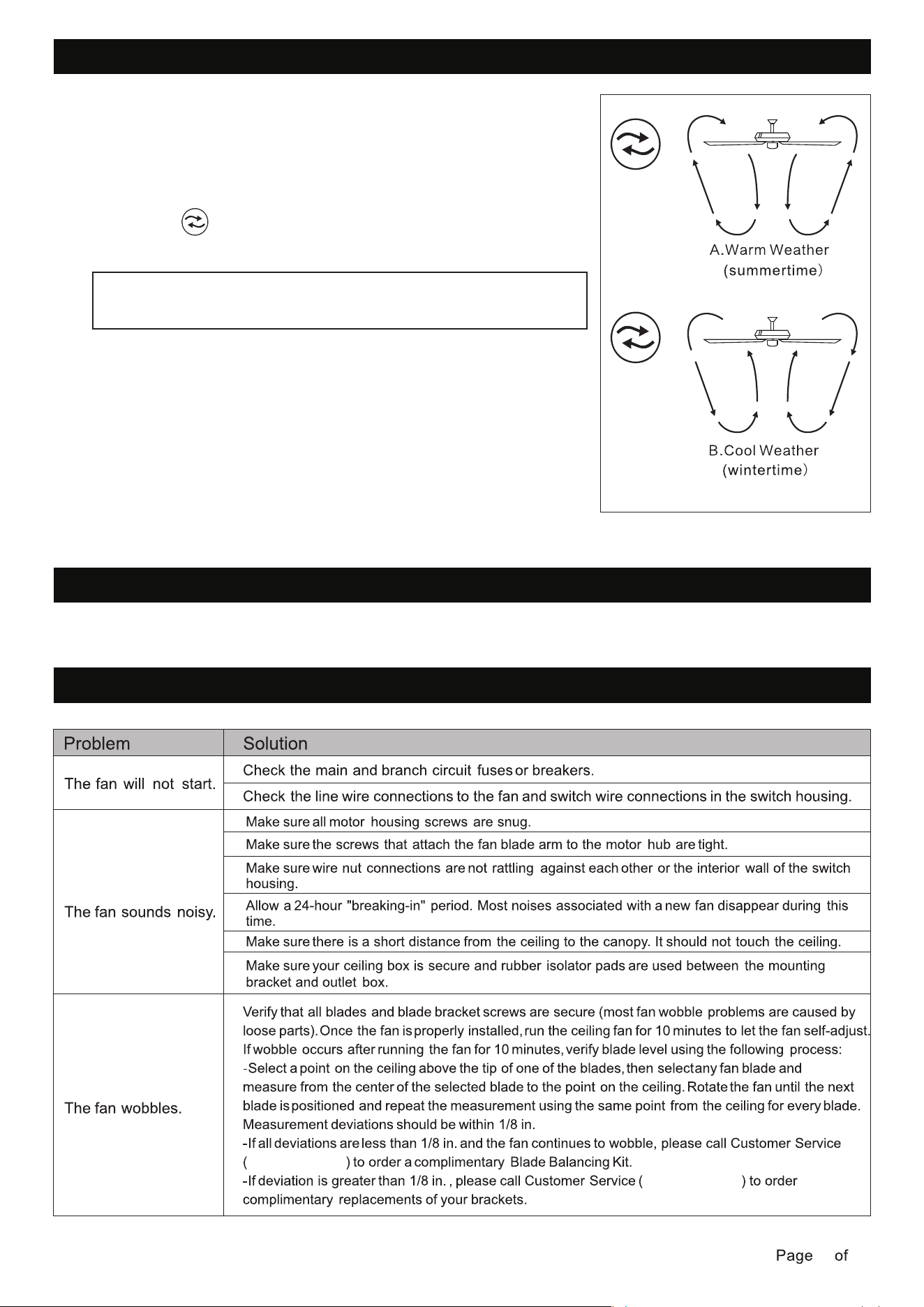
OPERATING YOUR TRANSMITTER
• Install AAA1.5V*2 battery.
• Store the transmitter away from excessive heat or humidity.
Learning code matching mode is used between REMOTE CONTROL and receiver. Turn on the supply
power within 5 seconds and press the REMOTE CONTROL“FAN ON/OFF" button for 3 seconds, it can
load normally after hearing a long sound “bee", which means learning successfully and it can works
normally.(PS: Learning mode is not accepted after turning “ON" the supply power for 5 seconds)
(To prevent damage to transmitter, remove the battery if not used for a long time).
1
1
-Fan ON/OFF
2 -Light ON/OFF
3 -Fan Speed 1~6
4 -Forward/Reverse
Summer / Winter Mode
5 -Brightness -
No. 6 is the highest speed
6 -Brightness +
7
-Up Light ON/OFF
8
-Down Light ON/OFF
-5CCT
Press to change the color temperature from 2700~
3000~3500~4000~5000~2700K, long press to
gradually change color temperature from 2700~5000K
9
Demo
Press the display function for which automatically
switches the color temperature every 5 seconds,
and press again to turn off the lights
-Natural wind
The fan will alternates through speeds 1-5 for every
5 seconds until the mode is canceled
10 Battery:
2*AAA (1.5V)
3
5
7
2
4
6
8
9
10
250215
14 15
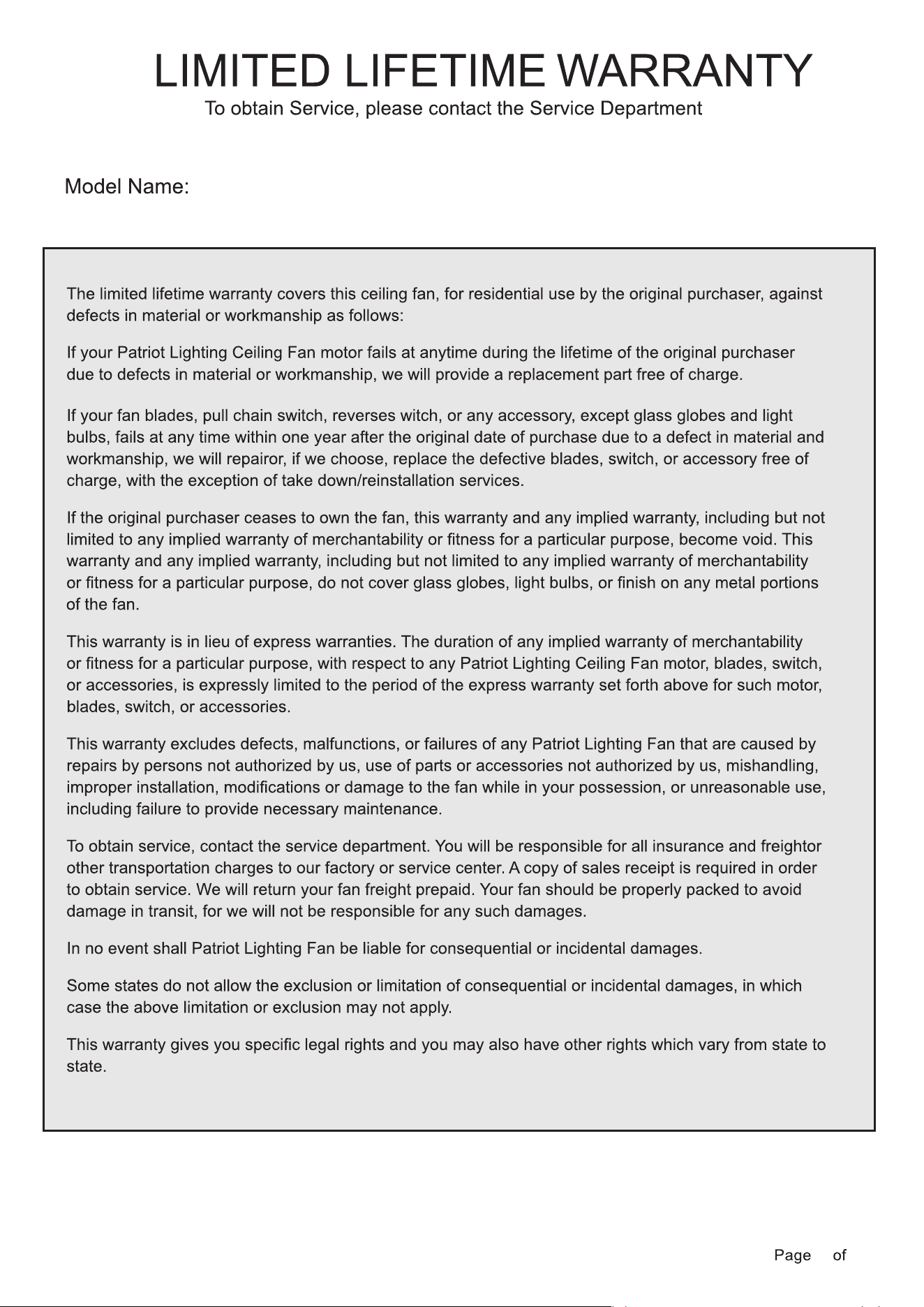
REVERSE SWITCH OPERATION INSTRUCTIONS
CARE AND MAINTENANCE
• To clean, turn off and wipe with a damp, non-abrasive cloth.
TROUBLESHOOTING
1-833-695-2045
1-833-695-2045
Turn on the power and check the operation of the fan.
The remote controls the fan speed and light.
A.Warm weather-(Forward)A downward airflow creates a cooling
effect.This allows you to set your air conditioner on a higher setting
without affecting your comfort.
B.Cool weather-(Reverse)An upward airflow moves warm air off of
the ceiling.This allows you to set your heating unit on a lowering
setting without affecting your comfort.
The appropriate speed settings for warm or cool weather depends
on factors such as the room size, ceiling height, and number of fans.
The switch controls the direction of the blades:
forward or reverse.
NOTE: Wait for the fan to stop before reversing the direction of
the blade rotation
52" Downrod Mount Ceiling Fan
250215
15 15
