Sku Number: 3553572
42" RGBW Integrated LED
Indoor Ceiling Fan
Model Number: 3553572
Remote Number: GE37106TX
Questions, problems, missing parts?
Before returning to your retailer, call our customer service at 1-888-543-1388
Monday – Friday 7:00 a.m. – 5:00 p.m. CST
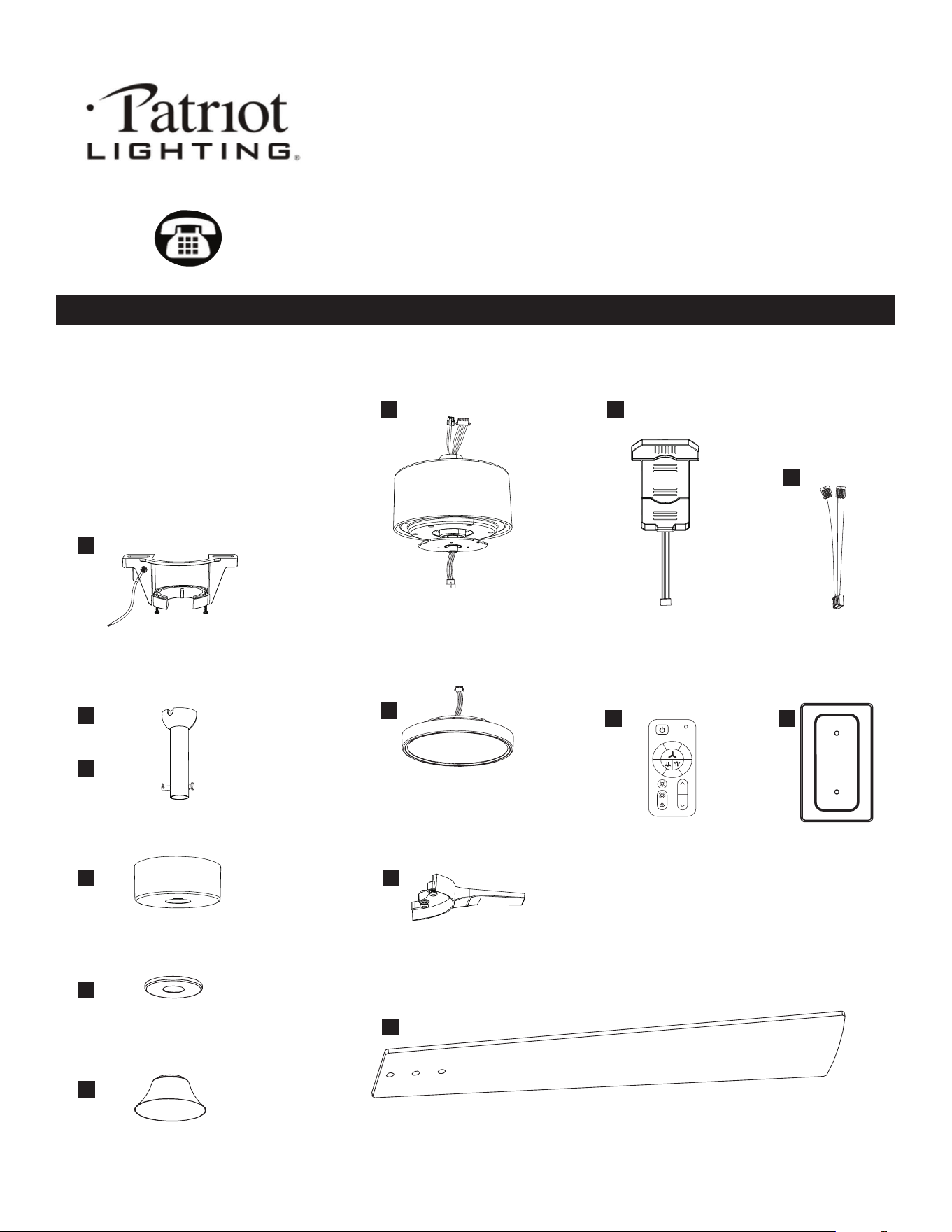
PACKAGE CONTENTS
DC motor
Energy efcient 30W
Reversible motor
6 Speed
3000 CFM, 220 RPM
Integrated LED
1000 lumens, 80 CRI
30,000 hours
42" diameter (fully assembled)
Net weight of fan: 7.605 vlb / 3.45 kg
A
B
C
D
E
F
J
L
K
M N
G
H
I
Mounting bracket x1
Downrod x1
Canopy x1
Canopy ring x1
Decorative cover x1
Blade x3
Blade arm x3
Fan motor housing x1 Remote control receiver x1
Remote control x1
Receiver wires x1
Remote control
back plate x1
Light kit x1
22
33
44
55
66
11
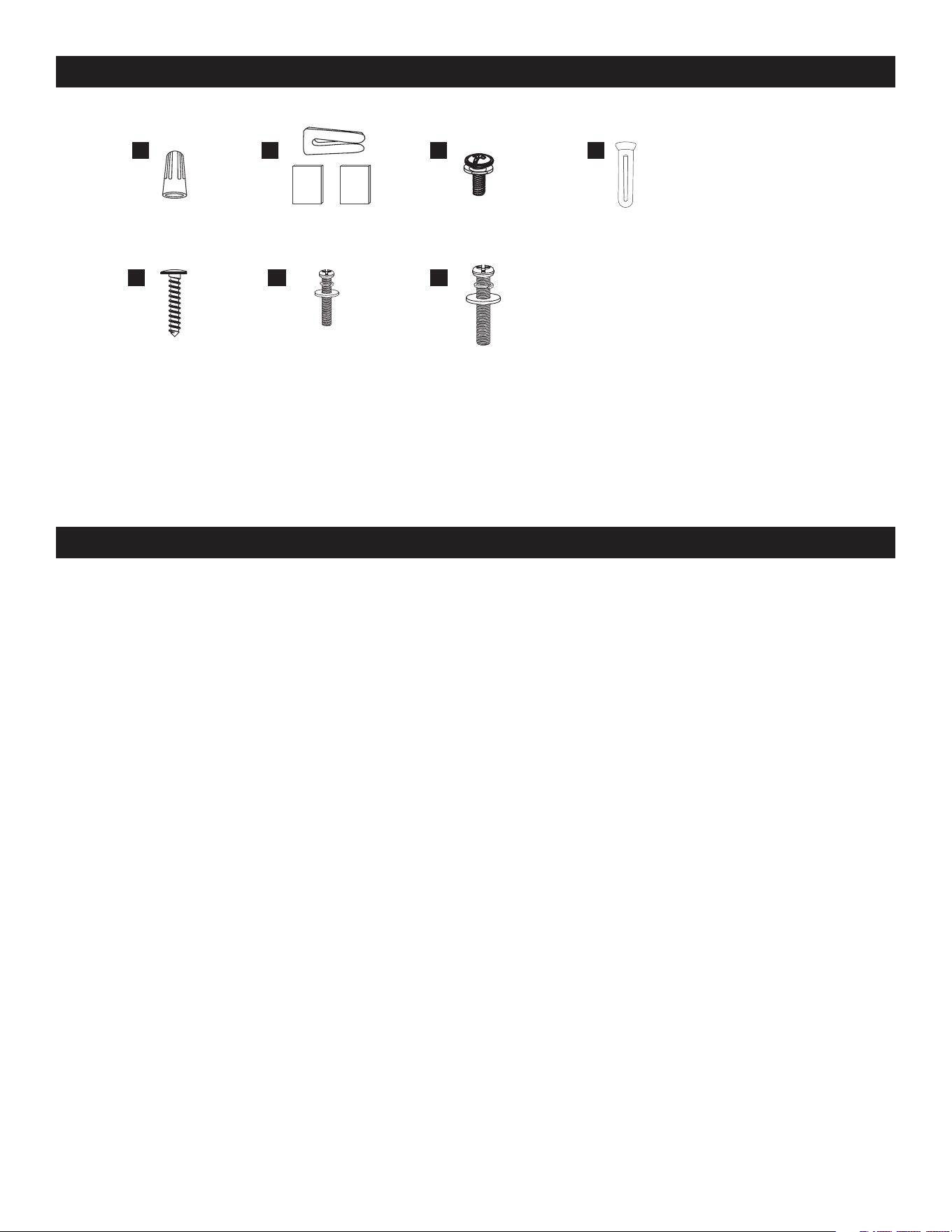
HARDWARE CONTENTS Note: Hardware not shown actual size.
AA
EE FF
BB
GG
CC DD
Wire nut x2
Remote control back
plate screws x2
Extra Junction Box
screws and washers
#8-32 x 1"
(2.54 cm) x2
Extra Junction Box
screws and washers
#10-24 x 1" (2.54 cm) x2
Blade arm
screws x10
Remote control back
plate screw anchors x2
Balancing kit x1
PREPARATION
Before beginning assembly, installation or operation of product, make sure all parts are present. Compare parts with package contents list and
diagram on previous page. If any part is missing or damaged, do not attempt to assemble, install or operate the product. Contact customer service
for replacement parts. Tools Required for Assembly (not included): Phillips screwdriver, Flathead screwdriver, Ajustable wrench, Electrical tape, Wire
cutter, Step ladder. (Do not use power tools for the installation to avoid damaging the screws/parts)
SAFETY INFORMATION
WARNING
• REMOVE AND IMMEDIATELY RECYCLE OR DISPOSE OF USED BATTERIES ACCORDING TO LOCAL REGULATIONS
AND KEEP AWAY FROM CHILDREN. DO NOT DISPOSE OF BATTERIES IN HOUSEHOLD TRASH OR INCINERATE.
• EVEN USED BATTERIES MAY CAUSE SEVERE INJURY OR DEATH.
• CALL A LOCAL POISON CONTROL CENTER FOR TREATMENT INFORMATION.
• CR2032 3V REPLACEABLE BATTERY.
• NON-RECHARGEABLE BATTERIES ARE NOT TO BE RECHARGED.
• DO NOT FORCE DISCHARGE, RECHARGE, DISASSEMBLE, HEAT ABOVE (60°C) OR INCINERATE
• DO NOT MIX OLD AND NEW BATTERIES, DIFFERENT BRANDS OR TYPES OF BATTERIES, SUCH AS ALKALINE,
CARBON-ZINC, OR RECHARGEABLE BATTERIES.
• REMOVE AND IMMEDIATELY RECYCLE OR DISPOSE OF BATTERIES FROM EQUIPMENT NOT USED FOR AN
EXTENDED PERIOD OF TIME ACCORDING TO LOCAL REGULATIONS.
• ALWAYS COMPLETELY SECURE THE BATTERY COMPARTMENT. IF THE BATTERY COMPARTMENT DOES NOT CLOSE
SECURELY, STOP USING THE PRODUCT, REMOVE THE BATTERIES, AND KEEP THEM AWAY FROM CHILDREN
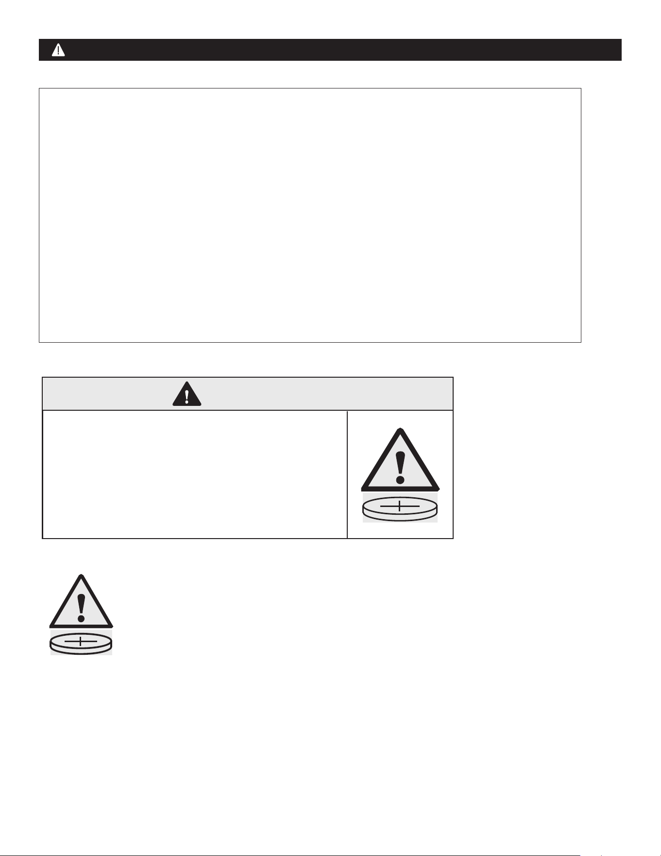
WARNING
INGESTION HAZARD:
This product contains a button cell or coin battery.
• INGESTION HAZARD: This product contains a button cell or
coin battery.
• DEATH or serious injury can occur if ingested.
• A swallowed button cell or coin battery can cause Internal Chemical
Burns in as little as 2 hours.
• KEEP new and used batteries OUT OF REACH of CHILDREN.
• Seek immediate medical attention if a battery is suspected to be
swallowed or inserted inside any part of the body
WARNING
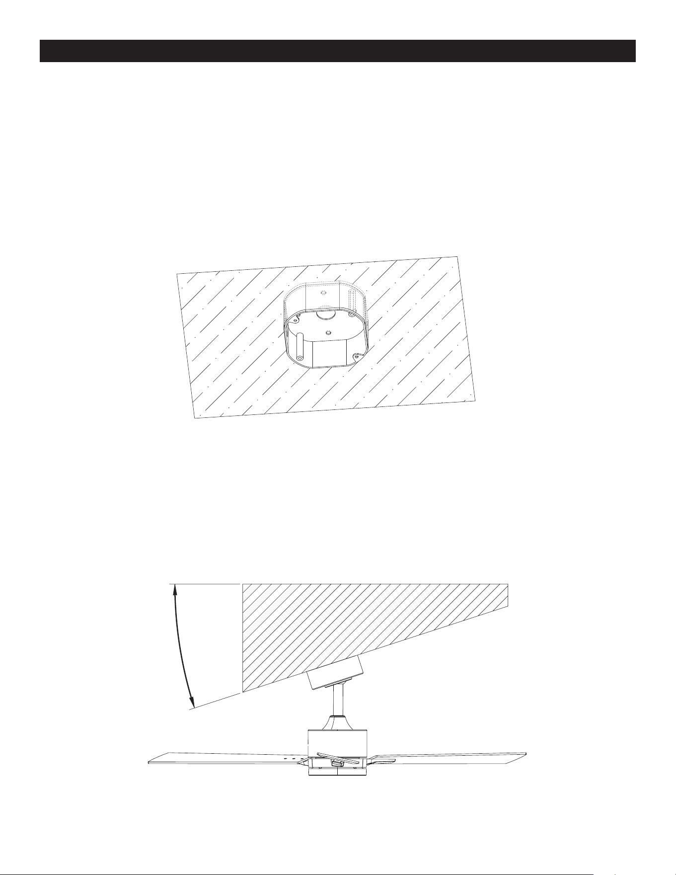
PRE-INSTALLATION
Outlet Box:
Fan must be able to be secured to a fan-rated outlet box. If none exists, contact a qualied electrician for installation.
NOTE: Fan can be mounted on a sloped ceiling up to a maximum angle of 15 degrees.
WARNING: To reduce the risk of re, electric shock, or personal injusry, mount to outlet box marked "acceptable for fan support of
15.9/22.7/31.8 KG (35/50/70 LBS) or less" and use mounting screws provided with the outlet box. Consult a qualied electrician if
in doubt.
15°
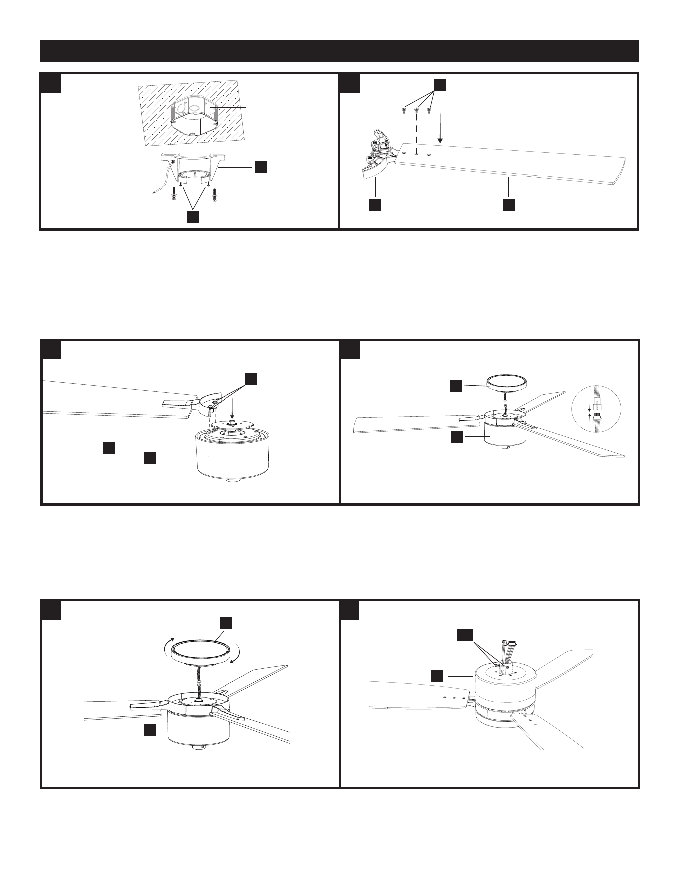
1. ATTACH THE MOUNTING BRACKET TO THE OUTLET BOX.
Secure the mounting bracket (A) to the ceiling outlet box with the screws
and washers provided with your outlet box.
Loosen (do not remove) the 2 mounting bracket screws (SS).
NOTE: Extra junction box screws #8-32 x 1” (2.54 cm) and washers (FF)
and #10-24 x 1” (2.54 cm) and washers (GG) found in bag “AA” included
if needed.
2.1 ATTACH THE BLADES
Secure the blade arm (I) to the fan blade (J) using the blade arm screws
(CC) from the accessory bag "BB". Repeat for the other 2 blades.
2.2 ATTACH THE BLADES
Line up the assembled blade (J) to the motor housing (G) between the 2
arrows , as shown, and attach using the pre-installed blade screws and
washers (ZZ). Repeat for the remaining 2 blade arms.
3.1 ATTACH THE LIGHT KIT
Connect the wires from the light kit (H) to the wires from the fan motor
housing (G).
3.2 ATTACH THE LIGHT KIT
Attach the light kit (H) to the fan motor housing (G) by twisting clockwise
until tight.
4.1 ATTACH THE DOWNROD TO THE FAN MOTOR HOUSING
Turn the fan over and loosen the 2 set screws (QQ) on the fan motor
housing (G).
IINSTALLATION
A
CC
I J
SS
1 2
2 3
3 4
QQ
G
H
H
G
J
G
ZZ
G
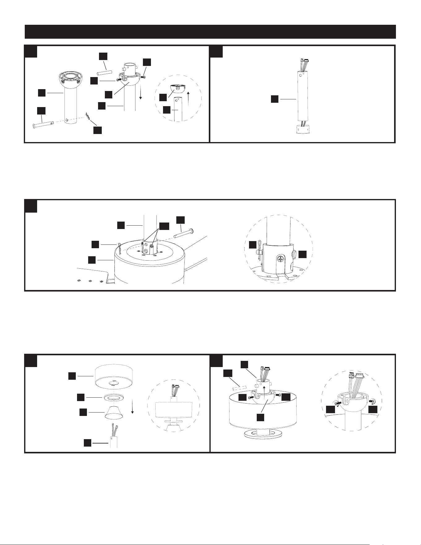
4.2 ATTACH THE DOWNROD TO THE FAN MOTOR HOUSING
Remove the locking pin (PP) and the hanging pin (OO) from the
downrod (C).
Remove the hanger ball (B) from the downrod (C) by removing the hanger
ball screws (NN) and (VV), and removing the cross pin (MM); then slide
the hanger ball (B) off the downrod (C).
4.3 ATTACH THE DOWNROD TO THE FAN MOTOR HOUSING
Carefully feed the motor housing wires up through the downrod (C).
4.4 ATTACH THE DOWNROD TO THE FAN MOTOR HOUSING
Insert the downrod (C) into the motor housing (G). Align the holes and
reinstall the hanging pin (OO) and secure with the locking pin (PP).
Tighten the set screws (QQ).
NOTE: If you feel resistance while pushing in the hanging pin, push cable
wires aside.
CAUTION: To avoid damage and to ensure a wobble-free operation,
the downrod and motor housing set screws must be fully tightened until
you fell resistance.
WARNING: Failure to properly install the motor housing locking pin
could result in the fan becoming loose and possibly falling.
5.1 ATTACH THE CANOPIES TO THE DOWNROD
Slide the decorative cover (F) onto the downrod (C). Then slide the canopy
ring (E) and the canopy (D), both facing upwards, onto the downrod (C).
5.2 ATTACH THE CANOPIES TO THE DOWNROD
To reinstall the hanger ball (B), slide it onto the downrod (C) and reinsert
the cross pin (MM) into the large hole. Slide the hanger ball (B) up so that
the cross pin (MM) is secured in the groove, ensuring the screw holes are
aligned correctly, larger screw (VV) should align with the hole in the down-
rod (C) and screw in both screws (NN) and (VV).
NOTE: Ensure wires are not twisted.
INSTALLATION - CONTINUED
4
4
5 5
4
CAUTION: A losse screw could result in wobbling of the fan.
C
PP
G
C
C
C
C
B
B
VV
MM
NN
OO
OO
OO
PP
QQ
PP
D
C
MM
VV
NN
VV NN
E
F
C
B
6 6
6.1 HANG THE FAN ON THE BRACKET
Lift the assembled fan to the ceiling and place the hanger ball (B) into the
mounting bracket (A) opening.
CAUTION: To prevent damage to the fan, always lift up the fan by the
downrod or motor housing.
6.2 HANG THE FAN ON THE BRACKET.
Rotate the assembled fan clockwise until the groove (TT) on the hanger
ball (B) drops into the slot (UU) on the bracket (A) and sits rmly. The
hanger ball (B) should no longer be able to rotate if this is done correctly.
CAUTION: failure to align groove on ball with ridge could result in
wobbling.
7 7
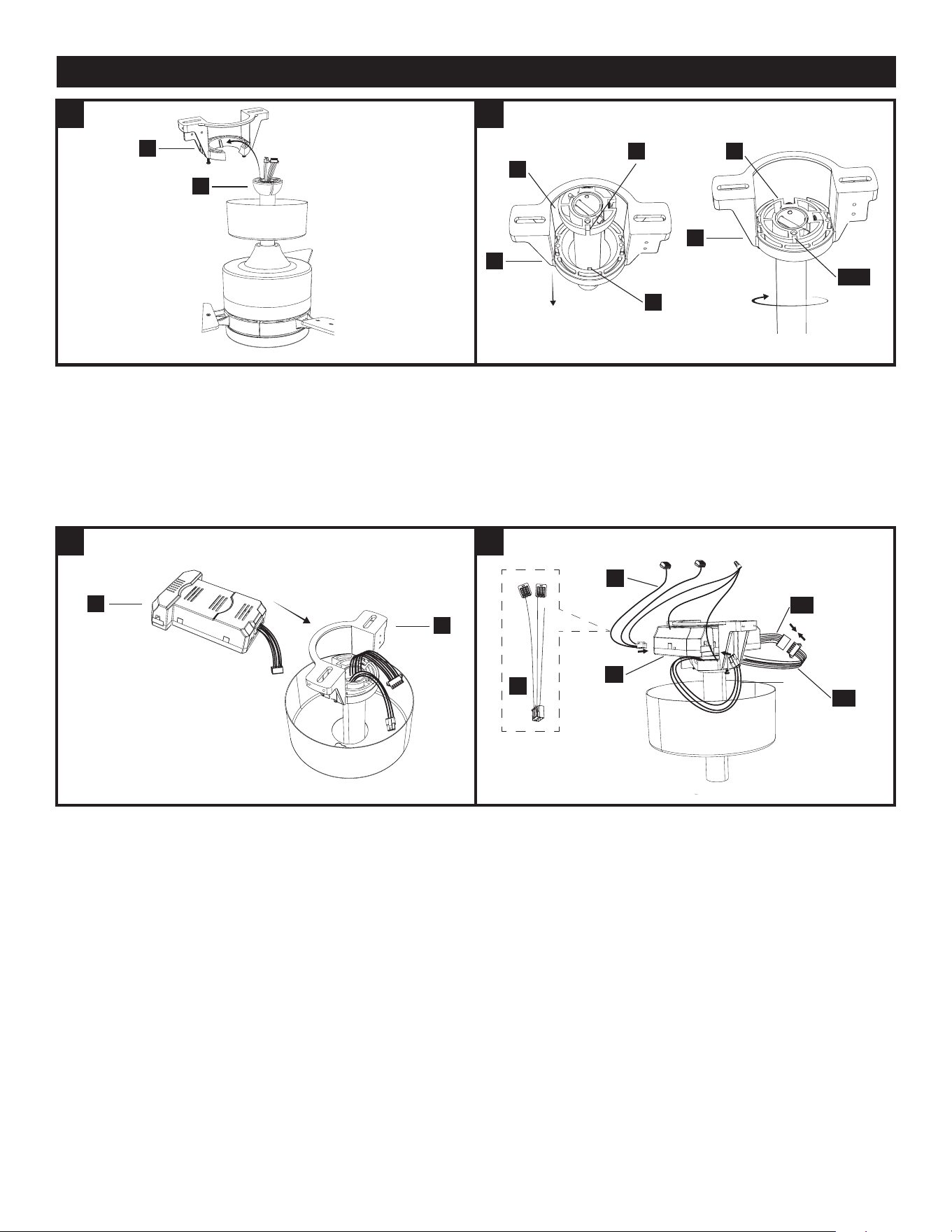
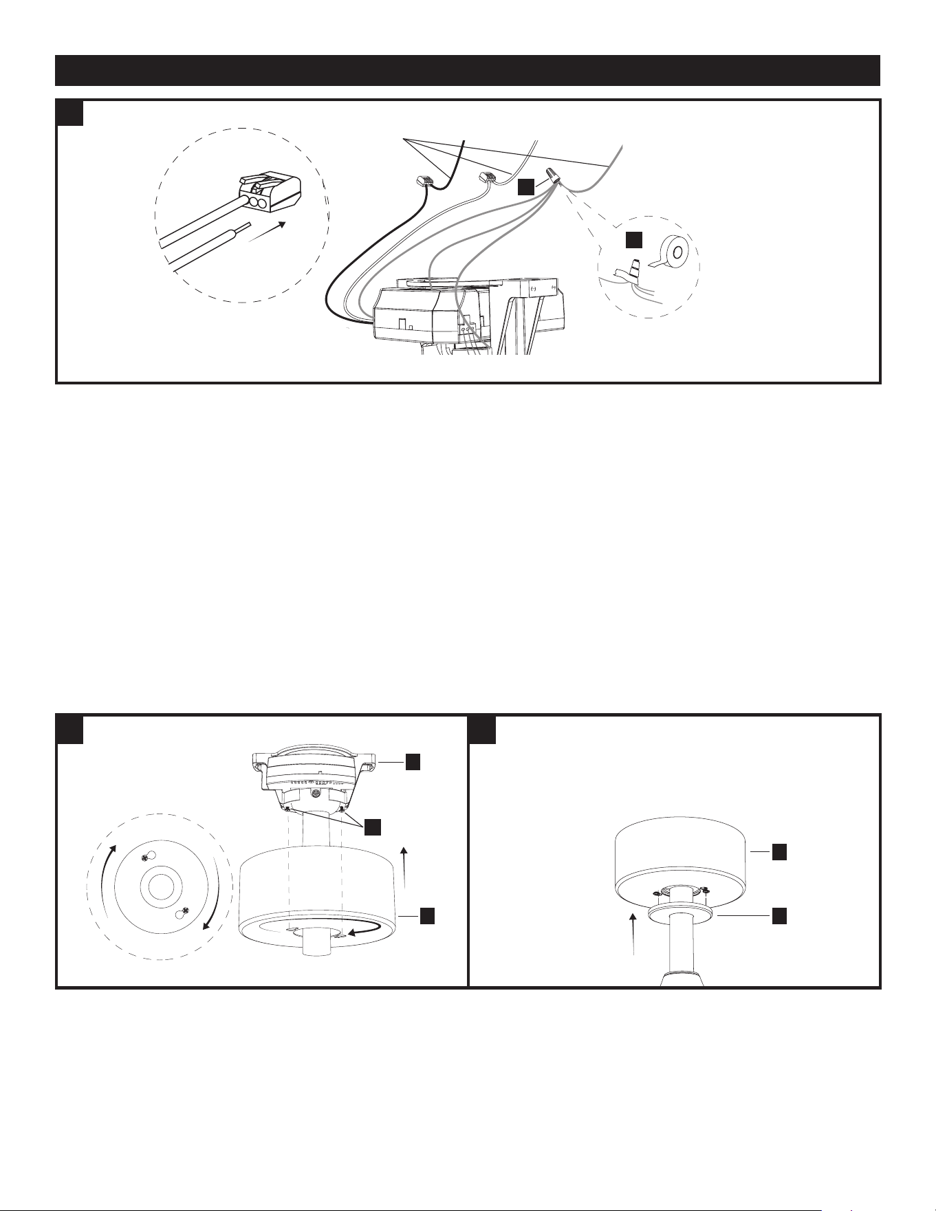
7.1 WIRE THE FAN
Insert the receiver (K) as shown, into the mounting bracket (A) .
7.2 WIRE THE FAN
Connect the receiver wires (L) to the receiver (K) as shown.
Connect the motor housing wires (WW) to the receiver as shown and
connect the motor housing wires (XX) to the wires from the receiver as
shown.
K
A
L
XX
WW
L
K
INSTALLATION - CONTINUED
A
A
A
UU
TT/UU
B
B
TT
B
8
7
8
8.1 ATTACH THE CANOPIES
Attach the canopy (D) to the mounting bracket (A) by aligning the mounting
bracket screws (SS) with the canopy keyholes and twist, then tighten the
mounting bracket screws (SS).
NOTE: Optionally, if you’re having difculty attaching the canopy due to
the wires, connect the receiver wires (L) to the ceiling wires before
placing receiver (K) into the mounting bracket (A), and tuck the wire
connections into the outlet box.
8.2 ATTACH THE CANOPIES
Slide the magnetic canopy ring (E) up to attach to the canopy (D).
7.3 WIRE THE FAN
Connect the ceiling wires to the receiver wires as follows:
Insert the hot (black) wire from the ceiling into one of the free holes of the
black wire quick connect from the receiver, lift the tab and push the wire in all
the way, after wire is inserted, push tab down. Gently tug on wire to ensure it
is secure in connector.
Insert the neutral (white) wire from the ceiling into one of the free holes of the
white wire quick connect from the receiver, lift the tab and push the wire in all
the way, after wire is inserted, push tab down. Gently tug on wire to ensure it
is secure in connector.
Connect all ceiling fan ground wires to ceiling ground wire, as shown, using
the wire nut (AA) found in bag "AA" and wrap it with electrical tape.
If your ceiling does not have a ground wire, consult a qualied electrician.
NOTE: After connecting the wires, spread them apart so that the ground /
white wires are on one side and the black wires are on the other side.
WARNING: All wiring must be in accordance with the National Electrical
Code, ANSI/NFPA 70. If wires at the installation site are any
other color than what is listed here, have this fan installed by a qualied
electrician.
WARNING: The ceiling fan must be grounded. If there is no ground wire
present on the installation site (example, from the ceiling), STOP the
installation immediately and consult a qualied electrician.
INSTALLATION - CONTINUED
Ceiling
wires
Black White Ground
AA
AA
SS
A
D
E
D
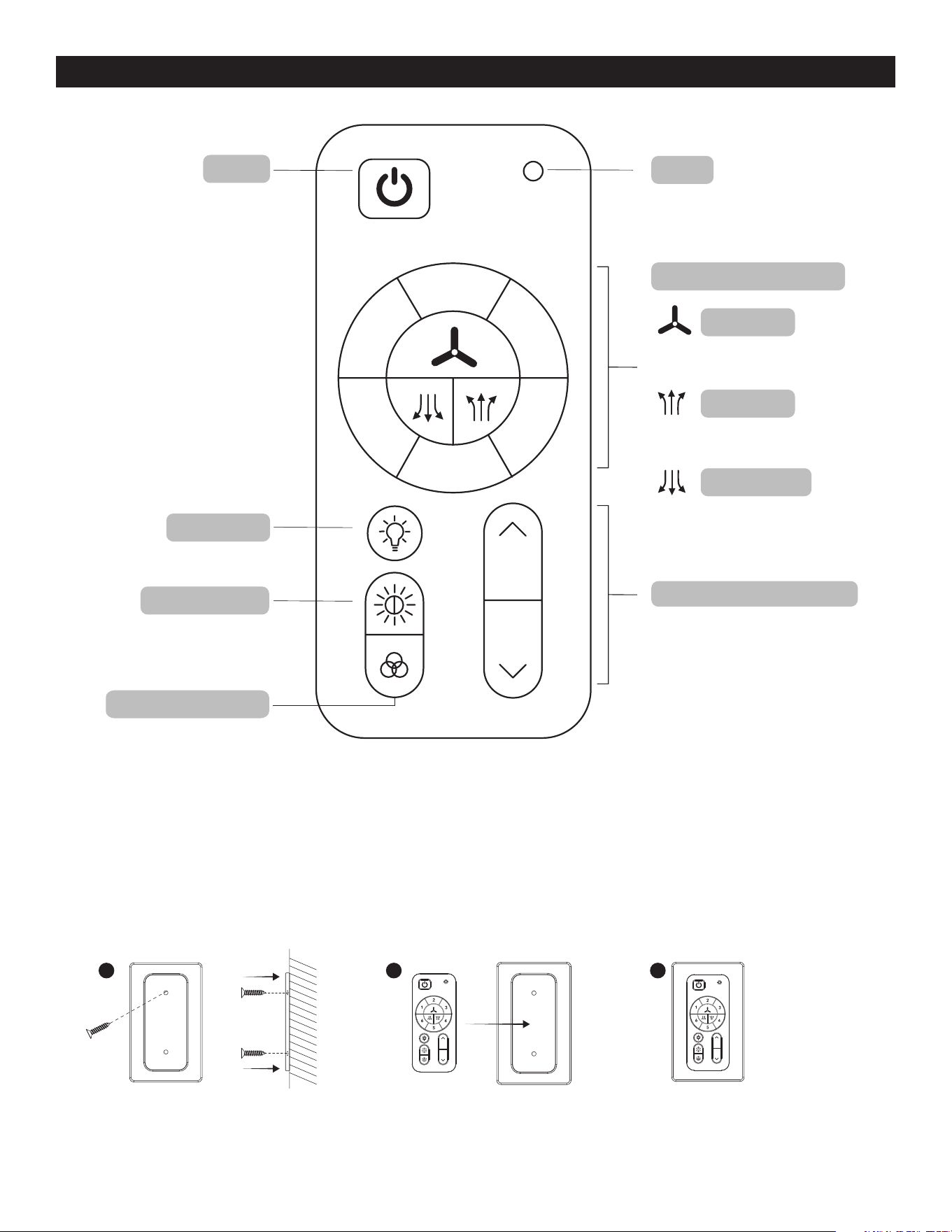
FAN AND REMOTE CONTROL OPERATION
1 2 3
Use accessories (DD and EE) found in bag to mount the
magnetic plate to preferred location.
NOTE: Remote uses 1 CR2032 button cell battery (included).Remove the plastic
tab on battery door before using remote. When replacing the battery, ensure the
battery door is closed all the way (you will hear a click).
NOTE: The device has been evaluated to meet RF exposure requirements.
The device can be used in portable exposure conditions without restriction.
This equipment complies with FCC radiation exposure limits set forth for an uncontrolled environment.
Blue LED indicator light will illuminate
when any button is pressed
Press button to turn fan
and light on or o
Note: Fan and light will
turn on to last state
Press button to turn light on or o
Push button to cycle through 6
Ambient White colors, Daylight,
Cool White, Natural White, Warm
White, Soft White or Sunset Glow
Push button to cycle through 7 preset
RGB colors Red, Orange, Yellow,
Green, Cyan, Blue or Magenta
Press button to turn fan on or o
Press button to switch fan’s rotation
upward to circulate rising warm air
Press button to switch fan’s rotation
downward for a cool downdraft
LED
power
light on/o
Tunable white
7 preset RGB colors
fan on/o
fan air up
fan air down
#1-6: 6 fan speed levels
Push (do not hold) buttons up
or down to increase or decrease
brightness
light dimmer up and down
2
3
4
5
6
1
Remote control SKU#:
GE37106TX

CARE AND MAINTENANCE
• The fan’s natural movements may cause some connections to come loose. A clicking or rattling noise is a certain sign of loosening screws. C
heck the support connections, brackets and blade attachment twice a year, and tighten all screws as necessary.
• Make sure to disconnect the fan from the power supply before servicing or cleaning.
• Clean your fan periodically. Use only a damp cloth, never use solvents, and dust with a soft cloth or brush.
• You will never need to oil your fan; its permanently sealed bearing will prevent noise.
• Do not operate when product is damaged. Discard fan or return to an authorized service facility for inspection and/or repair.
• Total light xture wattage is 14 watts; do not attempt to replace LED.
TROUBLESHOOTING
PROBLEM SOLUTION
1. Fan/Light does not start. • Ensure wall switch is turned on.
• Check all fuses/circuit breakers.
• Turn off electrical power and ensure the wiring is correct and connectors secured,
as shown in step 7 of assembly.
• Conrm that the remote is working; LED indicator light should illuminate when any
button is pressed.
• If fan/light still will not start, contact a qualied electrician. Do not attempt to
troubleshoot internal electrical connections yourself.
2. Fan is noisy. • Allow a 24-hour “break in” period. Any level of noise louder than ambient levels should disap-
pear during that time.
• Check the electrical outlet box and ensure it is securely fastened.
• Check all screws/wire connections on the fan to ensure they are securely fastened.
• Use of an unapproved light dimmer or wall control can cause the fan to act irregularly and
produce excess noise. Check to ensure that if installed, the wall control is approved for ceiling
fan use; however, it is not suggested to use a dimmer switch with the fan.
3. The fan moves backwards and forwards
when turned on.
• This is a normal start-up procedure for DC motor fans. The partial movement during
start-up is the result of the DC motor aligning the internal magnetic poles for proper
motor operation. This design saves electricity and allows the fan to operate much more quietly
than standard AC motor fans.
4. Fan does not move much air. • Check the direction of the fan blades when running. If needed, change the direction of the fan
blades to ensure the ceiling fan is moving air in the desired direction.
• Ensure no household items are obstructing the airow of the ceiling fan.
• Check to ensure the ceiling fan is appropriate for the size of the room in which it is installed.
5. Fan shakes or wobbles. • A small amount of wobble is typical and acceptable and is not indicative of a defect.
Run fan for at least 10 minutes before verifying level of wobble.
• Ensure the electrical outlet box and hanging bracket are securely fastened, as shown
in step 1 of assembly.
• Ensure the groove in the hanger ball is properly sitting in the bracket slot; if not, turn
hanger ball clockwise until ball drops into the slot, as shown in step 6 of assembly.
• Install the included balancing kit (CC). If undesired movement persists, simply change the
location of the balancing kit (CC) until the excess movement ceases.
6 .Remote control is not working • Ensure plastic tab is removed from the battery compartment.
• Ensure batteries are installed correctly in remote.
• Ensure the remote/receiver are paired. If the batteries are new and the LED indicator
light is working, but the fan and/or light are still not working, the remote may have become
un-paired. To pair the remote and fan, press the main on/off red button on the remote 3 times
within one minute.
• Ensure the wires from the receiver are correctly connected to the house wiring and
ceiling fan wires, as shown in step 7 of assembly.

FCC Responsible party:
Globe Electric
2264 East 6th Street
San Bernardino, CA 92410
www.globe-electric.com
FCC STATEMENT
READ AND SAVE THESE INSTRUCTIONS
Most electrical accidents are caused by carelessness or ignorance. If you combine a basic knowledge of electricity, a healthy
respect for it, and a dose of common sense, you can safely tackle many household electrical repairs. Here are some basic
guidelines for working with electricity:
Before working on a circuit, go to the main service panel and remove the fuse or trip the breaker that controls that circuit. Tape
a sign to the panel warning others to leave the circuit alone while you work.
Before touching any wire, use a voltage tester to make sure it’s not live.
Whenever you check for voltage in a receptacle, check both outlets – each may be controlled by a separate wiring circuit.
When replacing fuses, turn off the main power first. Make sure your hands and feet are dry, and place one hand behind your
back to prevent electricity from making a complete circuit through your chest. Touch a plug fuse only by its insulated rim.
Remove cartridge fuses with a fuse puller.
Use tools with insulated handles and ladders made of wood or fiberglass.
Keep dry-chemical fire extinguishers in the kitchen, basement, and workshop.
Never disable grounding devices. Make sure that all appliances requiring grounding are properly grounded, and that the
electrical system itself is properly grounded.
Meet or exceed all electrical code requirements that cover the work you are doing.
Always work with enough light to see what you are doing; it’s easy to make mistakes when you’re working in dim light.
If in doubt, consult a qualified electrician.
This device GE37106TX complies with Part 15 of the FCC Rules. Operation is subject to the following two conditions: (1) this
device may not cause harmful interference, and (2) this device must accept any interference received, including interference
that may cause undesired operation.
Changes or modifications to this unit not expressly approved by the party responsible for compliance could void the user’s
authority to operate the equipment.
Note: This equipment has been tested and found to comply with the limits for aClass B digital device, pursuant to Part 15 of
the FCC Rules. These limits are designed to provide reasonable protection againstharmful interferencein a residential
installation. This equipment generates, uses and can radiateradio frequency energyand, if not installed and used
in accordance with the instructions, may causeharmful interferenceto radio communications. However, there is no
guarantee that interference will not occur in a particular installation. If this equipment does causeharmful interferenceto
radio or television reception, which can be determined by turning the equipment off and on, the user is encouraged to try
to correct the interference by one or more of the following measures:
- Reorient or relocate the receiving antenna.
- Increase the separation between the equipment and receiver.
- Connect the equipment to an outlet on a circuit different from that to which the receiver is connected.
- Consult the dealer or an experienced radio/TV technician for help.
CAN ICES (B)/NMB (B)
WARNING: to reduce the risk of fire or electric shock, do not use this fan with any solid-state speed control device.
WARNING: to reduce the risk of personal injury, do not bend the blade brackets when installing the brackets, balancing the
blades, or cleaning the fan. Do not insert foreign objects in between rotating fan blades.
WARNING: to reduce the risk of fire, electric shock, or personal injury, mount to outlet box marked “acceptable for fan support
of 15.9/22.7/31.8 kg (35/50/70 lbs) or less” and use mounting screws provided with the outlet box.
CAUTION: to reduce the risk of electric shock, disconnect the electrical supply circuit to the fan before installing light kit.
Questions, problems, missing parts?
Before returning to your retailer, call our customer service at 1-888-543-1388
Monday – Friday 7:00 a.m. – 5:00 p.m. CST
WARRANTY
08-101-24
3-YEAR LIMITED WARRANTY
What is covered
This product is guaranteed to be free of factory defective parts and workmanship for a period of
3 years from date of purchase. Purchase receipt is required for all warranty claims.
What is not covered
This guarantee does not include repair service, adjustment and calibration due to misuse, abuse or negligence. Unauthorized
service or modication of the product or of any furnished component will void this warranty in its entirety. This warranty does not
include reimbursement for inconvenience, installation, setup time, loss of use, unauthorized service, or return shipping charges.
This warranty is not extended to other equipment and components that a customer uses in conjunction with this product.
Model Min. Thickness of edges of blades (in./mm) Blade length (in./cm) RPM Speed at tip of blades (ft/s, m/s)
553572 0.188" (4.8mm) 16.53" (42cm) 220 39.92ft/s (12.17m/s)
