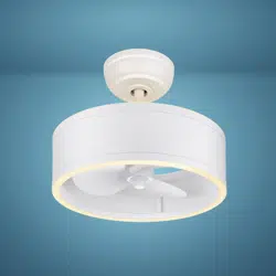
Model No.: F0127
ORIGINAL VAXCEL CEILING FAN LIMITED LIFETIME WARRANTY*
*for full limited lifetime warranty details please see final page of these instructions.
Safety Instructions
READ ALL SAFETY INFORMATION AND INSTALLATION INSTRUCTIONS BEFORE YOU BEGIN TO
INSTALL THE FAN AND SAVE INSTRUCTIONS.
•
All set screws of the fan must be checked and retightened where necessary before installation.
•
To reduce the risk of personal injury, do not bend the blade brackets when installing the brackets,
balancing the blades or cleaning the fan. Do not insert foreign objects between rotating fan blades.
•
Before changing the fan direction, turn off the fan and wait for the fan blades to stop completely.
•
The safeguards provided by these safety instructions and by the separate installation instructions
are not meant to cover all possible conditions and situations that may occur. It must be understood
that common sense, caution and care are factors which can not be built into this product.
•
These factors must be supplied by the person(s) installing, caring for and operating the fan.
WARNING
• TO AVOID RISK OF ELECTRIC SHOCK, BE SURE TO SHUT OFF POWER AT THE MAIN
FUSE OR CIRCUIT BREAKER BOX BEFORE INSTALLING OR SERVICING THIS
FIXTURE. TURNING OFF THE ELECTRICAL POWER BY USING THE LIGHT SWITCH
IS NOT SUFFICIENT TO PREVENT ELECTRICAL SHOCK.
•
TO REDUCE THE RISK OF INJURY, INSTALL THE FAN SO THAT THE BLADES ARE
AT LEAST 7 FEET (2.1 METERS) ABOVE THE FLOOR AND AT LEAST 18 INCHES
(0.5 METERS) FROM THE TIP OF THE BLADES TO THE WALL.
•
TO REDUCE THE RISK OF FIRE, ELECTRIC SHOCK, OR PERSONAL INJURY, MOUNT
TO OUTLET BOX MARKED "ACCEPTABLE FOR FAN SUPPORT" AND USE MOUNTING
SCREWS PROVIDED WITH THE OUTLET BOX.
•
THE INSTALLATION HAS TO BE IN ACCORDANCE WITH THE NATIONAL ELECTRICAL
CODE, ANSI/NFPA 70-1999 AND LOCAL CODES. IF YOU ARE UNFAMILIAR WITH THE
METHODS OF INSTALLING ELECTRICAL WIRING, SEEK THE SERVICES OF A
QUALIFIED LICENSED ELECTRICIAN.
PAGE: 1 / 10
240321
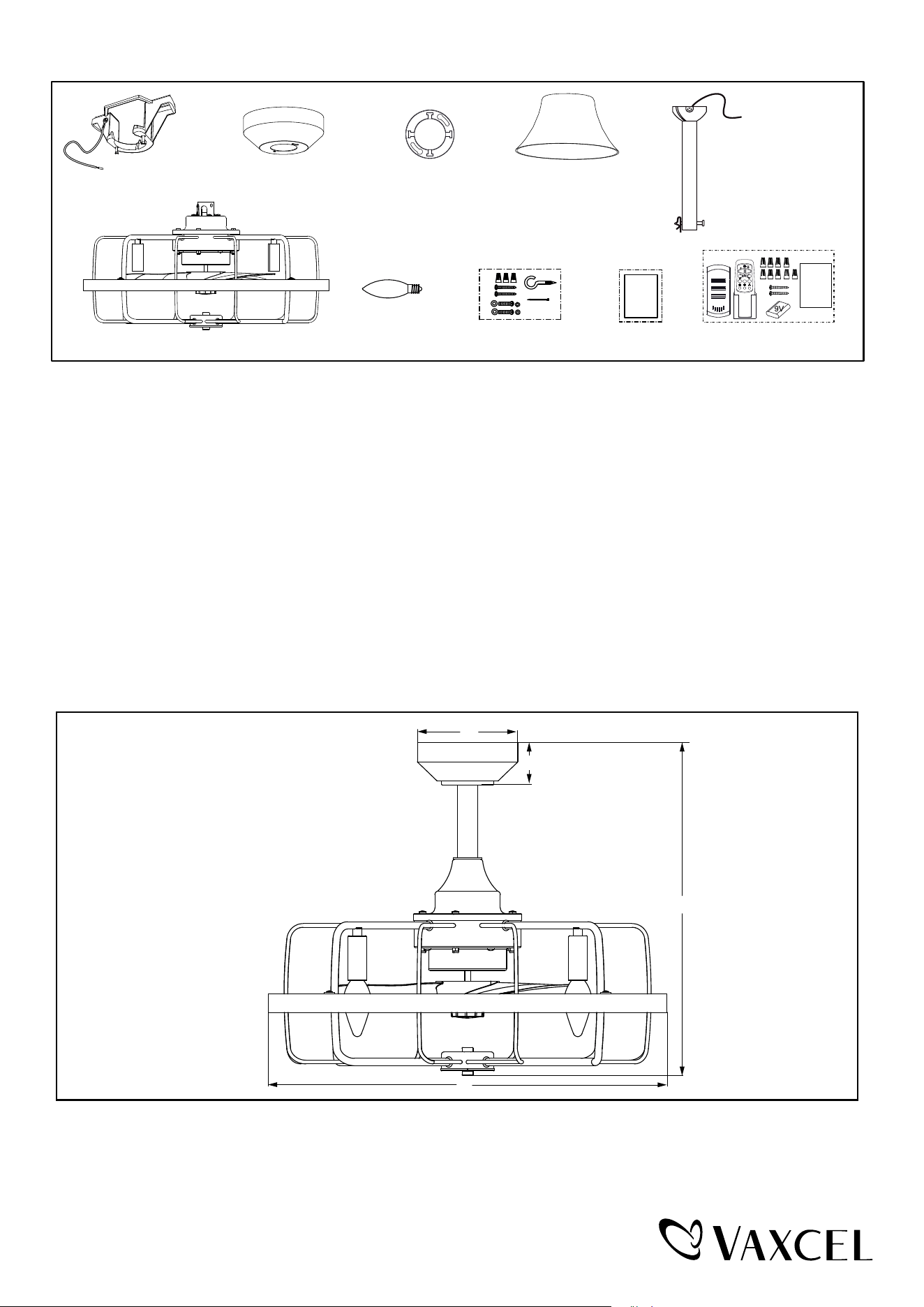
Unpack your fan and check the contents. You should have the following items.
1.) Hanger Bracket (Remove the Preassembled Hanger Bracket from the Canopy Before Installation.)
2.) Canopy
3.) Canopy Cover (Comes in a Separate Bag)
4.) Downrod Stand Cover
6.) Fan Motor Assembly
7.) 4W E12 (C) Base B11 Type LED Bulb (4 PCS)
8.) Assembly Kit
9.) Installation Instructions
10.)
Remote Control Set (Includes Receiver & Transmitter & Wire Connectors & Battery
& Screws & Remote Control Instructions)
Dimension Reference (Installed with 6" Downwrod):
5.) Downrod Set (Includes Hanger Ball, 6" Downrod, Hanger Pin & Lock Pin)
Package Contents:
1
2
4
5
6
7 8 9 10
Installation
Instructions
A. 17-3/4″ B. 21″ C. 2-1/4″ D. 5″
Remote
Control
Instructions
A
C
B
D
3
2H 4H 8H
PAGE: 2 / 10
240321
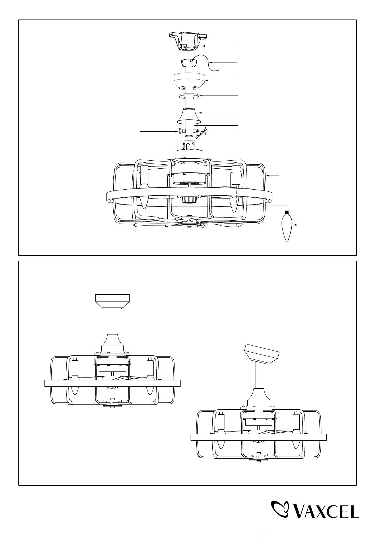
Downrod Mount
Sloped Ceiling Mount (Up to 23 degrees)
Dual Mount Drawing
Exploded View Detail
Hanger Bracket
Canopy
Hanger Ball
Canopy Cover
Downrod Stand Cover
Downrod
Lock Pin
Hang Pin
LED Bulb
Fan Motor Assembly
PAGE: 3 / 10
240321
Installation Steps :
INSTALLATION INSTRUCTIONS
IMPORTANT:
BEFORE YOU BEGIN INSTALLING THE FAN, CAREFULLY READ ALL INFORMATION N THE SEPARATE
SHEET "SAFETY INSTRUCTIONS" AS WELL AS THE FOLLOWING "INSTALLATION INSTRUCTIONS". IF IN
DOUBT, CONSULT A QUALIFIED ELECTRICIAN.
SAVE ALL INSTRUCTIONS.
NOTE: The fan weight is 14.33 lbs (6.5 kg). Be sure the outlet box you are using is securely attached to the building
structure and can support the full weight of the fan. Failure to do so can result in serious injury.
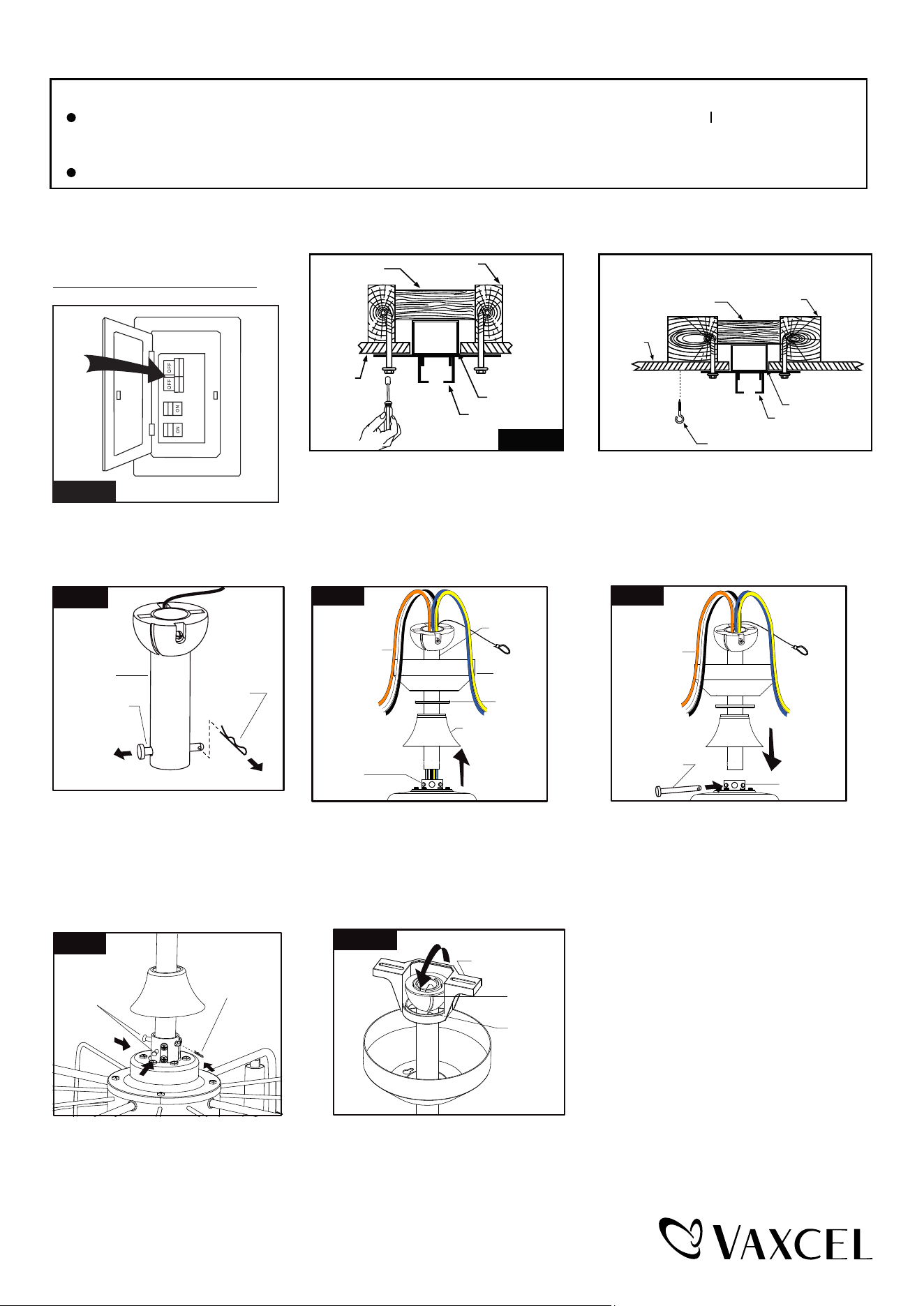
Remove the lock pin from hanger
pin and remove the hanger pin
from the downrod.
Loosen the collar screws out part way.
Insert the downrod into the collar.
Slide hanger pin through holes of
collar and downrod.
Tighten the two collar screws.
Slide lock pin into hanger pin
until it is locked into position.
Slide canopy, canopy cover (Making
sure the smooth side of canopy cover
is facing downward.) and downrod
stand cover onto downrod, as shown;
then thread motor wires through
downrod.
Hang fan on hanger bracket, and rotate the downrod until the chip on
the hanger bracket snaps into the slot on the hanger ball.
Note: For sloped ceiling installation, make sure the slot of hanger
ball and the chip of hanger bracket are toward the floor.
Slot
Chip
Hanger Bracket
Fig.7
Fig.1
Turn OFF the electric circuit at the
main fuse or circuit breaker box.
Tighten the hanger bracket to the outlet box with two mounting screws.(Make sure
the outlet box is securely installed so that it will be able to support at least the
fan weight.) Attach the safety cable hook to the ceiling and make sure the safety
cable hook is covered by the fan canopy.
WARNING: MOUNT ONLY TO AN OUTLET BOX MARKED "ACCEPTABLE FOR
FAN SUPPORT"!
Safety Cable Hook
Ceiling
Hanger Bracket
Ceiling Joist
Wood Member
(2" x 4" Approx.)
Junction Box
Fig.5.Fig.2
Ceiling
Hanger Bracket
Ceiling Joist
Wood Member
(2" x 4" Approx.)
Junction Box
Collar
Screws
Fig.6
Lock Pin
Hanger Pin
Downrod
Lock Pin
Fig.3
Fig.4
Motor Wires
Collar
Downrod
Canopy
Canopy
Cover
Downrod Stand
Cover
Hanger Pin
Collar
Fig.5
Motor Wires
PAGE: 4 / 10
240321
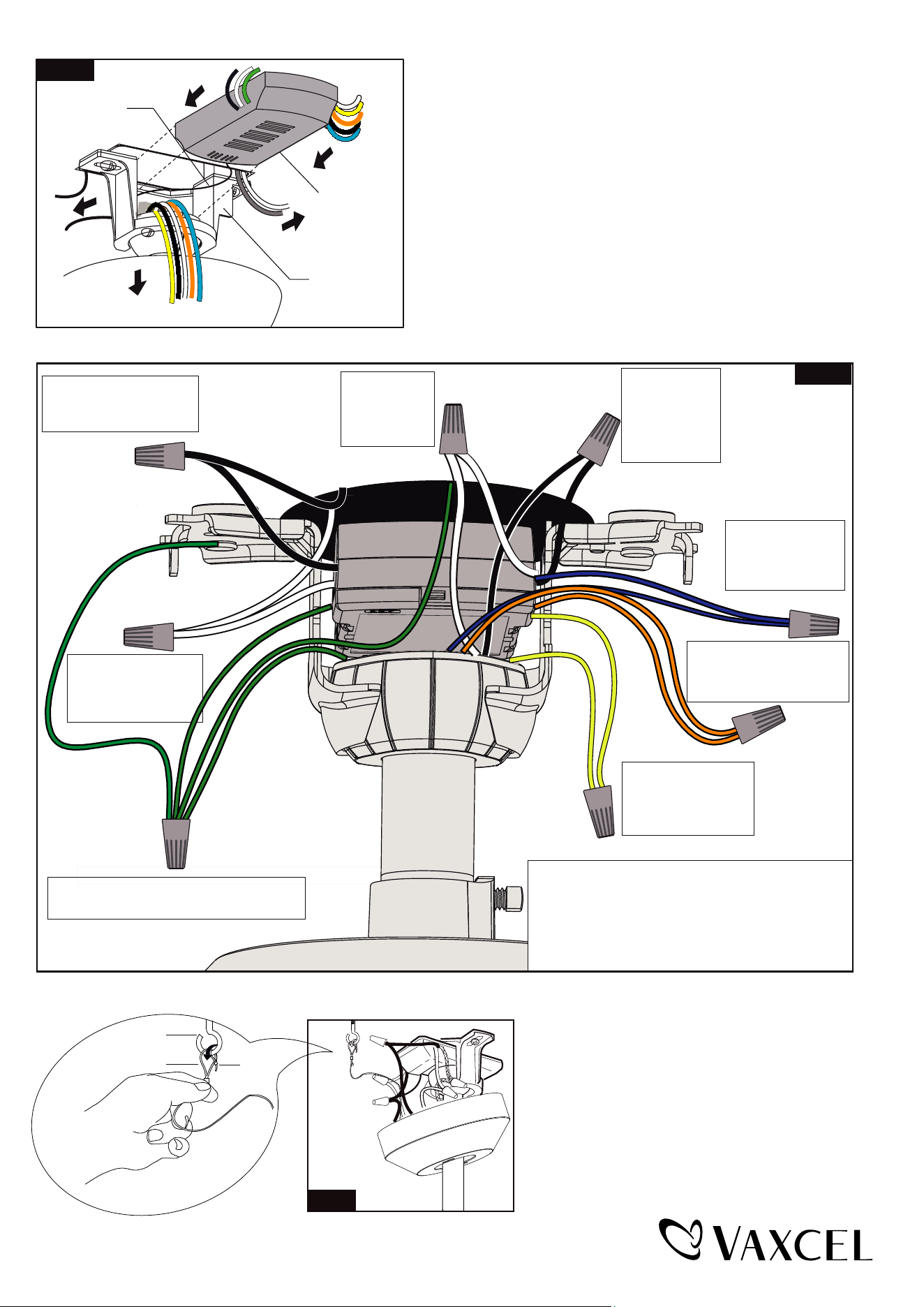
Move ground wires (a), outlet box wires (b), and motor
wires (c) away from the center of the hanger bracket as
shown. Thread the antenna through the hanger bracket
first, then thread the receiver through the hanger bracket
until it is placed in the center. Finally, cut motor wires (c) to
length needed for connections.
Fig.8
Antenna
Receiver
Hanger Bracket
a.
c.
b.
Black
Black
Black
Black
Connect the white
wire from receiver
to the white wire
from motor with a
wire connector
Connect the black
wire from receiver
to the black wire
from motor (This is
for fan control) with
a wire connector.
White
White
White
White
Connect the blue wire
from receiver to the
blue wire from motor
(This is for light control)
with a wire connector.
Connect the orange wire from
receiver to the orange wire from
motor (This is for reversible
function) with a wire connector.
Connect the yellow wire
from receiver to the yellow
wire from motor (This is
for reversible function)
with a wire connector.
Connect four ground wires (Green or bare copper)
coming from outlet box, downrod, hanging bracket
and receiver of remote control with a wire connector.
Connect the white (neutral)
wire from receiver to the
white (neutral) wire from
the outlet box with a
wire connector.
Connect the black (hot) wire
from receiver to the black (hot)
wire from outlet box with a wire
connector.
*** After making the wire connections, the wires should be spread
apart. The white (neutral) conductor from receiver and outlet
box with green (grounding) conductor on one side; the black
(hot) conductor from receiver and outlet box with the white,
black, blue, orange and yellow conductor from receiver and
motor on the other side of the outlet box.
*** The wire connection points should be turned upward and
pushed carefully up into outlet box.
Fig.9
Green
Green
Blue
Blue
Orange
Yellow
Yellow
Hang the safety cable into the safety cable hook,
tighten the safety cable to the safety cable hook
by using the zip-tie.
Fig.10
Safety Cable Hook
Safety Cable
Zip-tie
PAGE: 5 / 10
240321
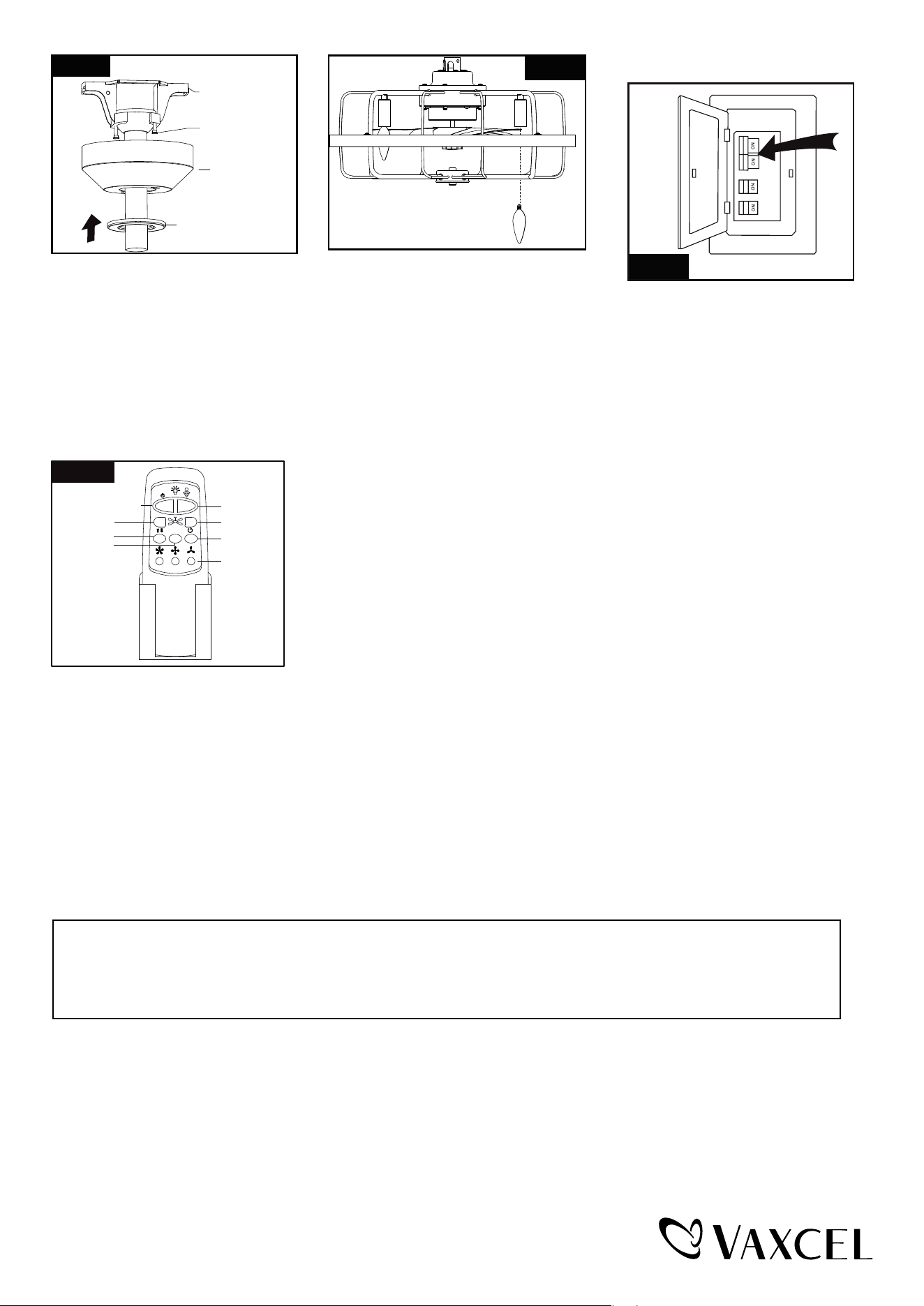
Slide the canopy up to ceiling and over
the two canopy screws on hanger bracket.
Rotate canopy clockwise, next, while
holding the canopy with one hand, slide
the canopy cover over the screws and
rotate clockwise until tight.
Note: Adjust the canopy screws as
necessary until the canopy and
canopy cover are snug.
Install LED bulbs (included). See relamping
label at socket area or packaging for
maximum wattage allowed.
NOTE: Extra light kit cannot be installed.
Turn ON the electric circuit at the
main fuse or circuit breaker box.
Fig.13
Fig.11
Canopy Screw
Hanger Bracket
Canopy
Canopy Cover
Fig.12
E12 Base Bulbs Max.40W
(4-4W E12 Base B11 Type LED
Bulbs included)
Fig.14
HI
MED
LIGHT ON/OFF
REVERSE
DIMMER
FAN OFF
LOW
TIMER
2H 4H 8H
* Press "HI" button to turn on the fan at high speed.
* Press "MED" button to turn the fan in medium speed.
* Press "LOW" button to turn the fan in low speed.
* Press "FAN OFF" button to turn off the fan.
* Press "REVERSE" button to set direction of fan rotation.
The fan speed will slow down until the fan is turned off and it will restart by spinning
in the reverse direction and resume the previously selected speed setting.
Operating transmitter:
* Press "LIGHT ON/OFF" button to turn on or turn off the light.
* Press and hold the "DIMMER" button to dim or brighten lights to the desired level and
release, and the brightness level will be memorized. Turn on the light again, then fan
light will be restored to the brightness-level at which it was dimmed last time.
* Timer Control:
Press "2H","4H" or "8H" timer button to turn off the fan and light for the selected duration.
If the light is off and the fan in on, the timer can automatically turn the fan off after the
selected timer time. (Same goes for the light.)
Press light off or fan off button to stop the timer control.
Note:
1. This remote control has a memory function setting. The fan will operate at the same speed and the fan light will
stay at the same brightness-level as the last time the power supply was turned off.
2. Compatible Wall Switches: Lutron SKU# S2-LFSQH-WH / Hunter SKU# 27183 / Legrand SKU# LSCLDC163PWCCV4.
a. The direction of fan rotation can’t be set without remote control.
b. Please use wall control to adjust the speed and the brightness-level which you need. To proceed with installation
without remote control, please start from Fig.16.
3. Compatible with E12 (C) base dimmable LED bulb: Feit Electric SKU# CTC40-827-LED-6.
Pair the remote if not connected:
Within the 10 second time frame after the main power is turned on, press and hold FAN OFF button for more than 3 seconds.
The LED light will begin to flash. Once the remote is set successfully, the fan will turn off and the light will turn on.
Note: The included transmitter was paired with the receiver at the factory with default settings, so you should not
need to pair the remote unless the connection with the fan is lost.
Install the battery (9V, included) into the transmitter.
PAGE: 6 / 10
240321
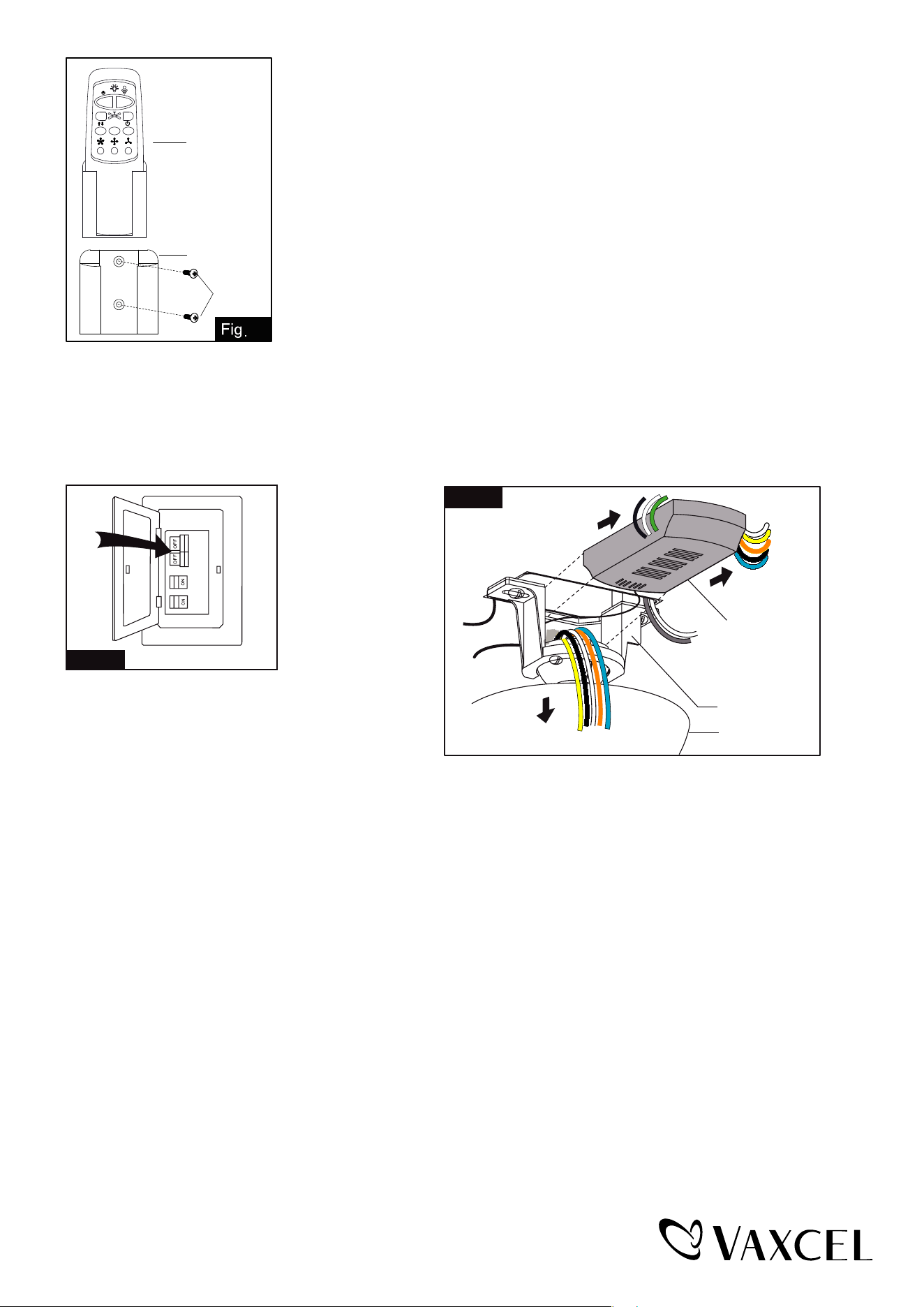
Install the transmitter wall bracket on the wall with two screws
and place transmitter in it carefully.
Transmitter
Wall Bracket
Screw
15
2H 4H 8H
Note: Remote control can not be used along with a solid-state speed control at the same time.
Install Without Remote Control
Turn OFF the electric circuit at the
main fuse or circuit breaker box. (See Fig.16)
Unscrew the canopy. Remove the wire connectors from the fan
to ceiling wire connection. The receiver should be removed from
the hanger bracket. (See Fig. 17)
Fig. 16
Fig.17
Receiver
Canopy
Hanger Bracket
PAGE: 7 / 10
240321
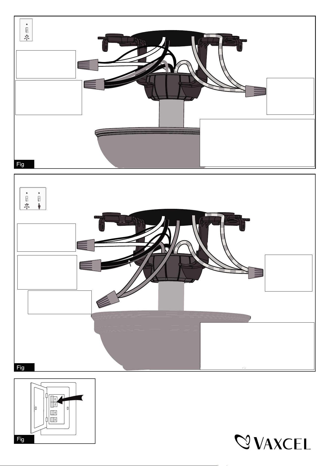
.20
Connect the white (neutral)
wire and orange reversible
wire from motor to the white
(neutral) wire from the outlet
box with a wire connector.
Connect the black (hot) wire
(This is for fan control), blue wire
(This is for light control) and
yellow reversible wire from motor
to the black (hot) wire from outlet
box with a wire connector.
Bla
Black
ck
Blue
Green
White
White
Orange
Yellow
Grounding
Green
Connect three
ground wires (Green
or bare copper) coming
from outlet box,
downrod and hanging
bracket with a wire
connector.
For a single switch
Follow these steps:
Connect three
ground wires (Green
or bare copper) coming
from outlet box,
downrod and hanging
bracket with a wire
connector.
Green
Black
Black
Blue
Green
White
Orange
Yellow
Blue
(light)
White
Grounding
Connect the black (hot) wire
(This is for fan control) and
yellow reversible wire from
motor to the black (hot) wire
from outlet box with a wire
connector.
Connect the white (neutral)
wire and orange reversible
wire from motor to the white
(neutral) wire from the outlet
box with a wire connector.
Connect the blue wire (This
is for light control) from motor
to the blue wire from outlet box
with a wire connector.
*** The wire connection points should be turned
upward and pushed carefully up into outlet box.
For dual switches
Follow these steps:
*** After making the wire connections, the wires should
be spread apart. The white (neutral) conductor from
motor and outlet box, orange conductor from motor
with green (grounding) conductor on one side; the
black (hot) and blue conductor from motor and outlet
box with the black, blue, yellow conductor from motor
on the other side of the outlet box.
*** After making the wire connections, the wires should
be spread apart. The white (neutral) conductor from
motor and outlet box, orange conductor from motor
with green (grounding) conductor on one side; the
black (hot) conductor from motor and outlet box
with the black, blue, yellow conductor from motor
on the other side of the outlet box.
*** The wire connection points should be turned upward
and pushed carefully up into outlet box.
.18
Turn ON the electric circuit at the main fuse or circuit breaker box.
.19
PAGE: 8 / 10
240321
If you have difficulty operating your new ceiling fan, it may be the result of incorrect assembly, installation
or wiring. In some cases, these installation errors may be mistaken for defects. If you experience any
faults, please check this Troubleshooting Guide. If a problem cannot be remedied or you are
experiencing difficulty in installation, please call our Customer Service Department (1-800-482-9235).
PROBLEM
1. If fan does not start:
2. If fan sounds noisy:
3. If light does not work:
4. If fan and light kit do
not work:
1. Check main and branch circuit fuses or circuit breakers.
2. Make sure that the wall control is turned "ON".
3. Check line wire connections to fan and switch wire connections in switch
housing.
CAUTION: Make sure main power is turned off.
1. Make sure all screws in motor housing are snug. (not too tight)
2. Make sure the screws which attach the fan blade bracket to the motor are tight.
3. Make sure wire connectors in switch housing are not rattling against each
other or against the interior wall of the switch housing.
CAUTION: Make sure main power is turned off before accessing switch
housing.
4. Allow "break-in" period of 24 hours. Most noises associated with a new fan will
disappear after this period.
1. Check blue wire from fan to make sure it is connected to hot wire from house.
2. Check for loose or disconnected wires in fan switch housing.
3. Check for loose or disconnected wires in light kit.
4. Check for faulty the LED light bulb.
CAUTION: Make sure main power is turned off before accessing switch
housing.
SUGGESTED REMEDY
1. Replace the battery of transmitter.
2. Re-pair the transmitter and receiver by holding the "FAN OFF" button on the
transmitter according to the manual.
PAGE: 9 / 10
240321

240321
PAGE: 10 / 10
The limited lifetime warranty covers this fan, for residential use by the original purchaser, against defects
in material or workmanship as follows:
If your fan motor fails at any time during the lifetime of the original purchaser due to defects in material or
workmanship, we will provide a replacement part free of charge.
If your fan motor fails at any time within one year after the original date of sale to the original purchaser
due to defects in material or workmanship, we will provide labor to repair the defect, with the exception
of take down/reinstallation, free of charge. The original purchaser will be responsible for all labor costs
after this one year period.
If no replacement parts are provided for any part of your fan motor that fails at any time during your
lifetime due to defects in material or workmanship, we will refund the original purchase price of your fan.
If your fan includes any integrated LED modules, the LED functionality is covered by a 5-year warranty.
If your fan blades, or any accessory, except glass globes and light bulbs, fails at any time within one year
after the original date of purchase due to a defect in material and workmanship, we will repair or replace
the defective blades, switch, or accessory free of charge, with the exception of take down/reinstallation
services.
If the original purchaser ceases to own the fan, this warranty and any implied warranty, including but not
limited to any implied warranty of merchantability or fitness for a particular purpose, become void. This
warranty and any implied warranty, including but not limited to any implied warranty of merchantability or
fitness for a particular purpose, does not cover glass globes, light bulbs, or finish on any metal portions of
the fan.
This warranty is in lieu of express warranties. The duration of any implied warranty of merchantability or
fitness for a particular purpose, with respect to any fan motor, blades, switch, or accessories, is expressly
limited to the period of the express warranty set forth above for such motor, LED modules, blades, switch,
or accessories.
This warranty excludes defects, malfunctions, or failures of any fan that are caused by repairs by persons
not authorized by us, use of parts or accessories not authorized by us, mishandling, improper installation,
modifications or damage to the fan while in your possession, or unreasonable use, including failure to
provide necessary maintenance. This warranty does not include the failure of products from extreme acts
of nature; environmental conditions not suited for the products intended use; operation in temperatures
outside of the range specified in the instruction manual; usage with improper power supply, power surges
or dips. For coastal locations, some corrosion is considered normal for the environment.
In no event shall VAXCEL be liable for consequential or incidental damages.
Some states do not allow the exclusion or limitation of consequential or incidental damages, in which case
the above limitation or exclusion may not apply. This warranty gives you specific legal rights and you may
also have other rights which vary from state to state.
Vaxcel reserves the right to repair, replace or issue a credit for any properly installed product, provided
it is returned per RMA instruction. This warranty is limited to the cost of the product only and does not
extend to transportation, installation or replacement costs.
ORIGINAL VAXCEL CEILING FAN LIMITED LIFETIME WARRANTY*
How can warranty service be obtained for your ceiling fan?
1-800-482-9235