P. 1
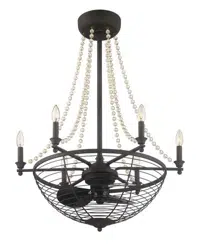
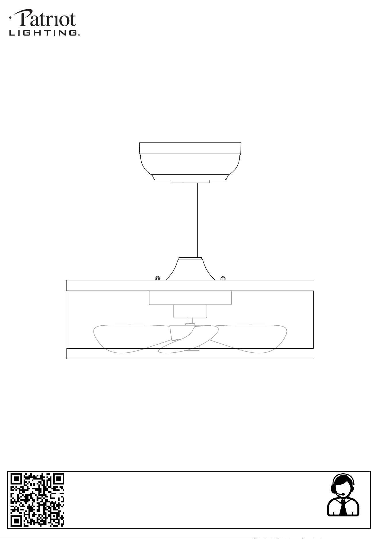
17-3/4” Verona Indoor Fandelier with 5CCT
INSTALLATION MANUAL
SKU NUMBER: 355-3700, 355-3702
MODEL: 17WHTFAN5CCT, 17BLKFAN5CCT
2025-01-16
Questions, problems, need help?
Before returning to your retailer, contact our customer service department
with the QR code:
8 a.m. - 5 p.m., EST, Monday - Friday
1-866-839-2888
Customer Service Support Site: support.ovedecors.com
P. 2
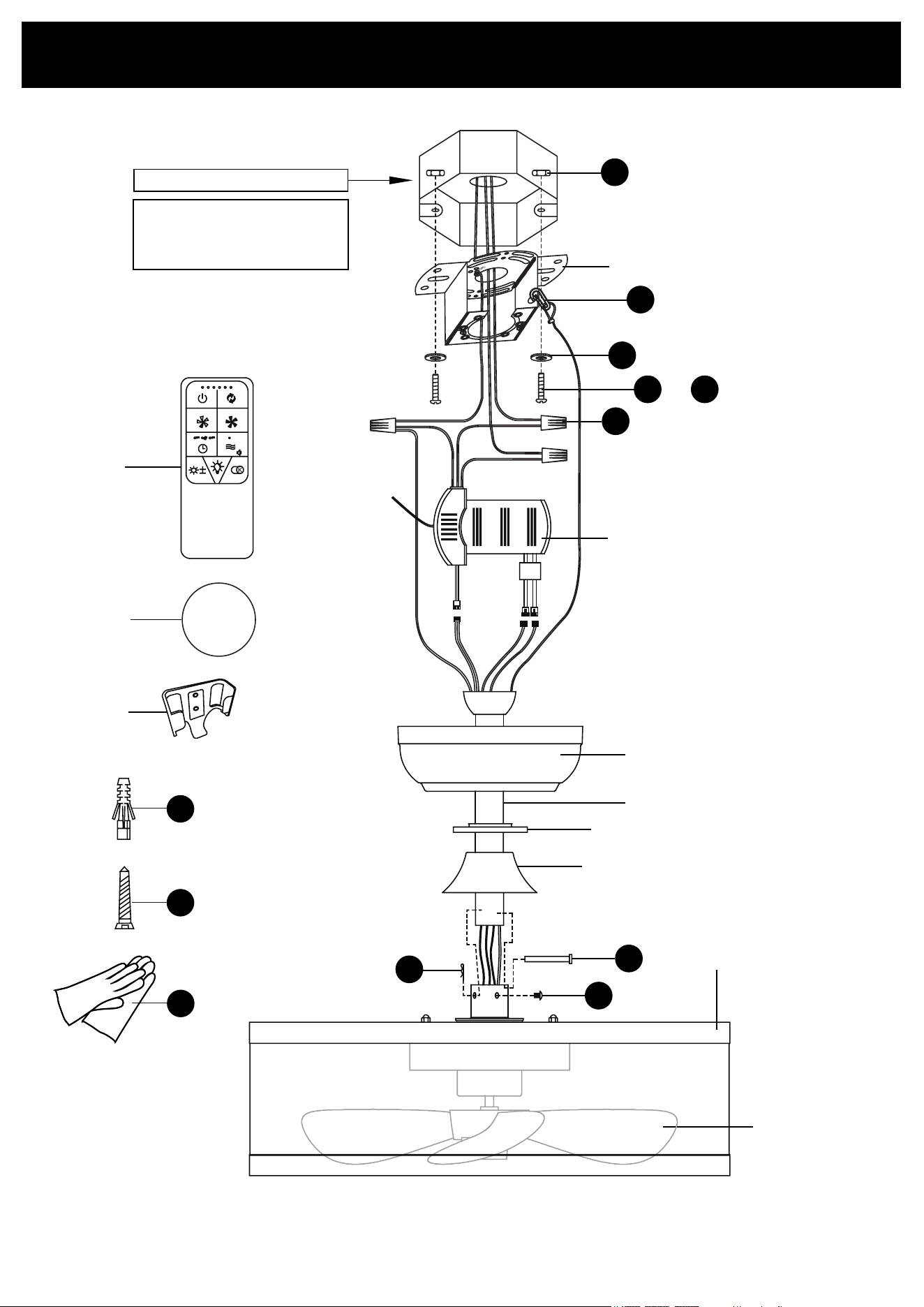
PACKAGE CONTENTS
Junction box (not supplied)
BB
EE
AA
A
B
OR
CC DD
D
F
GG
HH
FF
G
C
II
I
J
CR2032
+
E
H
K
JJ
KK
LL
WARNING
The junction box must
be ceiling fan rated.

P. 3
PARTS LIST
PART # DESCRIPTION QUANTITY REPLACEMENT PART CODE
A Mounting Plate 1 N/A
B Canopy 1 N/A
C Control box 1 N/A
D Down rod 1 N/A
E Lock nut 1 N/A
F Decorative cover 1 N/A
G Lamp 1 N/A
H Fan blade (preinstalled) 1
White: 99LHW-4X44YT5I-KY
Black: 99LHW-3OM502Z8-KY
I Remote control with holder 1 99LHW-368EE346-KY
J Battery 1 N/A
K Remote control holder 1 N/A
P. 4
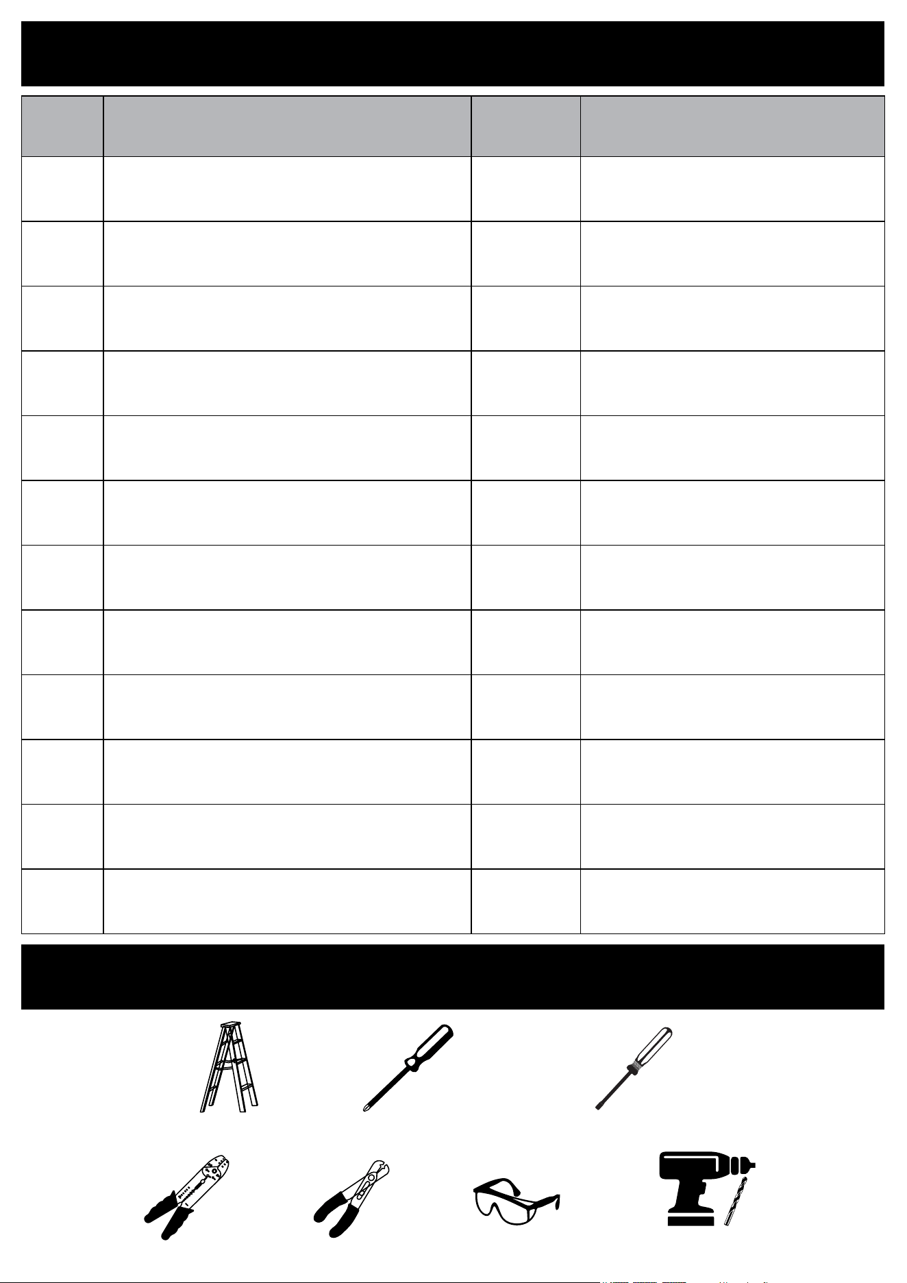
TOOLS REQUIRED (not supplied)
Ladder
Phillips Screwdriver
Safety glassesWire cutterWire stripper
Slotted Screwdriver
PARTS LIST
PART # DESCRIPTION QUANTITY CODE
AA Nut 2 N/A
BB Washer 2 N/A
CC Bolt #8x20 mm 2 N/A
DD Bolt #8x32 mm 2 N/A
EE Twist-cap Connector 3 N/A
FF Lock pin (preinstalled) 1 N/A
GG Hitch pin (preinstalled) 1 N/A
HH Screw (preinstalled) 2 N/A
II Hook 1 N/A
JJ Wall Anchor (ø6x25mm) 2 N/A
KK Screw (ST2.8x18mm) 2 N/A
LL Glove 1 pair N/A
Drill and drill bits
ø1/4” (6mm)
P. 5
SAFETY INFORMATION
Please read the following safety instructions, cautions and warning notes carefully before handling or installing this
fan/light xture to avoid injury or damage:
Power Disconnection: Turn o the circuit breaker or remove the fuse before installation or removal of any xture.
Wire Safety: Avoid damaging wire insulation during installation. Keep wires away from sharp edges to prevent
electric shock or re.
Heat Sources: Do not mount near heat sources like heaters, replaces, or candles.
Consult an Electrician: If unsure about any part of the installation, consult a qualied electrician.
Product Coverage: Do not cover the product with materials not provided, such as cloth or paper.
Part Check: Ensure all parts are present before assembly. Do not assemble if parts are missing or damaged.
Instruction Manual: Follow all provided instructions and keep this manual for future reference.
NOTICE
Any modication or alteration from what is specied in this instruction manual will void any and all warranty on this
product.
The Patriot Lighting® is not responsible for any damage to the unit or personal property caused by improper
installation. If you disregard instructional warnings, you will void your warranty and possibly deal with damage.
Consult the Patriot Lighting®’s website for any additional information or question on this product’s installation.
Power Disconnection: Before installing or removing this ceiling fan, disconnect the power by turning o the circuit
breaker or removing the fuse at the fuse box to avoid electric shock.
Blade Bracket Installation: To prevent personal injury, do not bend the blade brackets during installation, balanc-
ing, or cleaning. Do not insert foreign objects between rotating fan blades.
Speed Control: Avoid using this fan with solid-state speed control devices to reduce the risk of re or electric
shock.
Height and Clearance: Install the fan so that the blades are at least 7 feet (2.1 meters) above the oor and at
least 18 inches (0.5 meters) from the tip of the blades to the wall to reduce the risk of injury.
Support and Weight: Mount the fan to an junction box that is Ceiling Fan approved and marked “Acceptable for
Fan Support of 35 lbs (15.9 kg) or less,” using the screws provided. Ensure the junction box can support the fan’s
weight and is securely installed.
Electrical Safety: Installation must comply with the National Electrical Code (ANSI/NFPA 70) and local codes.
Ensure correct branch circuit conductor. Consult a qualied electrician if needed.
Wire Management: After making wire connections, separate the grounded and ungrounded conductors and care-
fully push the wires into the junction box. Splices should be turned upward and pushed into the box.
Product Coverage: Do not cover the product with any material not provided with the product during use.
Part Check: Before assembly, ensure all parts are present. Do not proceed if any components are missing or dam-
aged.
Additional Safety Tips:
Child Safety: Supervise children around the fan. The appliance is not intended for use by persons with reduced
physical, sensory, or mental capabilities unless supervised.
Installation Code: This product must be installed according to the applicable installation code by a person familiar
with its construction and operation.
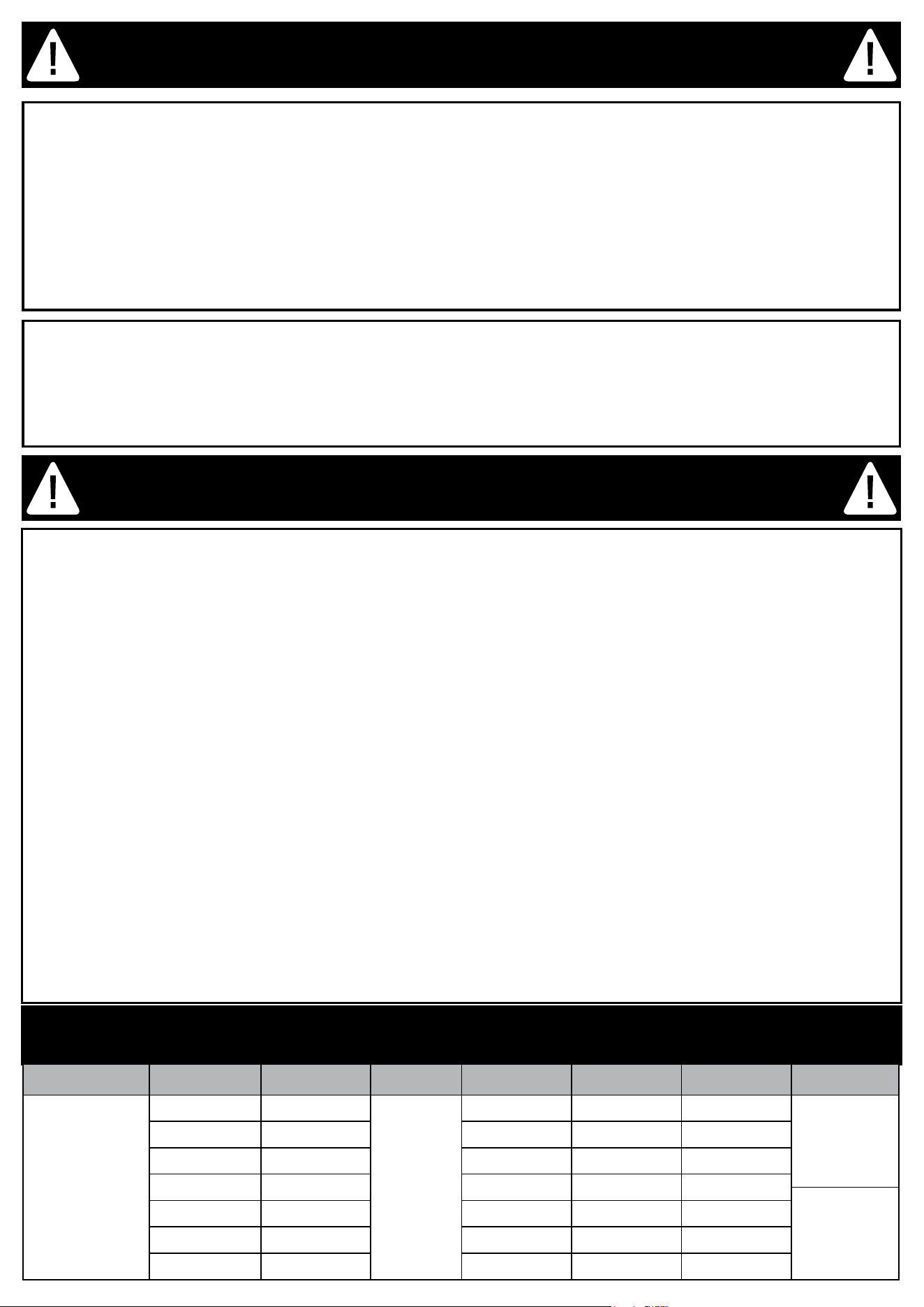
INSTALLATION WARNING
FAN SPECIFICATION
Blade Diameter Speed RPM Volt Amps Watts CFM Weight
14 in.
Standby 0
120
0.005 0.6 0
G.W.
5.5 Kg
(12 lb)
1 400 0.021 2.5 250
2 540 0.029 3.5 304
3 680 0.042 5 370
N.W.
4.1 Kg
(9 lb)
4 820 0.063 7.5 457
5 960 0.092 11 528
6 1100 0.142 17 610
P. 6
BATTERY USAGE SAFETY GUIDELINES
WARNING: KEEP BATTERIES OUT OF REACH OF CHILDREN
Ingestion Hazard:
This product contains a button cell or coin battery. Swallowing it can cause severe internal chemical burns within
as little as 2 hours and may lead to death.
If you suspect a battery has been swallowed or inserted inside the body, seek immediate medical attention.
Battery Safety:
Battery Type: CR2032, 3V.
Handling: Always purchase the correct size and grade of battery. Ensure batteries are installed correctly with
regard to polarity (+ and -).
Non-Rechargeable: Do not attempt to recharge non-rechargeable batteries. Do not force discharge, recharge,
disassemble, heat above 70°C, or incinerate. Such actions may cause injury due to venting, leakage, or explosion.
Cleaning: Clean battery contacts and those of the device before installation.
Mixing Batteries: Do not mix old and new batteries or dierent brands/types (e.g., alkaline, carbon-zinc,
rechargeable).
Disposal: Dispose of used batteries immediately and safely according to local regulations. Do not throw batteries
into a re or incinerate them. Call a local poison control center for treatment information.
Battery Compartment: Ensure the battery compartment is securely closed. If the compartment does not close
properly, stop using the product, remove the batteries, and keep them away from children.
Additional Precautions:
Safety Education: Inform others about the risks associated with button batteries and how to keep children safe.
Extended Non-Use: Remove batteries from devices not used for extended periods.
PREPARATION
Before beginning assembly, installation or operation of product, make sure all parts are present. Compare parts with
package contents list and diagram on previous page. If any part is missing or damaged, do not attempt to assemble,
install or operate the product. Contact customer service for replacement parts.
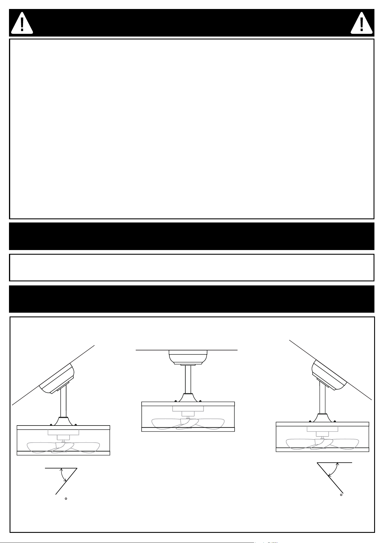
COMPATIBILITY WITH SLANTED CEILINGS
max 36
max 36
P. 7
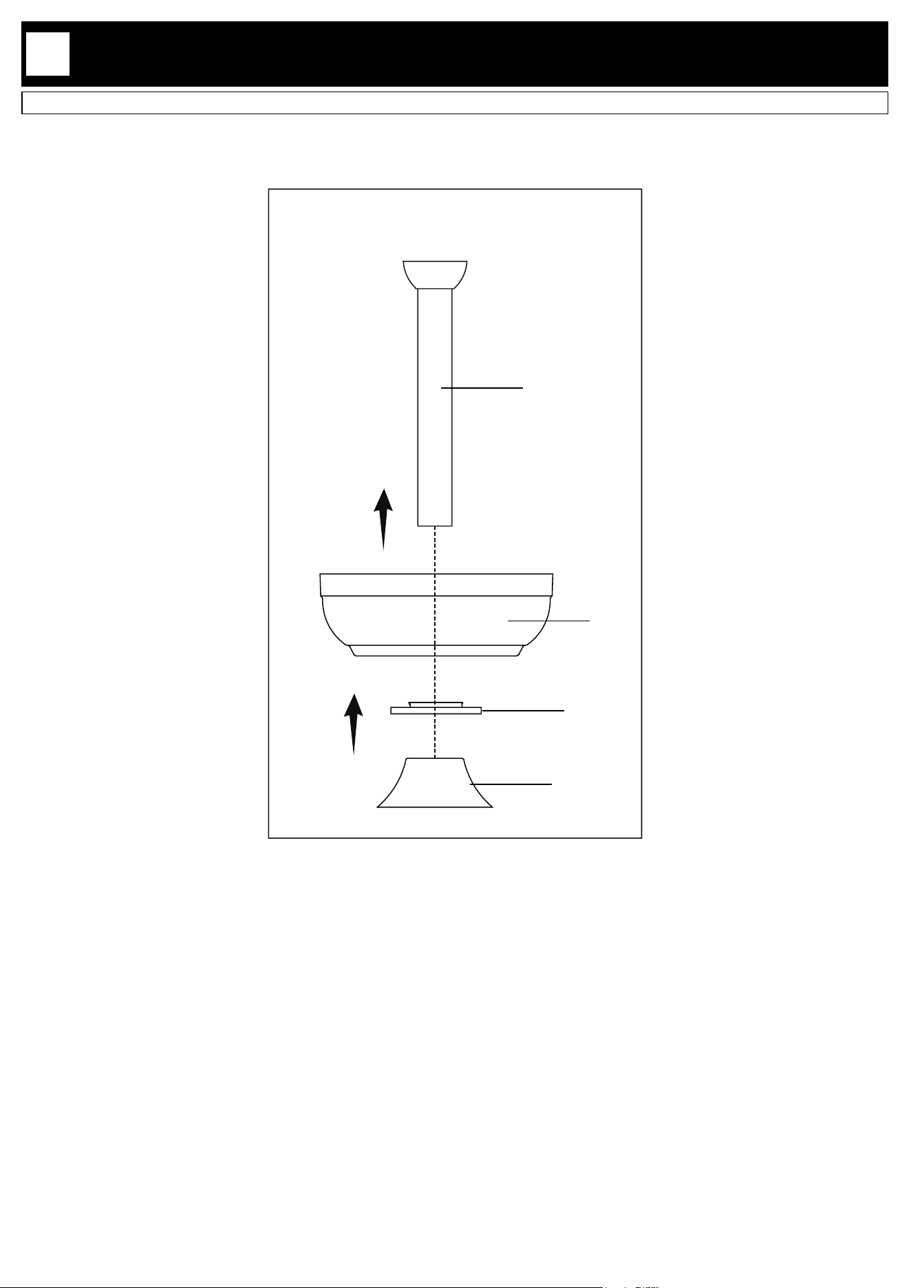
INSTALLATION
Place the canopy (B), lock nut (E) and decorative cover (F) into the down rod (D).
1
D
B
E
F
P. 8
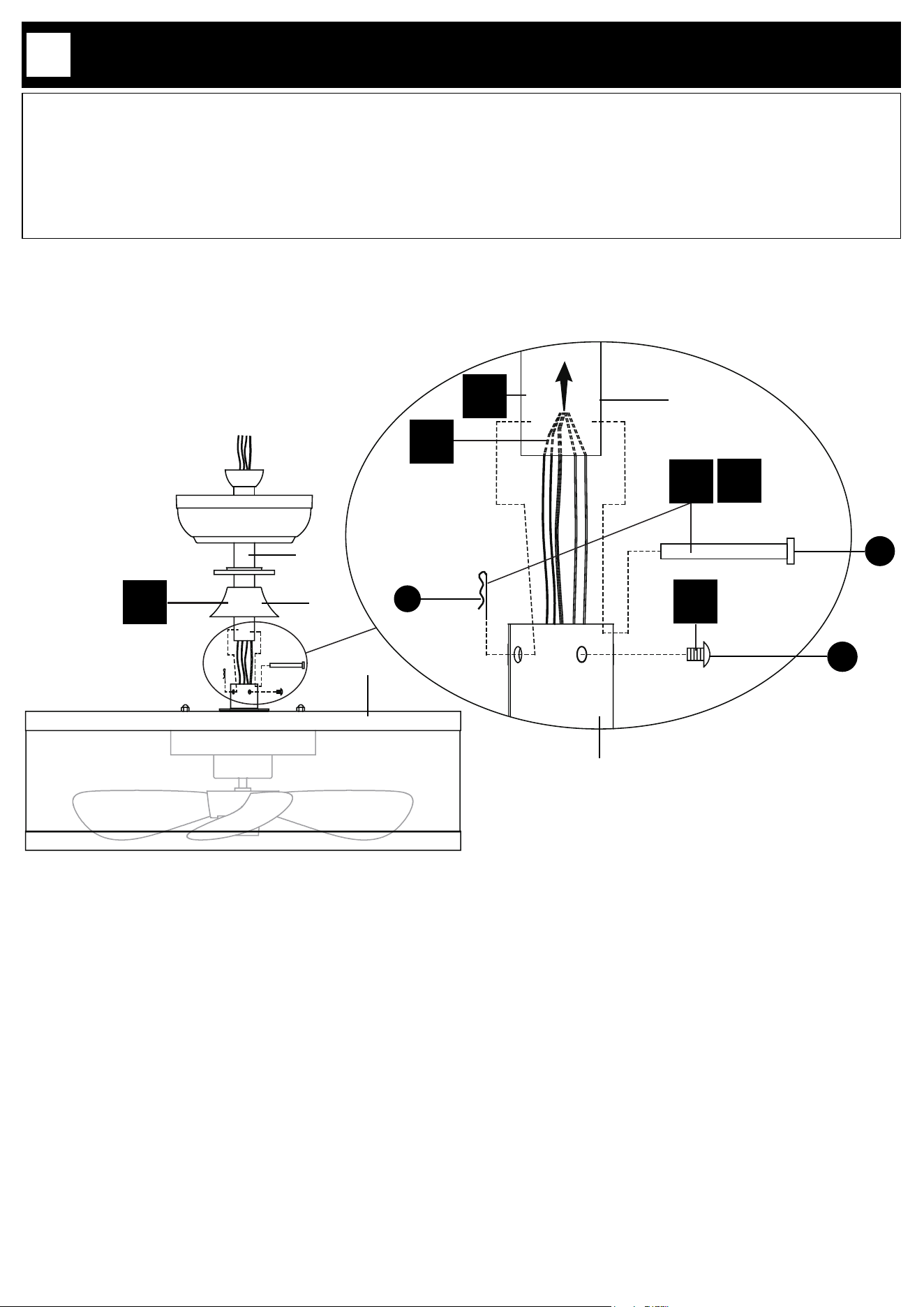
INSTALLATION
2.1. Remove the lock pin (FF) and hitch pin (GG) and loosen the screws (HH) from the lamp (G).
2.2. Thread all wires of the lamp through the down rod (D).
2.3. Insert the down rod (D) into the lamp (G).
2.4. Insert the hitch pin (GG) by aligning the holes of the down rod (D) and the lamp (G), then secure the hitch pin
(GG) by inserting the lock pin (FF) into it.
2.5. Tighten the screws (HH) into the lamp (G).
2.6. Place the decorative cover (F) onto the lamp (G).
2
2.6
F
D
2.1
HH
D
G
GG
FF
2.2
2.5
G
2.3
2.4
P. 9
INSTALLATION
3
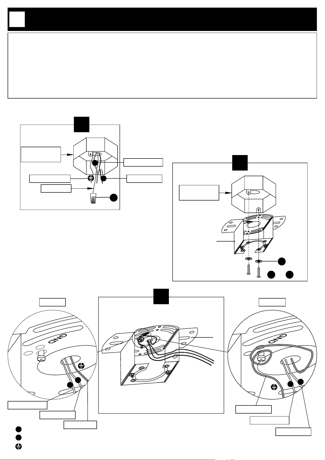
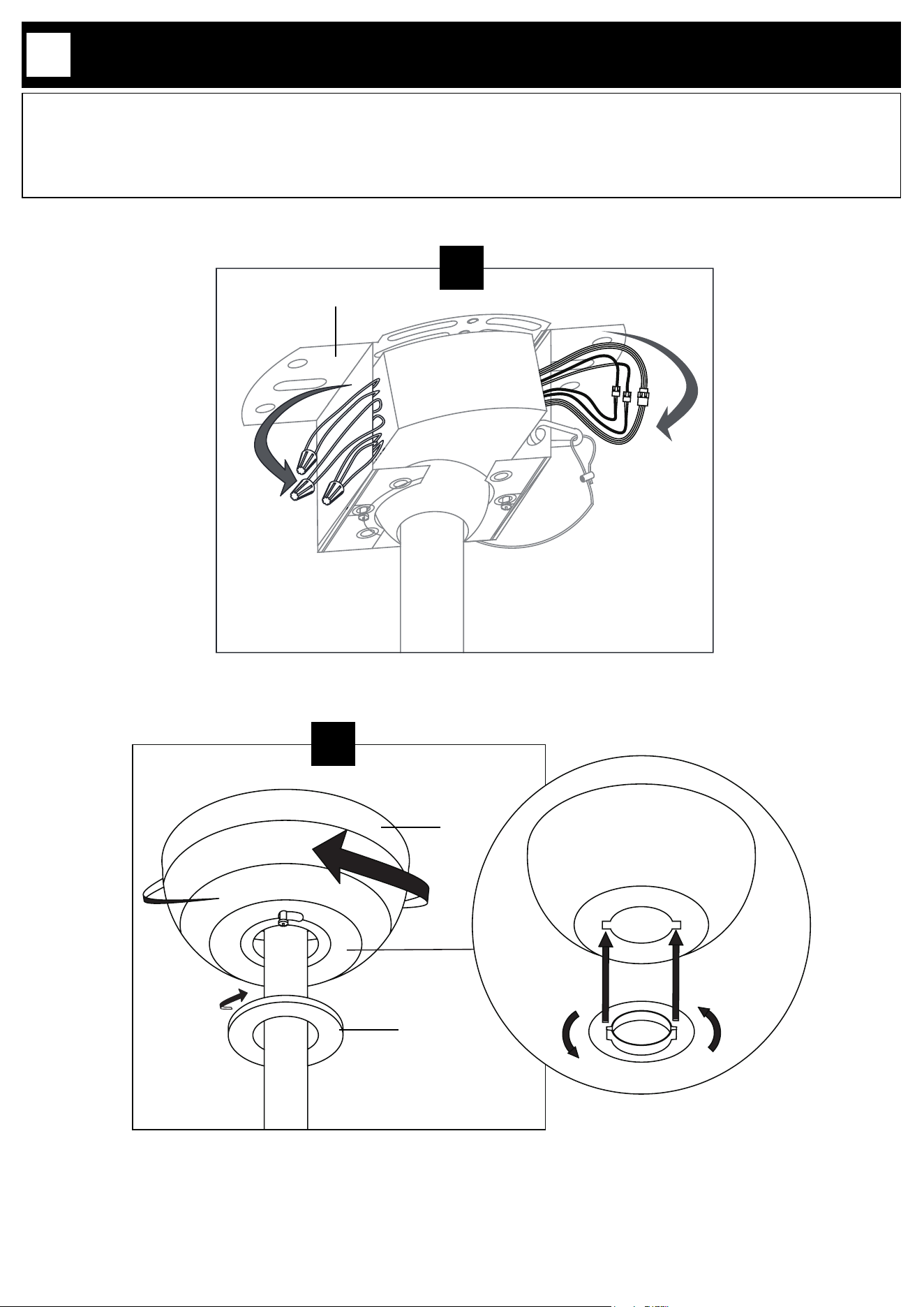
3.1.Typically, there should be three wires coming out of the junction box: the hot wire, usually black or red; the neutral
wire, typically white or gray; and the ground wire, usually green or bare (uninsulated). If there are any additional wires
beyond these three, they are not needed for installing this product. Cap them securely with twist-on wire connectors
(EE) and place them safely inside the junction box.
3.2. Securely install mounting plate (A) to junction box by tightening bolts (CC or DD) with washers (BB) onto the box.
Choose bolts (CC or DD) based on your junction box.
3.3. If the house ground wire is green (option A), pass the electrical wires of the lamp through the mounting plate (A).
If the house ground wire is copper (option B) x the copper (ground) wire from the junction box (not supplied) to the
mounting plate (A) by wrapping it around the green (grounding) bolt.
3.3
A
N
L
Option A Option B
N
L
Copper wire
Green wire
3.2
A
OR
CC DD
Junction box
(not supplied)
BB
N
L
Live
Neutral
Ground
3.1
Junction box
(not supplied)
N
L
Extra wire
EE
Black or red
White or gray
Green or bare
White or gray
Black or red
White or gray
Black or red
P. 10
INSTALLATION
4
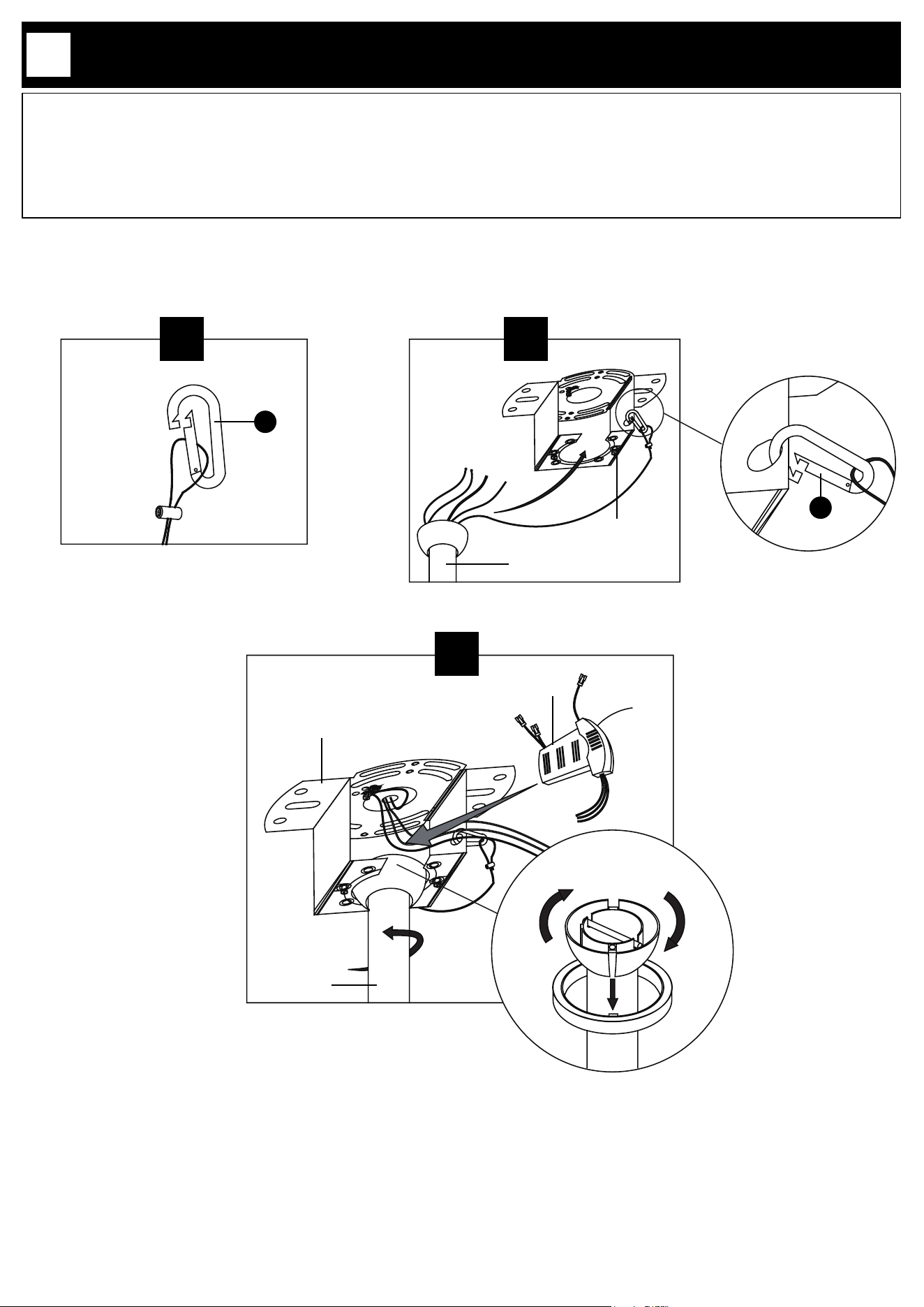
4.1. Connect the hanging wire of the lamp to the hook (II).
4.2. Connect the hook (II) onto the mounting plate (A). Place the down rod (D) into the center of the mounting plate
(A) cut-outs.
4.3. Slowly rotate the down rod (D) until the groove is locked by the mounting plate (A), make sure the tab on the
mounting plate (A) is properly seated in the groove in the down rod (D). This will help to balance the fan. Place the
control box (C) into the mounting plate (A).
4.2
D
A
4.1
D
C
A
4.3
II
II
P. 11
INSTALLATION
5
D
C
EE
5.2
A
N
L
5.1
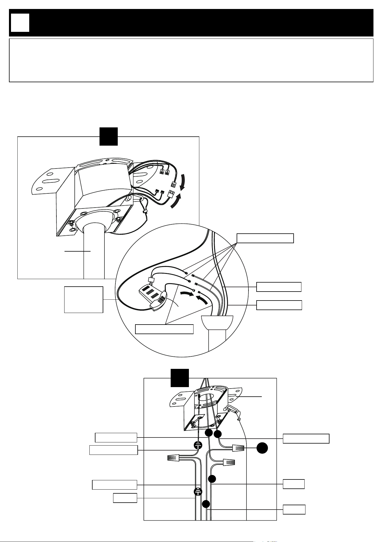
5.1. Connect the wires (white-red-yellow) of the lights to the wires from the control box (C) in the same colors.
Connect the fan control wires (red-black-yellow) of the control box (C) to the wire from the fan in the same colors.
5.2. Connect the ground wire from the junction box to ground wires from the control box (C) (green) and the light
xture (yellow-green). Connect the control box (C) neutral (white) wire to house neutral (white) wire and the control
box (C) live (black) wire to the house live (black) wire. Use provided twist cap connectors (EE) to make all connections.
C
D
White-red-yellow
Red-black-yellow
Black wire
White wire
Green wire
Hanging wire
Yellow-green
White or gray
Green or bare
Black or red
Yellow-green
Green
Black
White
L
N
P. 12
INSTALLATION
6
6.1. Organize the wires and attach them around the mounting plate (A).
6.2. Connect the canopy (B) and the mounting plate (A) by aligning the screws preinstalled on the mounting plate (A)
with the screw holes on the canopy (B). Rotate the canopy (B) and let the preinstalled screws slide into the end of
the screw holes. Tighten the screws to secure the canopy (B). Align the lock nut (E) with the canopy (B) and put the
two parts together as illustrated. Turn the lock nut (E) clockwise to rmly secure it.
6.2
E
B
B
E
6.1
A
P. 13
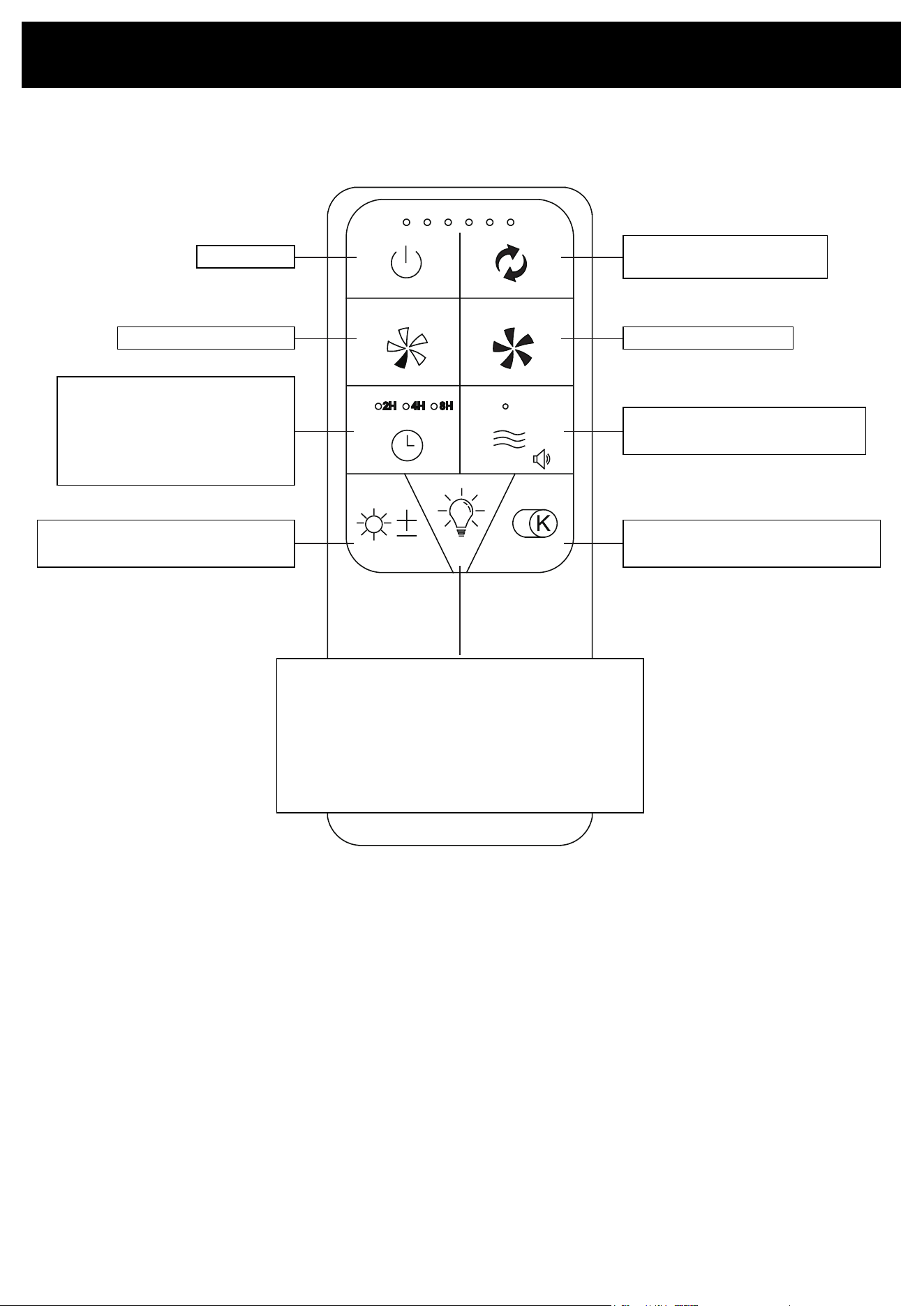
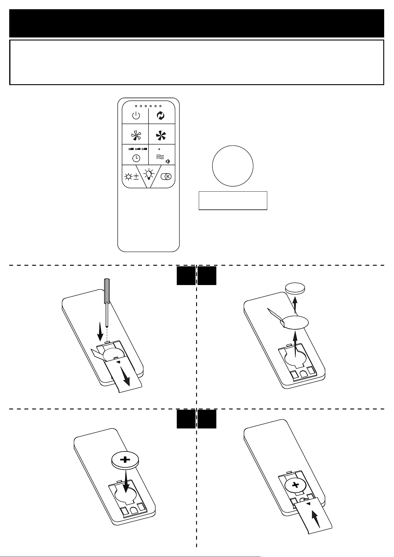
REMOTE CONTROL OVERVIEW
Fan On/O
Fan Operating Direction
(Upward/Downward)
Fan Speed Increase
Breeze
Beeping On/O (Long press)
Fan Speed Decrease
Fan Timing Control
First Press: 2H
Second Press: 4H
Third Press: 8H
Fourth Press: Cancel timing
Light Brightness
Smooth dimming (Long press)
Light Color
Smooth dimming (Long press)
* Remove the plastic lm from back of the remote before use.
* When the xture is switched on, the light display mode turns on automatically.
Press any button to turn o the display mode.
Lights On/O
First Press: Top Light ON
Second Press: Bottom Light ON
Third Press: Both Lights ON
Fourth Press: Lights OFF
Display mode (Long pressing for 5 seconds)
(Press any button to turn o display mode )
P. 14
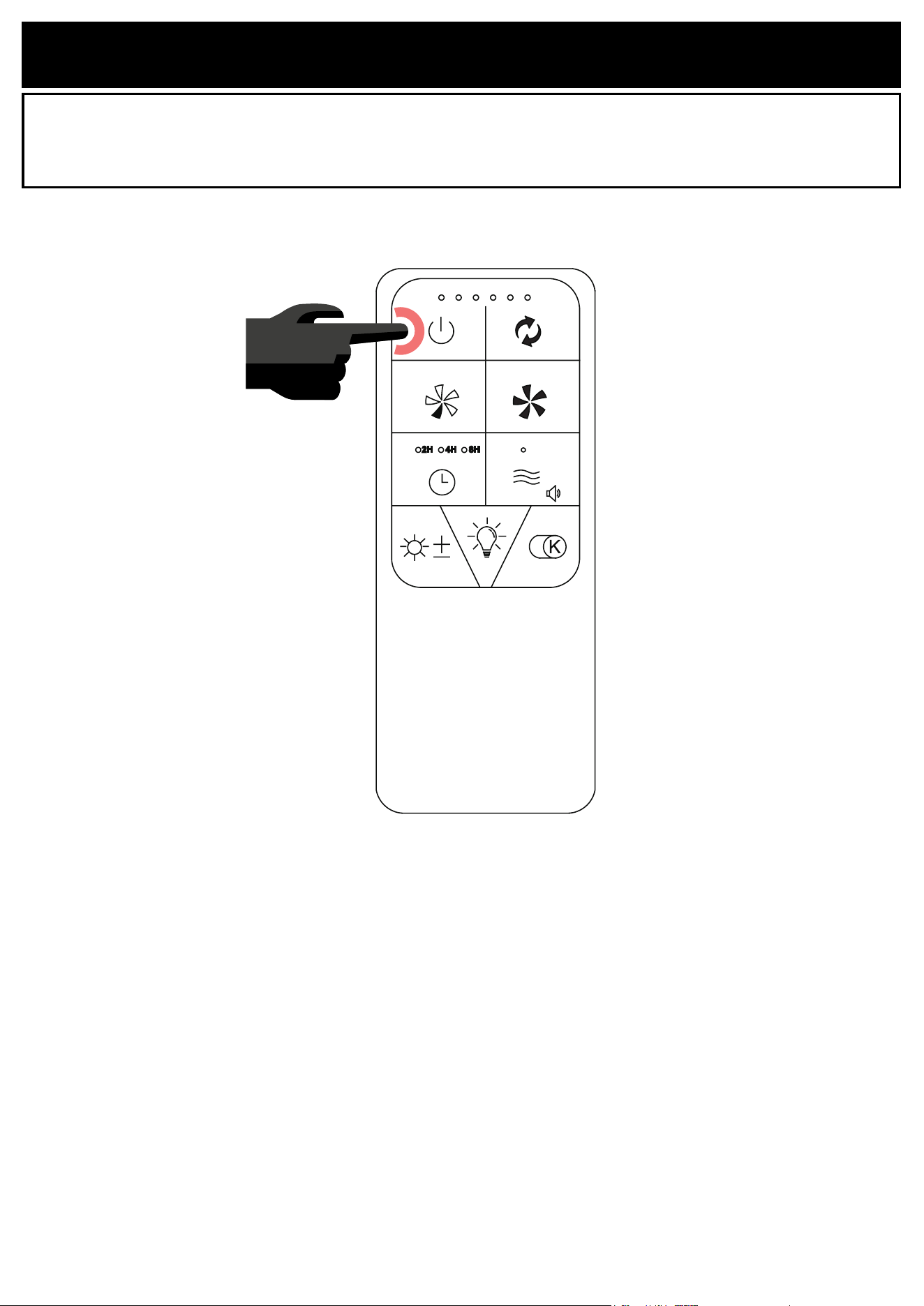
REMOTE CONTROL PAIRING
NOTICE: To ensure good function, the remote has been paired to its light.
NOTICE: The remote can be paired with multiple lights.
Turn o the light and wait at least 30 seconds, then turn on the light. Then press the FAN OFF button on the top
left of the remote control for 5 seconds. The light will emit 3 beeping sounds. The pairing is completed.
P. 15
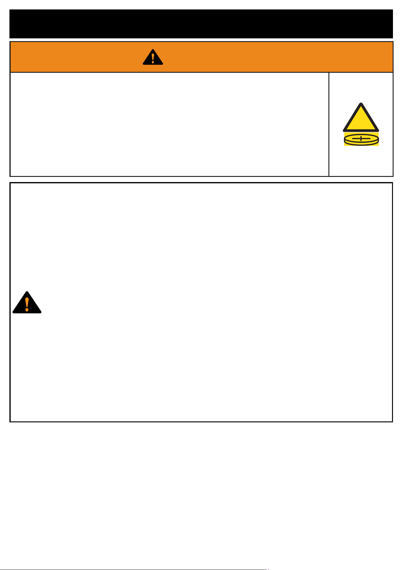
BATTERY SAFETY INFORMATION
WARNING
• INGESTION HAZARD: This product contains a button cell or coin
battery.
• DEATH or serious injury can occur if ingested.
• A swallowed button cell or coin battery can cause Internal Chemical
Burns in as little as 2 hours.
• KEEP new and used batteries OUT OF REACH of CHILDREN.
• Seek immediate medical attention if a battery is suspected to be
swallowed or inserted inside any part of the body.
!
1. Remove and immediately recycle or dispose of used batteries according
to local regulations and keep away from children. Do NOT dispose of
batteries in household trash or incinerate.
2. Even used batteries may cause severe injury or death.
3. Call a local poison control center for treatment information.
4. Compatible battery type: CR2032.
5. Nominal battery voltage: 3V
6. Non-rechargeable batteries are not to be recharged.
7. Do not force discharge, recharge, disassemble, heat above 70°C or
incinerate. Doing so may result in injury due to venting, leakage or
explosion resulting in chemical burns.
8. Ensure the batteries are installed correctly according to polarity (+ and -).
9. Do not mix old and new batteries, dierent brands or types of batteries,
such as alkaline, carbon-zinc, or rechargeable batteries.
10. Remove and immediately recycle or dispose of batteries from equipment
not used for an extended period of time according to local regulations.
11. Always completely secure the battery compartment. If the battery
compartment does not close securely, stop using the product, remove the
batteries, and keep them away from children.
P. 16
BATTERY INSTALLATION
Load the remote with one CR2032 battery. The battery compartment is located at the bottom back of the remote.
1.1. Insert screwdriver into the snap-t, then remove the battery cover by rmly sliding it downward.
1.2. Remove the battery and the insulation lm.
1.3. Put back the battery in place, as shown on the drawing.
1.4. Put back and secure the cover by sliding it in place.
CR2032 3V
Button cell battery
3V
+
1.1 1.2
1.41.3
P. 17
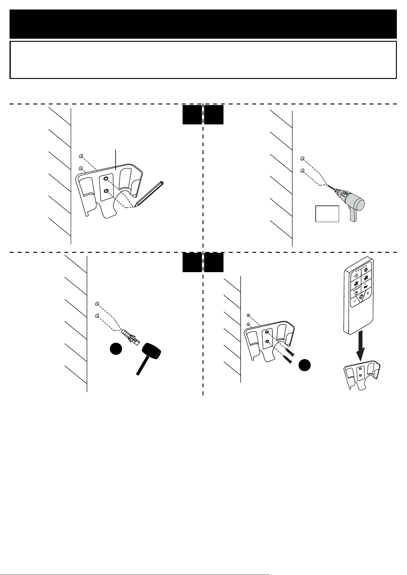
REMOTE CONTROL HOLDER INSTALLATION
1.1. Place the remote control holder (K) on wall and mark the holes positions.
1.2. Remove the holder (K) and drill pilot holes in the marked locations with a ø1/4” (6mm) drill bit.
1.3. Insert the wall anchors (JJ) using a rubber mallet until the wall anchors are ush with the wall.
1.4. Replace and secure the holder (K) with screws (KK). Do not overtighten.
1.1 1.2
1.3 1.4
ø1/16”
1.5mm
JJ
KK
K
P. 18
This device contains license-exempt transmitter(s)/receiver(s) that comply with Innovation, Science and Economic
Development Canada’s license-exempt RSS(s). Operation is subject to the following two conditions:
• This device may not cause interference.
• This device must accept any interference, including interference that may cause undesired operation of the device.
The device has been evaluated to meet general RF exposure requirement. To maintain compliance with RSS-102
- Radio Frequency (RF) Exposure guidelines, this equipment should be installed and operated with a minimum
distance of 20cm between the radiator and your body.
MAINTENANCE AND CARE
To clean the light xture, disconnect the power by turning o the circuit breaker or by removing the fuse at the
fuse box and wipe the light xture with a damp, non-abrasive cloth. Gentle reminder, do not use harsh or abrasive
cleaners as it will damage the nish of your product.
IC ID STATEMENT
CONSUMER RESPONSIBILITIES
The Patriot Lighting®’s products will remain beautiful for many years if you properly care for them.
The Patriot Lighting® does not recommend the use of harsh abrasive cleansers on any of its products. Harsh
cleansers will damage the nish of your product.
MAINTENANCE
▶ For daily maintenance, use a dry cloth.
▶ Never use abrasive cleaners or strong bleach, scrapers, metallic brushes, or other objects or any products which
can graze or tarnish surfaces.
LIMITED 5 YEAR WARRANTY
This warranty extends only to the original owner user for personal household use only. For commercial uses, additional
limitations may apply.
• The Patriot Lighting® warrants your satisfaction with each product. Should any product not meet your satisfaction
due to a visual defect, simply return it to your retailer with the original packaging, PRIOR TO INSTALLATION, for
a replacement.
• The Patriot Lighting® warrants, products to be free from defects in workmanship and materials under normal use
and service for a period of ve (5) years.
• The Patriot Lighting® will, at its election, repair, replace, or make appropriate adjustment where the Patriot
Lighting® optional inspection discloses any such defects occurring in normal usage within the warranty periods.
• Please note that the Patriot Lighting® is not responsible for installation or removal costs.
• Modication of any product’s components may void the warranty. This warranty does not cover any claim arising
from abuse, misuse, negligence, accident, improper installation or operation on the part of the purchaser. This
warranty is void if the Patriot Lighting®’s product is subject to alterations, or if repairs were done to the product.
• This warranty does not extend to any components installed by dealers, installers or by any party other than the
Patriot Lighting®.
• Implied warranties, including that of merchantability or tness for a particular purpose, are expressly limited in
duration to the duration of this warranty.
• The Patriot Lighting® disclaims any liability for special, incidental or consequential damages.
Questions, problems, need help?
Before returning to your retailer, contact our customer service department
with the QR code:
8 a.m. - 5 p.m., EST, Monday - Friday
1-866-839-2888
Customer Service Support Site: support.ovedecors.com