355-0788
LIMITED LIFETIME WARRANTY
PAGE: 1 / 6
241202
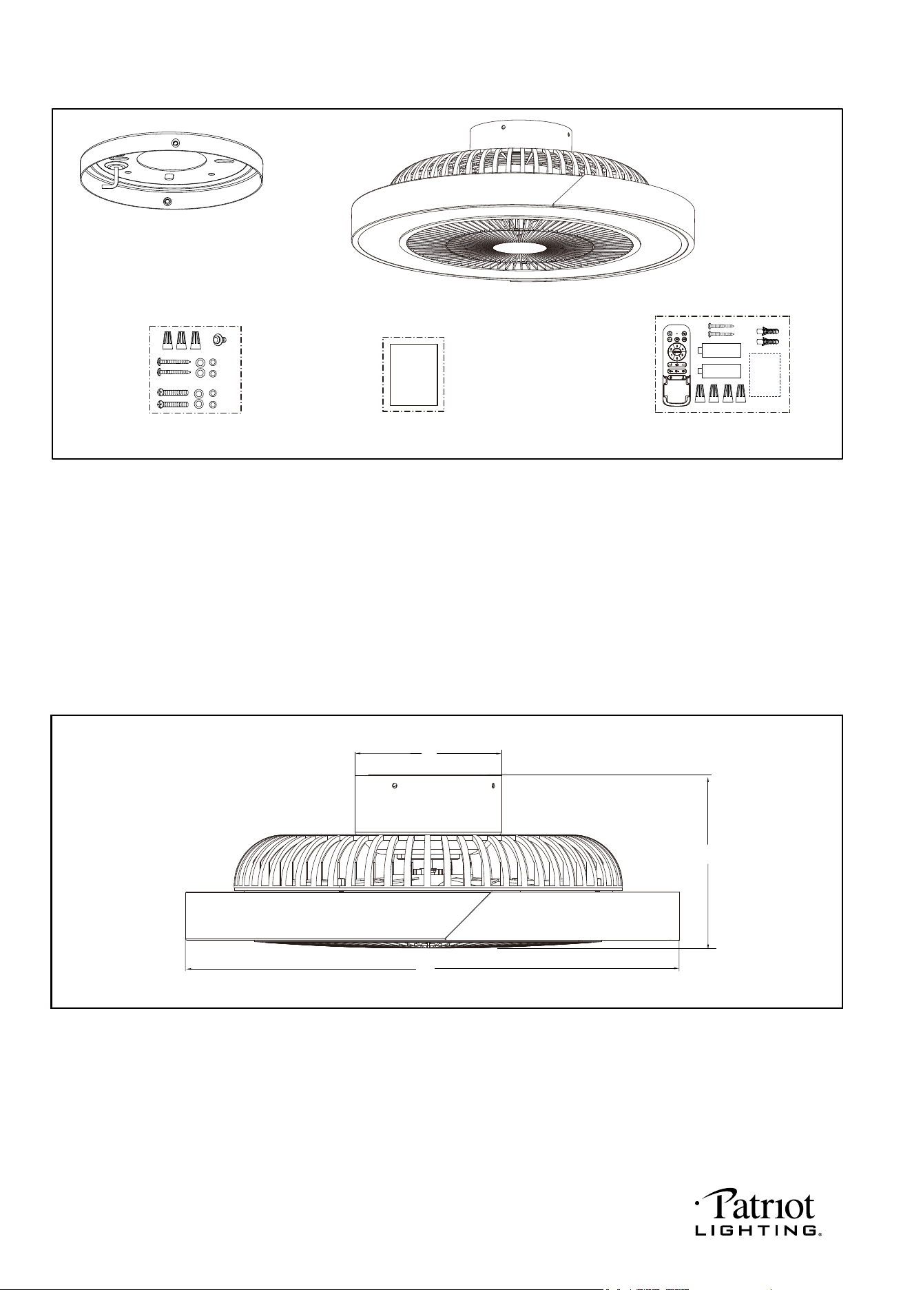
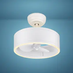
Unpack your fan and check the contents. You should have the following items.
1.) Mounting Plate
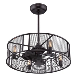
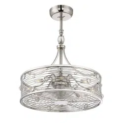
2.) Fan Assembly
3.) Assembly Kit
4.) Installation Instructions
5.) Remote Control Set (Includes Transmitter & Wire Connectors & Batteries & Screws &
Remote Control Instructions)
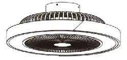
Dimension Reference:
Package Contents:
1
2
3 4
5
Installation
Instructions
A. 6-3/4" B. 6" C. 20"
Remote
Control
Instructions
1.5V
1.5V
PAGE: 2 / 6
B
C
A
241202
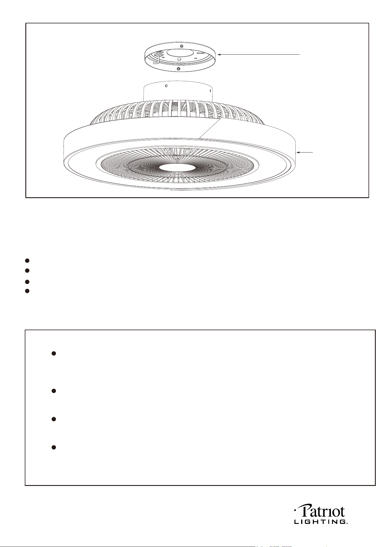
Exploded View Detail
Mounting Plate
Fan Assembly
Safety Instructions
READ ALL SAFETY INFORMATION AND INSTALLATION INSTRUCTIONS BEFORE YOU BEGIN TO
INSTALL THE FAN AND SAVE INSTRUCTIONS.
All screws of the fan must be checked and retightened where necessary before installation.
Do not insert foreign objects between rotating fan blades.
Before changing the fan direction, turn off the fan and wait for the fan blades to stop completely.
The safeguards provided by these safety instructions and by the separate installation
instructions are not meant to cover all possible conditions and situations that may occur. It must be
understood that common sense, caution and care are factors which can not be built into this product.
These factors must be supplied by the person(s) installing, caring for and operating the fan.
TO AVOID RISK OF ELECTRIC SHOCK, BE SURE TO SHUT OFF POWER AT THE MAIN
FUSE OR CIRCUIT BREAKER BOX BEFORE INSTALLING OR SERVICING THIS
FIXTURE. TURNING OFF THE ELECTRICAL POWER BY USING THE LIGHT SWITCH
IS NOT SUFFICIENT TO PREVENT ELECTRICAL SHOCK.
TO REDUCE THE RISK OF INJURY, INSTALL THE FAN SO THAT THE BLADES ARE
AT LEAST 10 FEET (3.05 METERS) ABOVE THE FLOOR AND AT LEAST 18 INCHES
(0.5 METERS) FROM THE TIP OF THE BLADES TO THE WALL.
TO REDUCE THE RISK OF FIRE, ELECTRIC SHOCK, OR PERSONAL INJURY, MOUNT
TO OUTLET BOX MARKED "ACCEPTABLE FOR FAN SUPPORT" AND USE MOUNTING
SCREWS PROVIDED WITH THE OUTLET BOX.
THE INSTALLATION HAS TO BE IN ACCORDANCE WITH THE NATIONAL ELECTRICAL
CODE, ANSI/NFPA 70-1999 AND LOCAL CODES. IF YOU ARE UNFAMILIAR WITH THE
METHODS OF INSTALLING ELECTRICAL WIRING, SEEK THE SERVICES OF A
QUALIFIED LICENSED ELECTRICIAN.
WARNING
PAGE: 3 / 6
241202
PAGE: 4 / 6
Installation Steps :
INSTALLATION INSTRUCTIONS
NOTE: The fan weight is 7.05lbs (3.2kg). Be sure the outlet box you are using is securely attached to the building
structure and can support the full weight of the fan. Failure to do so can result in serious injury.
IMPORTANT:
BEFORE YOU BEGIN INSTALLING THE FAN, CAREFULLY READ ALL INFORMATION N THE SEPARATE
SHEET "SAFETY INSTRUCTIONS" AS WELL AS THE FOLLOWING "INSTALLATION INSTRUCTIONS". IF IN
DOUBT, CONSULT A QUALIFIED ELECTRICIAN.
SAVE ALL INSTRUCTIONS.
The receiver is already fixed in the
housing.
Carefully lift the fan assembly and hang
the fan assembly on the hook of the
mounting plate by utilizing one of the
holes at the outer rim of the motor
housing so that it is securely suspended.
Then connect the wiring to your fan
according to step 5 "Making the Electrical
Connections".
Fig.1
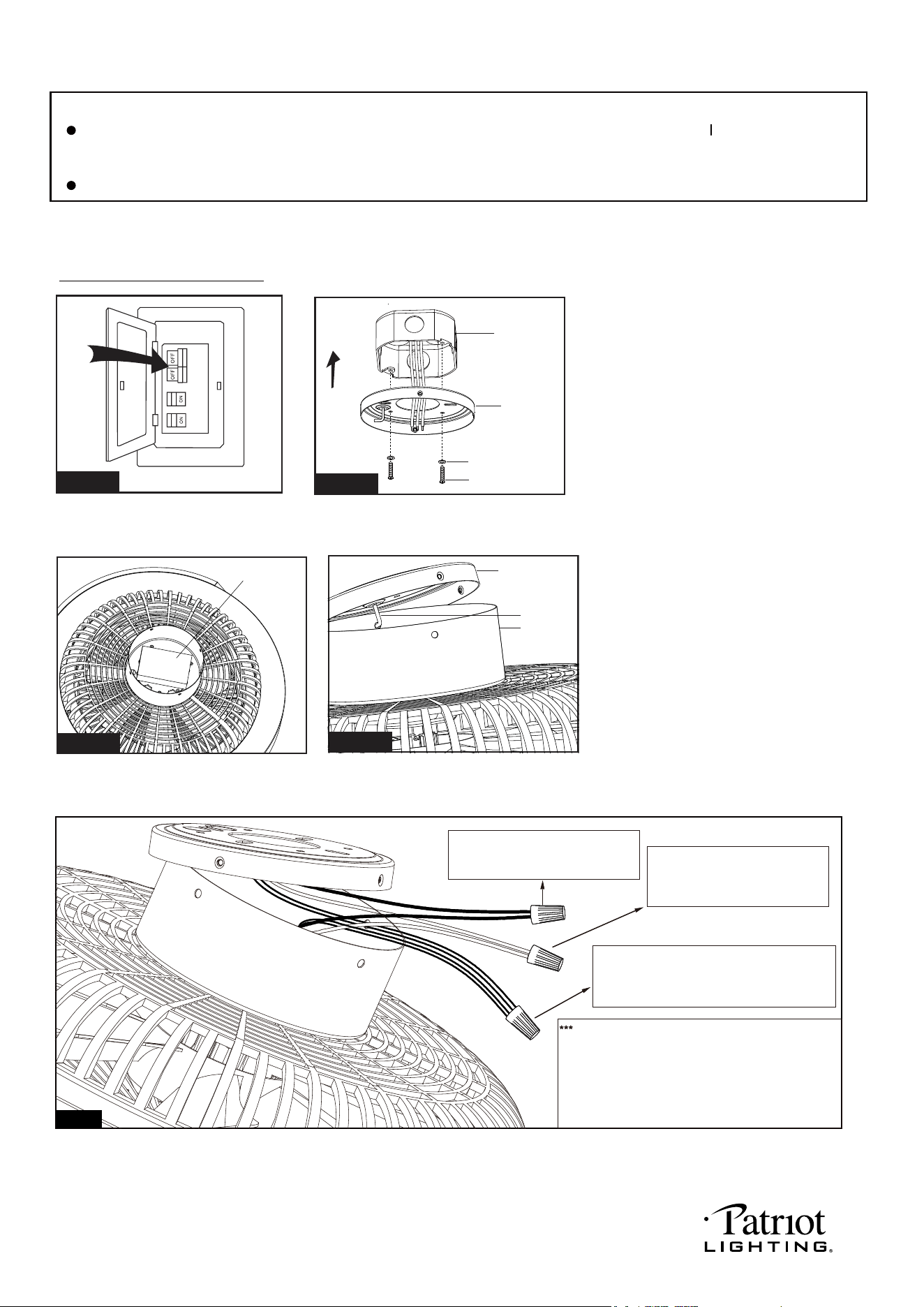
Turn OFF the electric power at the
main fuse or circuit breaker box.
Pull the wires from outlet box through the
center hole of mounting plate. Attach the
mounting plate to the outlet box, then align
and engage the bottom holes from outlet
box to the holes of mounting plate then fix
them together with washers and mounting
screws from outlet box or assembly kit bag.
WARNING: MOUNT ONLY TO AN
OUTLET BOX MARKED "ACCEPTABLE
FOR FAN SUPPORT"!
Mounting
Plate
Outlet Box
Washer
Mounting Screw
Fig.2
Receiver
Fig.3
Mounting
Plate
Fan
Assembly
Hook
Fig.4
After making the wire connections, the wires
should be spread apart. The white (neutral)
conductor and green (grounding) conductor on
one side and the black (hot) conductor on the
other side of the outlet box.
The wire connection points should be turned
upward and pushed carefully up into outlet box.
Connect the white (neutral) wire
from motor to the white (neutral)
wire from the outlet box with a
wire connector.
Connect the black (hot) wire from
motor to the black (hot) wire from
outlet box with a wire connector.
Black
Black
White
White
Ground
Ground
Connect the ground wires (Green or bare
copper) coming from the out box, mounting
plate, receiver and motor with a wire
connector.
Fig.5
241202
PAGE: 5 / 6
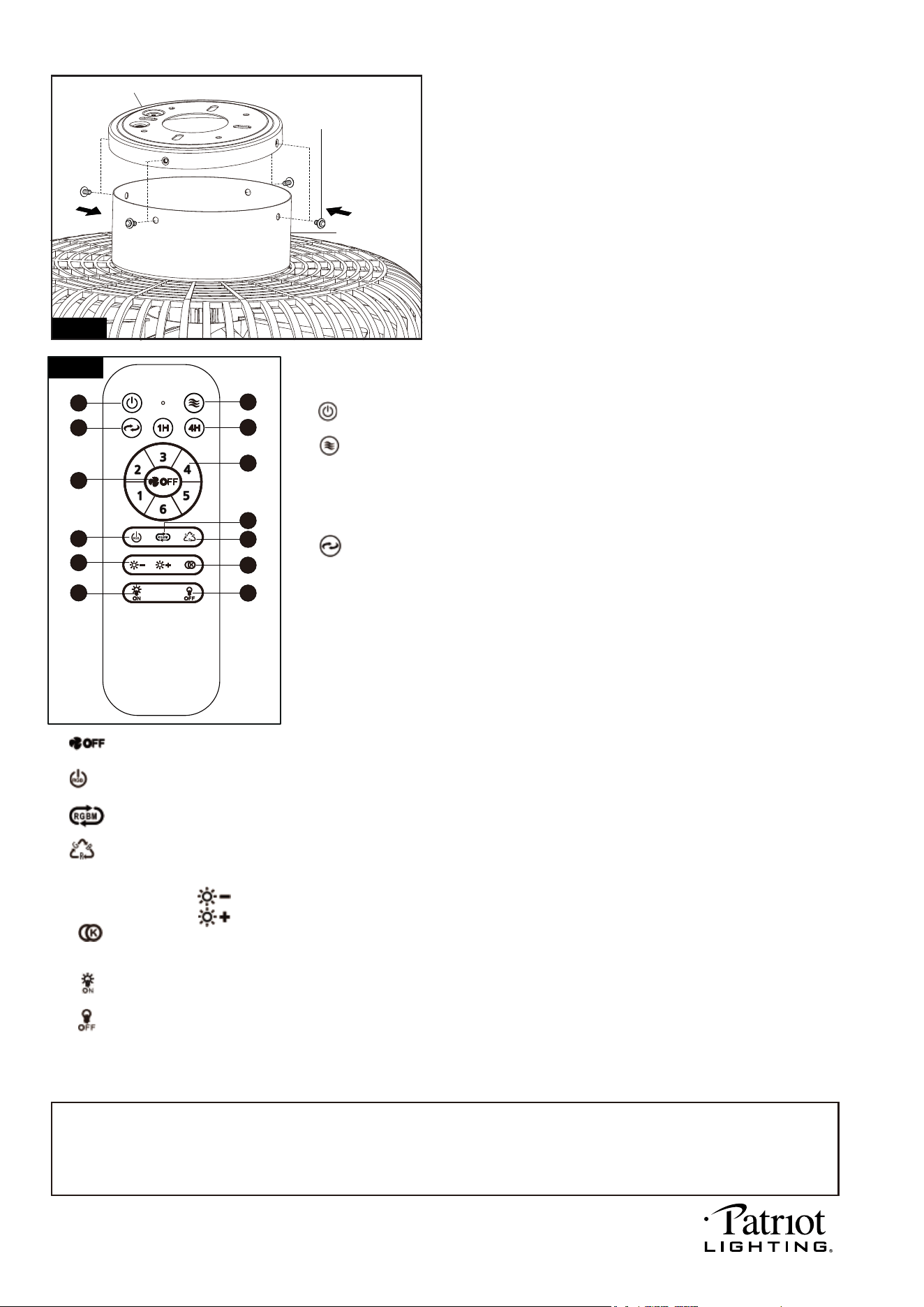
Remove four set screws from mounting plate for later use.
Then remove the fan assembly from the hook of the mounting
plate, and attach it to the mounting plate, align the four holes of
fan assembly and tighten the set screws.
Note:
This remote control has a memory function setting. The fan will operate at the same speed and the fan light will
stay at the same brightness-level as the last time the power supply was turned off.
Set the code:
Within the 10 second time frame after the main power is turned on, press and hold FAN OFF button for more than 3 seconds.
The LED light will begin to flash. Once the code is set successfully, the fan will turn off and the light will turn on.
Note: The included transmitter was paired with the receiver at the factory with default settings, so no need to set the
code again. Go through these setup steps if you found your transmitter can’t communicate with the receiver.
Set Screw
Mounting Plate
Fan Assembly
Housing
Fig. 6
Fig. 7
12
13
11
9
8
5
4
2
10
7
6
3
1
Remote control
Install two 1.5 volt batteries (type AAA, included) into the remote control.
Remote control functions:
1. " " Button:
Press this button to turn the fan and the light off.
2. " " Breese button:
Press the breeze button to cycle the fan speed. The fan will cycle through all 6 speeds in
20 seconds. If the fan is off the cycle will start at minimum "1" speed and increase until high
speed "6" is reached, then cycle slowly back down to minimum speed "1". Again, then repeat.
If the fan is on then the breeze cycle will start at that speed. To stop this function press any
other fan speed or fan off button.
3. " " Reverse button:
Press this button to control fan direction.
Please wait, as the reverse function takes time to adjust.
4. Timer Control:
Press "1H","4H" button to stop the fan speed and light after that period.
Press any other button, or turn off the electric circuit at the main fuse or circuit breaker
box can stop this function.
5. Fan speed:
1 = minimum speed 2 = low speed
3 = medium low speed 4 = medium speed
5 = medium high speed 6 = high speed
8. " " Button:
Press this button to change RGB party mode, there are a total 11 RGB party modes to choose from.
9. " " Button:
Press this button to change to a single solid RGB color. There are a total 7 colors to choose from.
10. Dimmer Function:
Press and hold the " " button to decrease brightness to the desired level.
Press and hold the " " button to increase brightness to the desired level.
11. " " button:
Press this button to change color temperature of fan light, there are a total of 5 levels of color changing from 2700K, 3000K,
3500K, 4000K to 5000K.
6. " " Button:
Press this button to turn the fan off.
7. " " Button:
Press this button to turn RGB mode off.
12. " " Button:
Press this button to turn the CCT (Correlated Color Temperature) light on.
13. " " Button:
Press this button to turn the CCT (Correlated Color Temperature) light off.
241202
PAGE: 6 / 6
Troubleshooting Guide
If you have difficulty operating your new ceiling fan, it may be the result of incorrect assembly, installation
or wiring. In some cases, these installation errors may be mistaken for defects. If you experience any
faults, please check this Troubleshooting Guide. If a problem cannot be remedied or you are
experiencing difficulty in installation, please call our Customer Service Department (1-800-887-6326).
PROBLEM
1. If fan does not start:
2. If fan sounds noisy:
3. If light does not work:
4. If fan and light kit do
not work:
1. Check main and branch circuit fuses or circuit breakers.
2. Check line wire connections to fan and switch wire connections in switch
housing.
CAUTION: Make sure main power is turned off.
3. Make sure that the wall control is turned "ON".
1. Some fan motors are sensitive to signals from Solid State variable speed
controls. DO NOT USE a Solid State variable speed control.
2. Allow "break-in" period of 24 hours. Most noises associated with a new fan will
disappear after this period.
1. Check black wire from fan to make sure it is connected to hot wire from house.
2. Check for loose or disconnected wires in fan switch housing.
3. Check for loose or disconnected wires in light kit.
4. Check for faulty the LED module.
CAUTION: Make sure main power is turned off before accessing switch
housing.
SUGGESTED REMEDY
1. Replace the battery of transmitter.
2. Re-pair the transmitter and receiver by holding the "FAN OFF" button on the
transmitter according to the manual.
241202
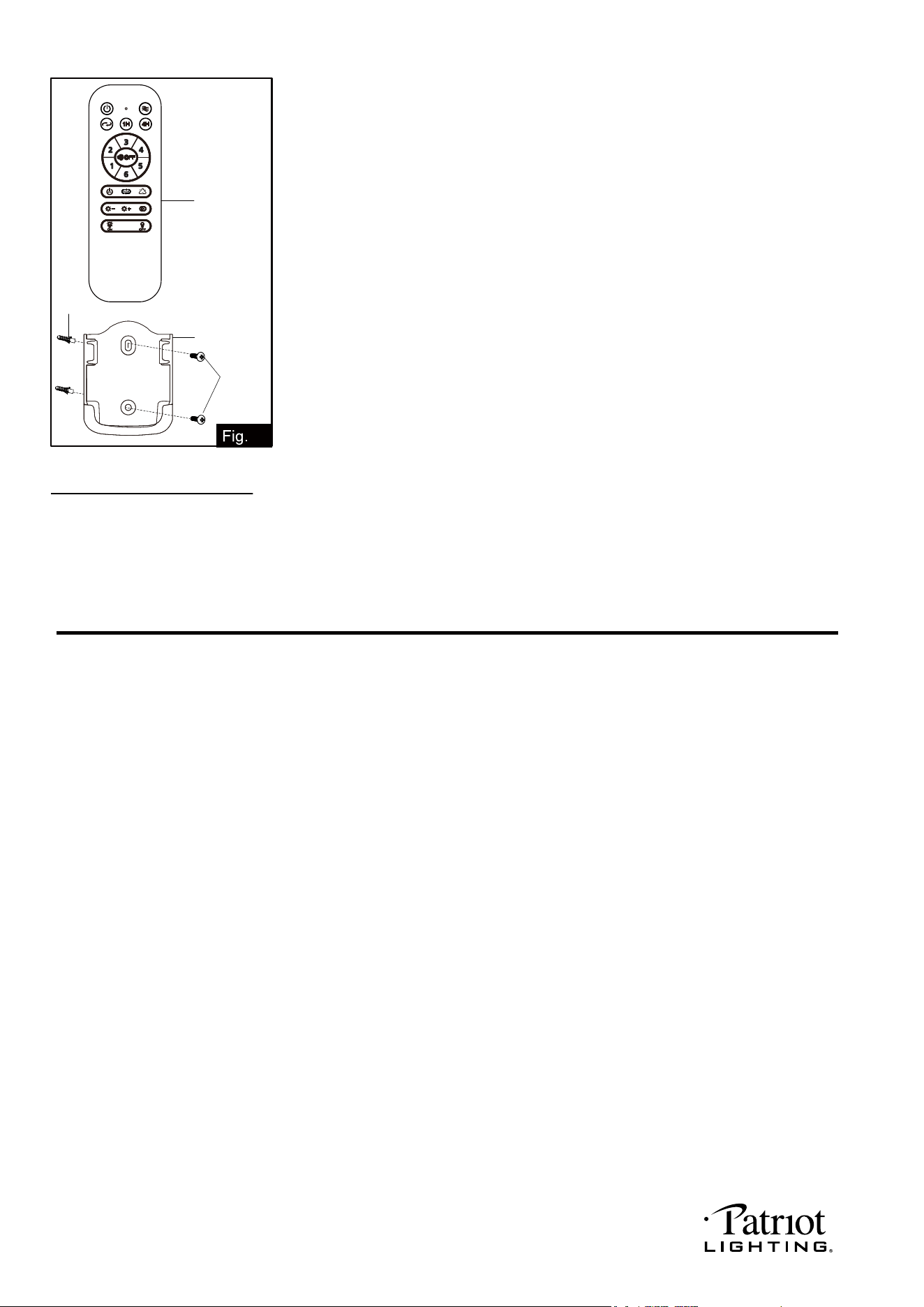
Install the transmitter wall bracket on the wall with two anchors and two screws
and place transmitter in it carefully.
Transmitter
Wall Bracket
Screw
8
Anchor