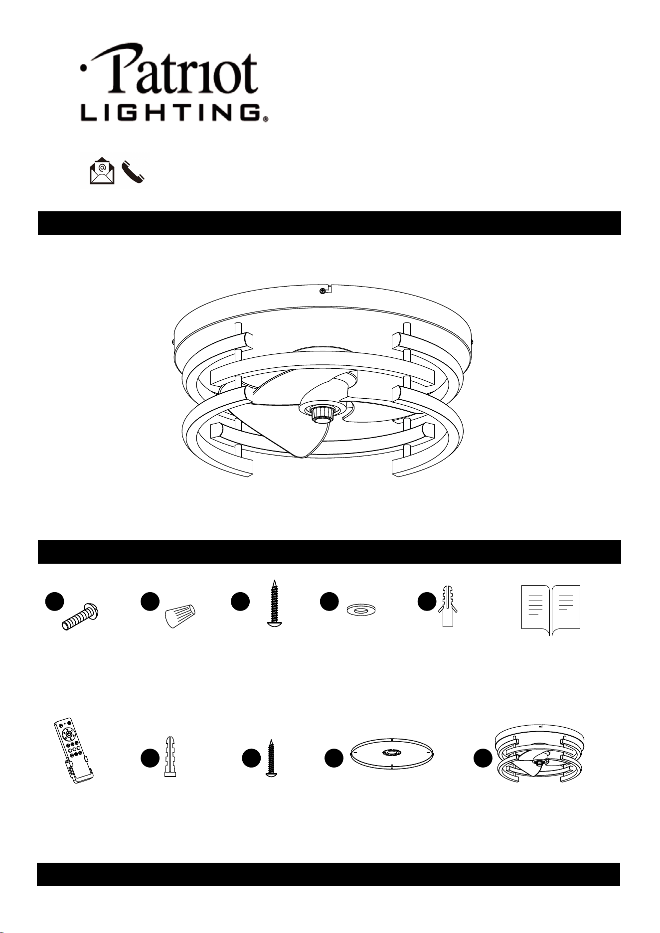
PACKAGE CONTENTS
CONTENTS
X 2 X 3
Anchor (big)
x 6
Flat Washer
x 8
(Spare parts 2pcs)
(Spare parts 2pcs)
X2
Transmitter
X1
Installation Instruction
X1
X2
Fan Body
X1
Mounting Plate
(Preassembled)
X1
AA
Outlet box Screw
A
Anchor (small)
B
Tapping Screw (small)
C D
BB
Wire Connector
x 6
CC
Tapping Screw (big)
(Spare parts 2pcs)
DD EE
Questions, problems, missing parts?
Please email us at [email protected]
or call us at 1-888-722-5089.
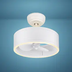
SKU Number: 355-3302
Model Number: CF81076
16-7/8" Indoor Flush Mount Ceiling Fan
1
(Note:Havdware shown not in actual size not shown in actual size)
SAFETY INFORMATION
WARNING: To reduce the risk of electrical shock or fire, do not use this fan with any solid-state fan speed control
device. It will permanently damage the electronic circuitry.
WARNING: To reduce the risk of personal injury, do not bend the blade arms (also referred to as flanges), when
installing the brackets, balancing the blades or cleaning the fan.
WARNING: Do not insert foreign objects in between rotating fan blades.
WARNING: To reduce the risk of fire, electric shock or personal injury, mount the fan to the outlet box marked
acceptable for fan support with the screws provided with the outlet box.
2
.
Do not insert foreign objects in between rotating fan blades.
The fan weight is 8.4Ib (3.8kgs). Be sure the outel box (not inc luded) is securely attached to the building
structure and is marked "Acceptable For Fan Support" . Failure to do so can result inserious injury.
All sets crews of the fan must be checked and retightened where necessary before installation.
Before changing the fan direction, turn off the fan and wait for the fan blades to stop completely.
The safeguards provided by these safety instructions and by the separate installation instructions are not meant to
cover all possible conditions and situations that may occur. It must be understood that common sense, caution and
care are factors which cannot be built into this product.These factors must be supplied by the person(s) installing,
caring for, and operating the fan.
Hanging Board release
3
PREPARATION
To avoid damaging the product, assemble it on a soft, non-abrasive surface, such as carpet or
cardboard. Inspect each part for defects such as the wire insulation for any cuts, abrasions, or
exposed copper that may have occurred during shipping. If there is a defect in the wire, do not
continue the assembly process.
Estimated Assembly Time: 5-20 minutes
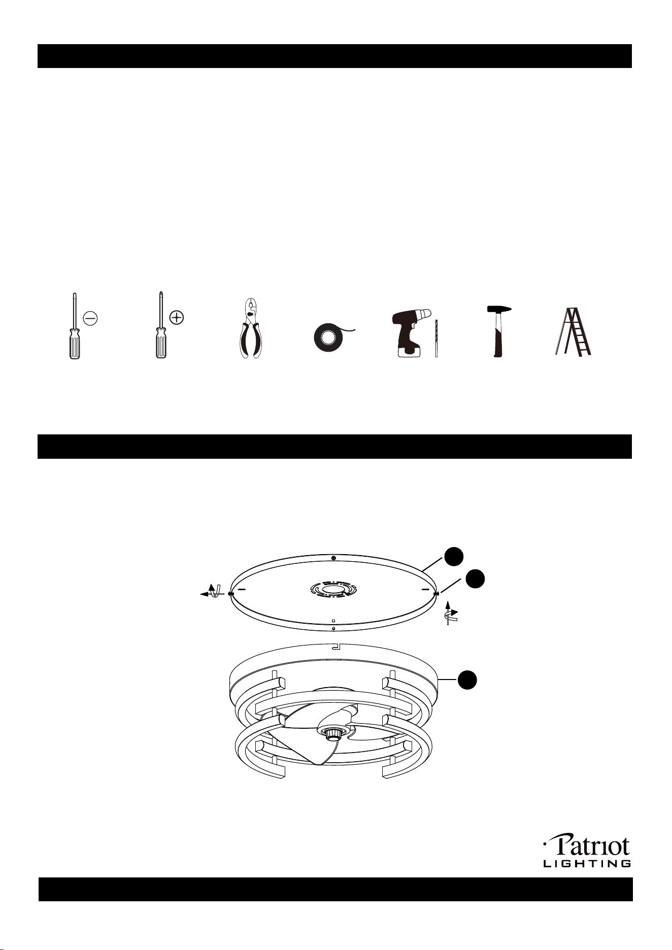
TOOLS REQUIRED
Electrical tape
Flathead
screwdriver
Phillips
screwdriver
Wire cutter
Step ladder
power drill
hammer
Detach the mounting plate (C) from the fan body (D) by loosen the mounting screws (FF), and still keep the
screws (FF) on the mounting plate (C) for easy handling later on.
PRE-INSTALLATION
C
D
FF
lock the mounting plate (C).
3. Hang the wire rope on the mounting plate (C).
4.
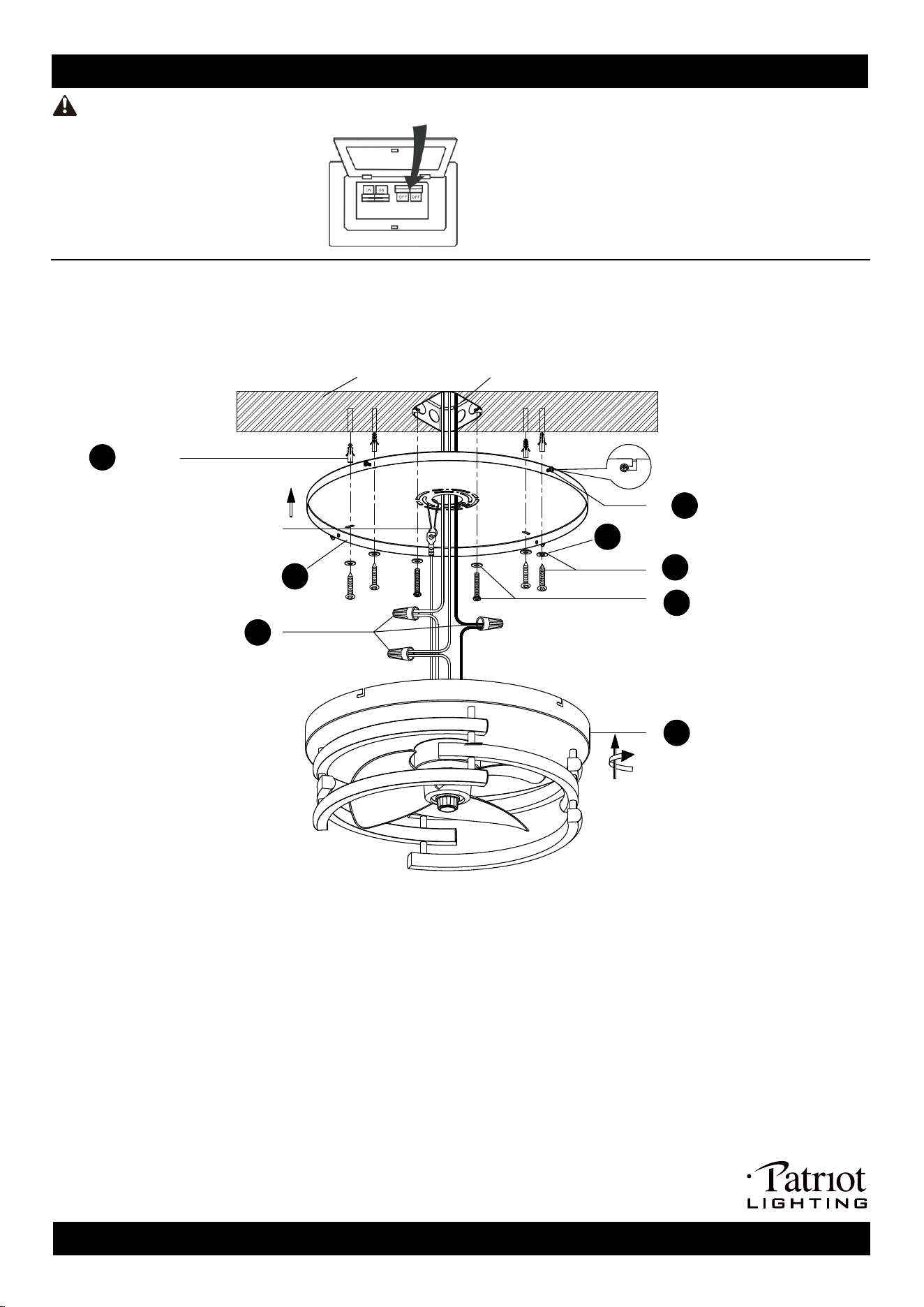
1. Fix the mounting plate (C) to the outlet box with the outel box screws (AA) and flat washer (DD).
2. Fix the mounting plate to the wooden ceiling using big tapping screws (CC) and flat washers (DD). NOTE: If the
ceiling is concrete, before fix the mounting plate (C) to the outlet box, drill a hole of 6MM with a power drill, push
the big anchor (EE) into the hole with a hammer,and then use big tapping screws (CC) and flat washers (DD) to
Pull out the source wires from the outlet box. Make wire connections using wire Connector (BB) as follows:
ASSEMBLY INSTRUCTIONS
4
WARNING:
Turn off the power at fuse or circuit box.
DANGER: Failure to disconnect the power supply prior to installation may result in serious injury
or death.
N(White)
outlet box
(not included)
Ground wire
L(Black)
(For concrete ceilings only)
3
Ceiling
2
CC
1
AA
DD
5
D
BB
4
C
EE
Anchor
To reduce the risk of fire, electric shock or personal injury, mount to outlet box marked "Acceptable for fan
support of 14.5 kg (32 lbs) or less"
.
--- Connect the black wire from the fan to the black wire from the power source.
--- Connect the white wire from the fan to the white wire from the power source.
--- Attach the fixture grounding wire to the mounting plate with the green grounding screw, then connect it to the
house grounding wire with a wire Connector.
5
FF
Carefully put the wires back into the outlet box.
5. Attach the fan body (D) to mounting plate (C).
--- Align the "L-shaped" holes of the fan body (D) with the
screws (FF) on the mounting plate (C), rotate
the fan body (D) untill the screws
(FF) hold into the "L-shaped" holes.
--- Tight the 4 screws
(FF) on the mounting plate.
6. Turn on the power at fuse or circuit box, and enjoy your fan and light.
TRANSMITTER SPECIFICATION
5
F/R
LED- LED+
6
5
4
1
2
1
2
3
4
5
6
LIGHT
ON/OFF
3
2H 4H 8H
Fig 1
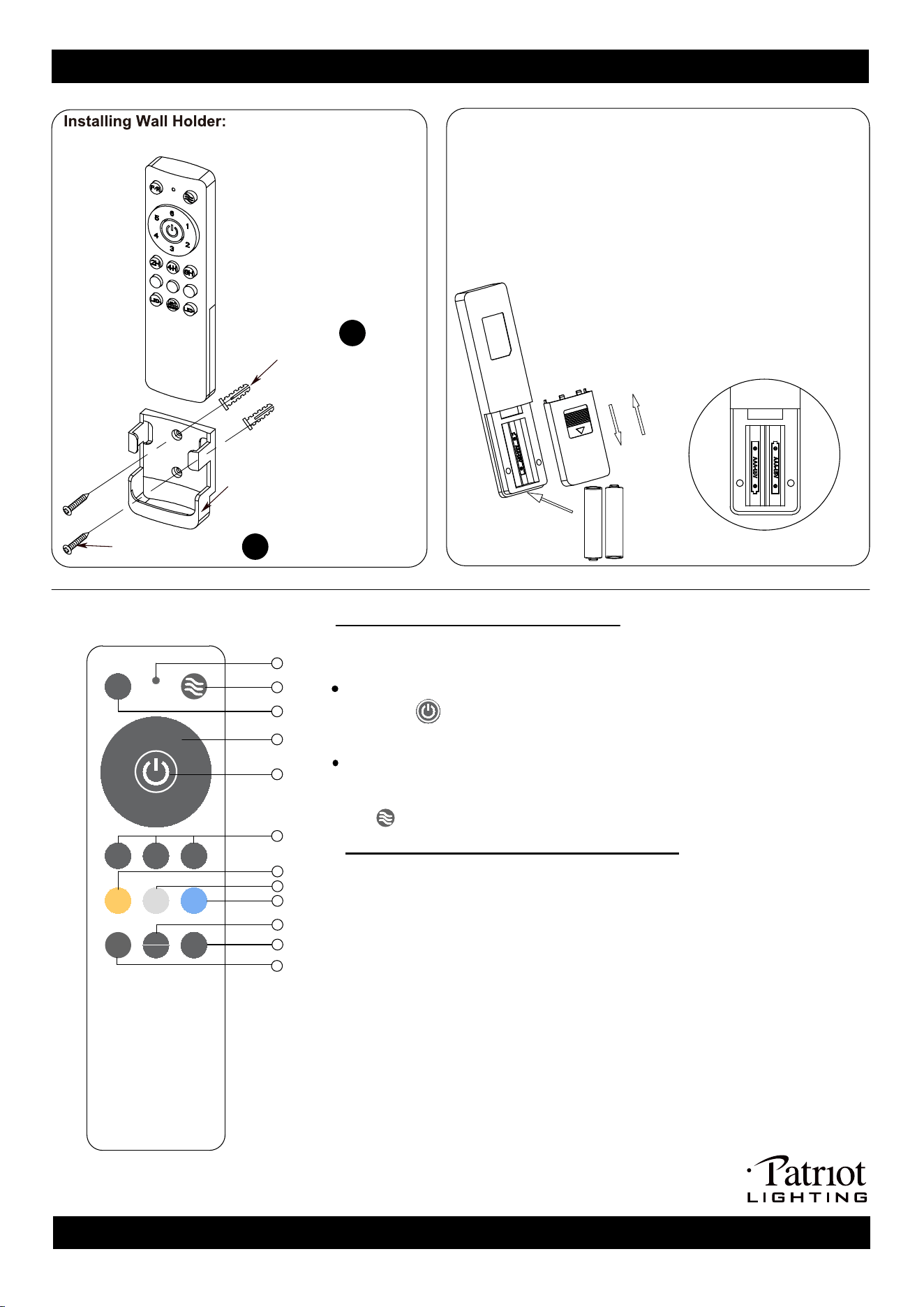
Wall Holder
(For concrete
wall
only)
1. Remove the battery cover.
2. Install two 1.5V AAA batteries (sold separately), fig 1.
3. Re-install the battery cover.
NOTE: After the battery is installed, press any key to make the
transmitter work on, and the indicate light will be on.
If the indicate light is not on, please check whether the positive
and negative electrodes of the battery are inverted, or the battery
is loose and out of position.
3
Transmitter
After code successfully, the new transmitter will control the fan only, and the
old transmitter can not control the fan.
Functions of receiver and transmitter:
1.
Indicate light:
The Indicate light will light up when you press any buttons.
2. Natural wind and on/off buzzer: Turn on ceiling fan to natural wind mode,
press and hold on the key 3 seconds on/off buzzer.
3. F/R: Switch the Fan direction.
4. 6 speed settings (1-the slowest speed, 6-the fastest speed).
5. Fan off: Turn off fan.
6. The Light and fan will turn off after two/four/eight hours.
7. Yellow: Turn the light to warm.
8. White: Turn the light to neutral.
9. Blue: Turn the light to cool.
10. Light: on/off the light.
11. LED-: Press and hold to dim light to the desired level.
12. LED+: Press and
hold to brighten light to the desired level.
7
8
9
10
11
12
1
2
Anchor (small) A
Tapping Screw(small) B
Attach wall holder using the two tapping screws (B) and anchor(A).
Transmitter decoding operation:
If the transmitter you received does not work or a new transmitter needs to be
If you don't like the sound of the buzzer, press and hold on the key of Natural
wind ( ) 3 seconds on/off buzzer.
decoding as follows.
Within 10 seconds after the receiver is powered on, press and hold on the key
of fan off ( ) (5) for 3 seconds to code. lf code successfuly, you will hear a
sound "beep" from buzzer.
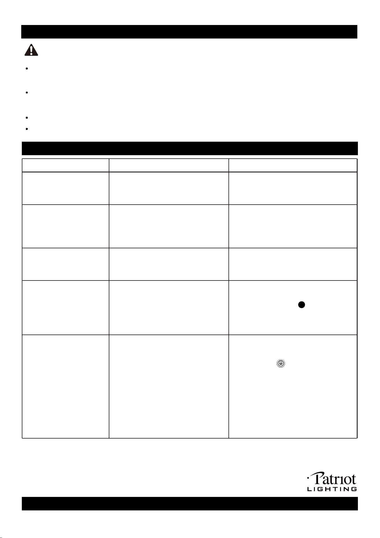
CARE AND MAINTENANCE
Trouble shooting
6
WARNING: Make sure the power is off before cleaning your fan.
Because of the fan’s natural movement, some connections may become loose. Check the support connections,
brackets, and blade attachments twice a year. Make sure they are secure. It is not necessary to remove the fan
from the ceiling.
Clean your fan periodically to help maintain its new appearance over the years. Do not use water when cleaning,
as this could damage the motor, or possibly cause an electrcal shock. Use only a soft brush or lint-free cloth to
avoid
scratching the finish. The plating is sealed with a lacquer to minimize discoloration or tarnishing.
You do not need to oil your fan. The motor has permanently-lubricated sealed ball bearings.
Always unplug the fan before cleaning, disassembly or servicing.
PROBLEM POSSIBLE CAUSE CORRECTIVE ACTION
The lights don't work and the
fans don't turn
1. The power is off or the fuse is blown.
2. There is a faulty wire connection.
1. Transmitter battery is dead.
2. There is a faulty wire connection.
1. Motor fixing screws are not tightened.
2. Auxiliary screws for hanging board are
not installed.
3. The fan blade fixing cover is not
tightened.
1. Power surge may have cleared
memory and remote needs to be
re-synced to the receiver.
2. Battery in remote control needs to
be replaced.
3. Interference from another remote.
1. Turn off the power and turn it on, and then
within 10 seconds press and hold on the
key of fan off ( ) for 3 seconds to code.
If code successfully, you will hear a sound
“beep” from buzzer (see page 5).
2. Insert new battery in battery compartment
of the remote control (see page 5).
3. If there are several fans in proximity,
turn power off to other fans and
re-sync the remote (see Corrective
Action 1 above).
1. Remove the fan blades and tighten the
loose motor fixing screws.
2. Install the set screws( )according to the
instructions on page 4.
3. Tighten the fan blade fixing cover
counterclockwise.
1. Turn the power on or check the fuse.
2. Turn the power off. Loosen the canopy
and check all connections.
1. Replace new bettery.
2. Turn the power off. Loosen the canopy,
check whether the connection cable
between the motor and the drive is loose
or fallen.
The fan operates correctly,
but the lights are not working
The fan sounds noisy
Remote control does not work
The light is on, but the fan is
broken
There is a faulty wire connection.
Turn the power off. Loosen the canopy,
check whether the lamp and the driver
cable are loose or fallen.
CC
LIMITED LIFETIME WARRANTYCE
7
The limited lifetime warranty covers this ceiling fan, for residential use by the original purchaser, against
defects in material or workmanship as follows:
If your Patriot Lighting Ceiling Fan motor fails at anytime during the lifetime of the original purchaser
due to defects in material or workmanship, we will provide a replacement part free of charge.
If your fan blades, pull chain switch, reverses witch, or any accessory, except glass globes and light
bulbs, fails at any time within one year after the original date of purchase due to a defect in material and
workmanship, we will repairor, if we choose, replace the defective blades, switch, or accessory free of
charge, with the exception of take down/reinstallation services.
If the original purchaser ceases to own the fan, this warranty and any implied warranty, including but not
limited to any implied warranty of merchantability or fitness for a particular purpose, become void. This
warranty and any implied warranty, including but not limited to any implied warranty of merchantability
or fitness for a particular purpose, do not cover glass globes, light bulbs, or finish on any metal portions
of the fan.
This warranty is in lieu of express warranties. The duration of any implied warranty of merchantability
or fitness for a particular purpose, with respect to any Patriot Lighting Ceiling Fan motor, blades, switch,
or accessories, is expressly limited to the period of the express warranty set forth above for such motor,
blades, switch, or accessories.
This warranty excludes defects, malfunctions, or failures of any Patriot Lighting Fan that are caused by
repairs by persons not authorized by us, use of parts or accessories not authorized by us, mishandling,
improper installation, modifications or damage to the fan while in your possession, or unreasonable use,
including failure to provide necessary maintenance.
To obtain service, contact the service department. You will be responsible for all insurance and freightor
other transportation charges to our factory or service center. A copy of sales receipt is required in order
to obtain service. We will return your fan freight prepaid. Your fan should be properly packed to avoid
damage in transit, for we will not be responsible for any such damages.
In no event shall Patriot Lighting Fan be liable for consequential or incidental damages.
Some states do not allow the exclusion or limitation of consequential or incidental damages, in which
case the above limitation or exclusion may not apply.
This warranty gives you specific legal rights and you may also have other rights which vary from state to
state.
Lighting Fixture Warranty
Patriot Lighting fixtures, components, and electronic products, when properly installed and under normal conditions
of use, are warranted to be free from defects in materials and workmanship for one year from date of sale.
Ceiling Fan Warranty
This Limited Lifetime Warranty includes motor and motor-related parts only, which will be replaced or repaired as
determined by Patriot Lighting during the period in which this warranty is in effect, as further defined below.