PAGE: 1 / 12
LIMITED LIFETIME WARRANTY
Model No.: #
355-0740
PAGE: 2 / 12
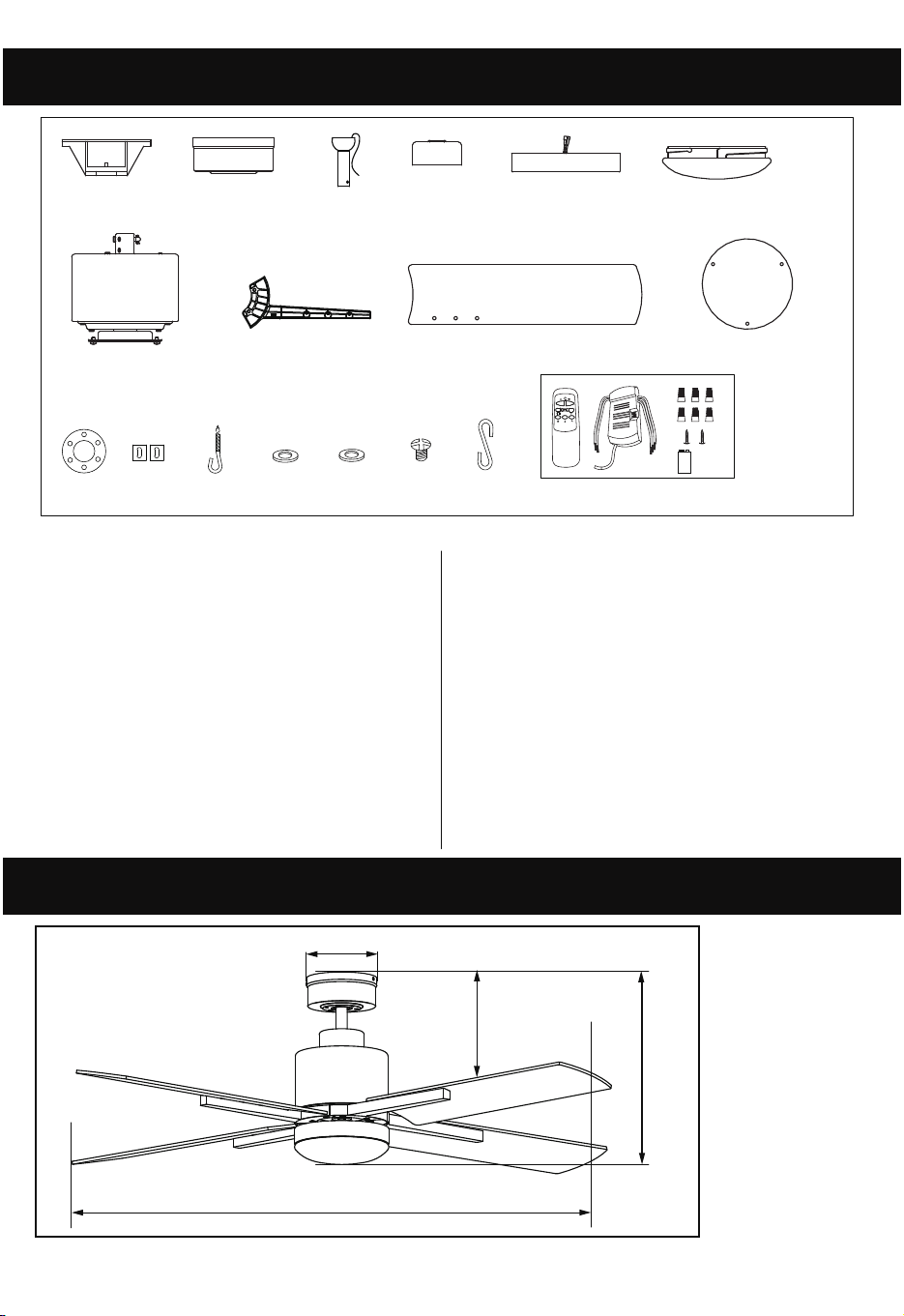
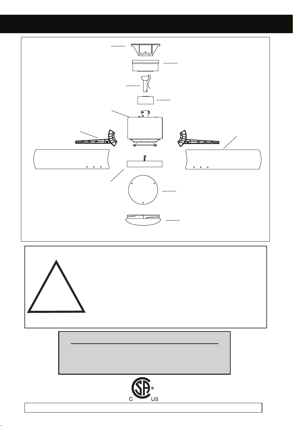
Unpack your fan and check the contents. You should have the following items.
Package Contents:
Dimension Reference (Installed with 4” Downrod):
1.) Mounting Bracket
2.) Canopy
3.) Downrod Assembly (Included
Hanger Ball, 4” Downrod, Hanger Pin
4.) Yoke Cover
5.) Light Kit
6.) Diffuser
7.) Fan Motor Assembly
8.) Blade Bracket (5PCS)
9.) Fan Blades (5PCS)
& Lock Pin)
10.) Glass Panel
09-21
To obtain Service, please contact or call Patriot Lighting Service Department:
1-800-267-4427, 8am to 5pm Eastern Time.
The limited lifetime warranty covers this ceiling fan, for residential use by the original purchaser, against defects in
material or workmanship as follows:
If your Patriot Lighting Ceiling Fan motor fails at any time during the lifetime of the original purchaser due to defects in
material or workmanship, we will provide a replacement part free of charge.
If your Fan motor fails at any time within one year after the original date of sale to the original purchaser due to defects
in material or workmanship, we will provide labor to repair the defect, with the exception of take down/reinstallation,
free of charge. The original purchaser will be responsible for all labor costs after this one year period.
If no replacement parts are provided for any part of your Fan motor that fails at any time during your lifetime due to
defects in material or workmanship, we will refund the original purchase price of your Fan.
If your Fan blades, remote controller / pull chain switch, reverse switch, or any accessory, except glass globes and light
bulbs, fails at any time within one year after the original date of purchase due to a defect in material and workmanship,
we will repair or, if we choose, replace the defective blades, switch, or accessory free of charge, with the exception of
take down/reinstallation services.
If the original purchaser ceases to own the Fan, this warranty and any implied warranty, including but not limited to any
implied warranty of merchantability or fitness for a particular purpose, become void. This warranty and any implied
warranty, including but not limited to any implied warranty of merchantability or fitness for a particular purpose, do not
cover glass globes, light bulbs, or finish on any metal portions of the Fan.
This warranty is in lieu of express warranties. The duration of any implied warranty of merchantability or fitness for a
particular purpose, with respect to any Patriot Lighting Ceiling Fan motor, blades, switch, or accessories, is expressly
limited to the period of the express warranty set forth above for such motor, blades, switch, or accessories.
This warranty excludes defects, malfunctions, or failures of any Patriot Lighting Fan that are caused by repairs by
persons not authorized by us, use of parts or accessories not authorized by us, mishandling, improper installation,
modifications or damage to the Fan while in your possession, or unreasonable use, including failure to provide
necessary maintenance.
To obtain service, contact Patriot Lighting Service Department at 1-800-887-6326, 9AM-5PM CST. You will be responsible
for all insurance and freight or other transportation charges to our factory or service center. A copy of sales
receipt is required in order to obtain service. We will return your Fan freight prepaid. Your Fan should be properly
packed to avoid damage in transit, for we will not be responsible for any such damages.
In no event shall Patriot Lighting Fan be liable for consequential or incidental damages.
Some states do not allow the exclusion or limitation of consequential or incidental damages, in which case the above
limitation or exclusion may not apply.
This warranty gives you specific legal rights and you may also have other rights which vary from state to state.
A. 14 in. B. 10 3/4 in. C. 52 in. D. 5 1/4 in.
A
D
B
C
18
12
13
10
14 15 16
3
4
2
1
5
7
8
9
6
11
17
11.)
12.)
Rubber Gasket
14.)
15.) Metal Washer
16.) Bade Bracket Screw
Rubber Bushing
13.)
J-Hook
Fiber Washer
18.) Remote Control (Includes Remote,
Receiver, Wire Nuts, Screws and
Battery)
17.) Temporary Hook
PAGE: 1 / 12
LIMITED LIFETIME WARRANTY
Model No.: #
355-0740
PAGE: 2 / 12
Unpack your fan and check the contents. You should have the following items.
Package Contents:
Dimension Reference (Installed with 4” Downrod):
1.) Mounting Bracket
2.) Canopy
3.) Downrod Assembly (Included
Hanger Ball, 4” Downrod, Hanger Pin
4.) Yoke Cover
5.) Light Kit
6.) Diffuser
7.) Fan Motor Assembly
8.) Blade Bracket (5PCS)
9.) Fan Blades (5PCS)
& Lock Pin)
10.) Glass Panel
09-21
To obtain Service, please contact or call Patriot Lighting Service Department:
1-800-267-4427, 8am to 5pm Eastern Time.
The limited lifetime warranty covers this ceiling fan, for residential use by the original purchaser, against defects in
material or workmanship as follows:
If your Patriot Lighting Ceiling Fan motor fails at any time during the lifetime of the original purchaser due to defects in
material or workmanship, we will provide a replacement part free of charge.
If your Fan motor fails at any time within one year after the original date of sale to the original purchaser due to defects
in material or workmanship, we will provide labor to repair the defect, with the exception of take down/reinstallation,
free of charge. The original purchaser will be responsible for all labor costs after this one year period.
If no replacement parts are provided for any part of your Fan motor that fails at any time during your lifetime due to
defects in material or workmanship, we will refund the original purchase price of your Fan.
If your Fan blades, remote controller / pull chain switch, reverse switch, or any accessory, except glass globes and light
bulbs, fails at any time within one year after the original date of purchase due to a defect in material and workmanship,
we will repair or, if we choose, replace the defective blades, switch, or accessory free of charge, with the exception of
take down/reinstallation services.
If the original purchaser ceases to own the Fan, this warranty and any implied warranty, including but not limited to any
implied warranty of merchantability or fitness for a particular purpose, become void. This warranty and any implied
warranty, including but not limited to any implied warranty of merchantability or fitness for a particular purpose, do not
cover glass globes, light bulbs, or finish on any metal portions of the Fan.
This warranty is in lieu of express warranties. The duration of any implied warranty of merchantability or fitness for a
particular purpose, with respect to any Patriot Lighting Ceiling Fan motor, blades, switch, or accessories, is expressly
limited to the period of the express warranty set forth above for such motor, blades, switch, or accessories.
This warranty excludes defects, malfunctions, or failures of any Patriot Lighting Fan that are caused by repairs by
persons not authorized by us, use of parts or accessories not authorized by us, mishandling, improper installation,
modifications or damage to the Fan while in your possession, or unreasonable use, including failure to provide
necessary maintenance.
To obtain service, contact Patriot Lighting Service Department at 1-800-887-6326, 9AM-5PM CST. You will be responsible
for all insurance and freight or other transportation charges to our factory or service center. A copy of sales
receipt is required in order to obtain service. We will return your Fan freight prepaid. Your Fan should be properly
packed to avoid damage in transit, for we will not be responsible for any such damages.
In no event shall Patriot Lighting Fan be liable for consequential or incidental damages.
Some states do not allow the exclusion or limitation of consequential or incidental damages, in which case the above
limitation or exclusion may not apply.
This warranty gives you specific legal rights and you may also have other rights which vary from state to state.
A. 14 in. B. 10 3/4 in. C. 52 in. D. 5 1/4 in.
A
D
B
C
18
12
13
10
14 15 16
3
4
2
1
5
7
8
9
6
11
17
11.)
12.)
Rubber Gasket
14.)
15.) Metal Washer
16.) Bade Bracket Screw
Rubber Bushing
13.)
J-Hook
Fiber Washer
18.) Remote Control (Includes Remote,
Receiver, Wire Nuts, Screws and
Battery)
17.) Temporary Hook
PAGE: 3 / 12 PAGE: 4 / 12
NOTE: FOR OPTIMUM QUIETNESS, FULLY ASSEMBLE FAN AND RUN 24 HOURS
TOOLS AND MATERIALS REQUIRED
- Philips Screwdriver
- Blade Screwdriver
- Step Ladder
- Wire Cutters
- Wiring supplies as required by electrical code.
!
INSTRUCTIONS PERTAINING TO RISK OF FIRE OR INJURY TO PERSONS
READ ALL INSTRUCTIONS
IMPORTANT SAFETY
INSTRUCTIONS
SAVE THESE INSTRUCTIONS
INSTALLATION AND WIRING TO BE IN ACCORDANCE WITH CEC,
NEC, LOCAL ELECTRICAL CODES and ANSI/NFPA 70.
Consult a qualified electrician if you are not familiar with wiring.
IMPORTANT SAFETY INSTRUCTIONS
WARNING
1. Turn off power at main electrical service box before starting installation.
2. Electrical connections must comply with local code ordinances, national electrical
codes, CEC, NEC and ANSI/NFPA 70.
3. Make sure the installation site you choose allows the fan blades to rotate freely
without any obstructions.
4. When mounting the fan on a ceiling outlet box, Use an approved (CSA for Canada
and UL for U.S.) ceiling fan box marked "FOR FAN SUPPORT". Ensure the outlet
box is securely installed in place such that it is able to support at least the fan weight.
5. Total Fan Weight For Reference: 52" approximate 7.1 kgs (15.66lbs).
1. To reduce the risk of fire or electrical shock, use only CQ007 remote control (supplied)
for replacement if required.
3. Mount with the lowest moving parts at least 2.10 Meters (7 Feet) above floor or
grade level.
4. Fan must be turned off and rotating blades stopped before changing blades direction.
Exploded View Detail
2. WARNING: RISK OF FIRE, ELECTRIC SHOCK, OR PERSONAL INJURY. THE
FAN IN THIS BOX MAY BE EITHER DIRECTLY SUPPORTED FROM A
STRUCTURAL FRAMING MEMBER OF A BUILDING AND/OR MAY BE MOUNTED
TO AN OUTLET BOX MARKED ACCEPTABLE FOR FAN SUPPORT OF 35 LBS
(15.9 KG) OR LESS. Most outlet boxes commonly used for the support of luminaires
may not be acceptable for fan support and may need to be replaced. Consult a
qualified electrician if in doubt.
Glass Panel
Diffuser
Mounting Bracket
Canopy
Downrod
Yoke Cover
Fan Motor
Fan Blades
Light Kit
Blade Bracket
PAGE: 5 / 12 PAGE: 6 / 12
ASSEMBLY INSTRUCTIONS ASSEMBLY INSTRUCTIONS (continued)
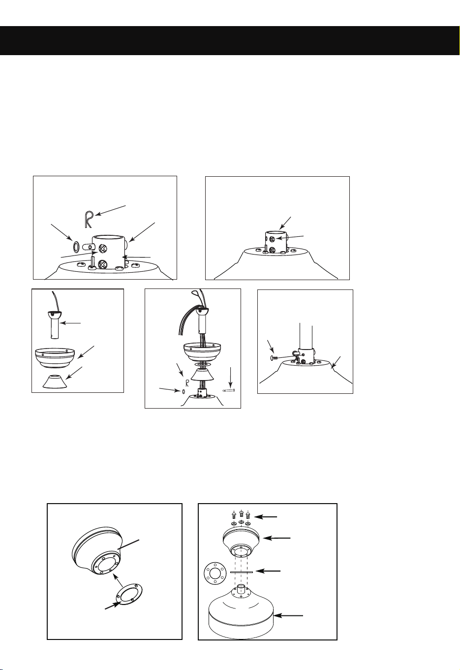
1. MOUNTING
DOWNROD MOUNT
a.
b.
c.
d.
e.
- Loosen jam screws in yoke until it is flush with the inside surface.
- Obtain downrod, canopy and yoke cover.
- Place downrod inside canopy and yoke cover.
- Route wires exiting motor through yoke cover, canopy and downrod.
- Insert bolt through hole in yoke and downrod. Be careful not to damage or cut the fan wires.
- Place flat washer over end of bolt and insert cotter pin through hole in the end of the bolt.
- Secure downrod in position by tightening jam screws. Slide yoke cover down so it is flush
with the motor housing.
A
B
FLUSH MOUNT
- Remove rubber ring from canopy
- Remove the Motor cover housing by aligning 3 screws
- Place rubber bushing on Motor housing aligning the 3 smaller holes.
- Place canopy on Motor housing, align the 3 smaller holes on canopy
to holes on Motor housing.
- Remove the 3 screws and washers from the top of the motor. Secure Canopy to the
motor housing by replacing 3 screws and washers in the 3 smaller holes in canopy.
Canopy
Rubber Ring
Motor
Canopy
Yoke Screws
& Washers
Rubber
f.
g.
Bushing
Motor
Bolt
Yoke
Jam
Screw
Jam
Screw
Downrod
Canopy
Yoke
Cover
Bolt
Flat
Washer
Cotter Pin
Yoke
Jam
Screw
Cotter
Flat
Washer
Pin
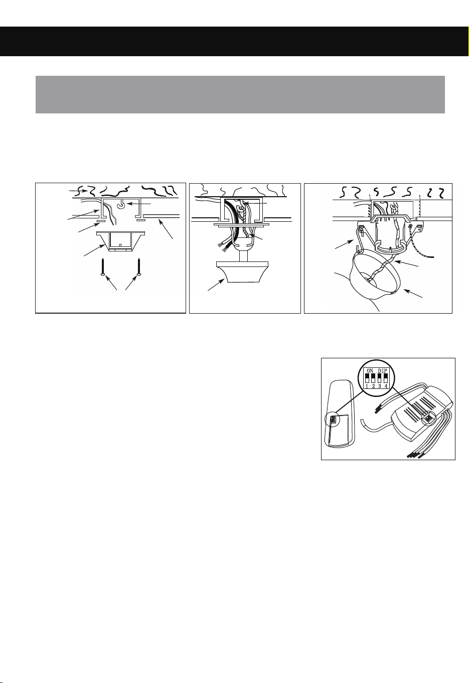
2. INSTALL MOUNTING BRACKET
- Install J-Hook through center of outlet box into the wooden joist.
- Secure mounting bracket and rubber gaskets to outlet box.
- Hang fan on mounting bracket and install safety cable onto the J-Hook.
WARNING: To Reduce The Risk Of Fire, Electric Shock, Or Personal Injury, Mount
To UL/CSA Listed Outlet Box Marked Acceptable For Fan Support And Use Mounting
Screws Provided With The Outlet Box.
Wood
Joist
Outlet
Box
Rubber
Gasket
Mounting
Bracket
Outlet box screws
(not provided)
Ceiling
J-Hook
- This fan is equipped with a remote control unit for controlling the fan speeds and light kit.
- To set the code on the hand-held remote and the receiver:
#1- Remove the battery cover on the hand-held remote
(Press firmly below the arrow and slide the battery cover off).
#2- Set code switches to desired position on the receiver and
on the remote.
#3- Replace the battery cover on the hand-held remote.
- Make the following wire connections to the receiver unit using the wire nuts supplied.
- Connect GREEN wire (Fan & Receiver) to BARE (ground) wire.
- Connect BLACK receiver unit wire to BLACK supply wire.
- Connect WHITE receiver unit wire to WHITE supply wire.
- Connect WHITE receiver unit wire (MOTOR N) to WHITE fan wire.
- Connect BLACK receiver unit wire (MOTOR L) to BLACK fan wire.
- Connect BLUE receiver unit wire (FOR LIGHT) to BLUE light wire.
- After making wire the connections, push wires neatly back into the outlet box ensuring
wire splices (wire nuts) are turned upward.
3. ELECTRICAL HOOK-UP
A
B
a.
Canopy
J-Hook
Safety
Cable
b.
Canopy
Safety
Cable
c.
Temporary
Hook
Diagram b is for Downrod Mount.
Diagram c is for Flush Mount.
a.
PAGE: 5 / 12 PAGE: 6 / 12
ASSEMBLY INSTRUCTIONS ASSEMBLY INSTRUCTIONS (continued)
1. MOUNTING
DOWNROD MOUNT
a.
b.
c.
d.
e.
- Loosen jam screws in yoke until it is flush with the inside surface.
- Obtain downrod, canopy and yoke cover.
- Place downrod inside canopy and yoke cover.
- Route wires exiting motor through yoke cover, canopy and downrod.
- Insert bolt through hole in yoke and downrod. Be careful not to damage or cut the fan wires.
- Place flat washer over end of bolt and insert cotter pin through hole in the end of the bolt.
- Secure downrod in position by tightening jam screws. Slide yoke cover down so it is flush
with the motor housing.
A
B
FLUSH MOUNT
- Remove rubber ring from canopy
- Remove the Motor cover housing by aligning 3 screws
- Place rubber bushing on Motor housing aligning the 3 smaller holes.
- Place canopy on Motor housing, align the 3 smaller holes on canopy
to holes on Motor housing.
- Remove the 3 screws and washers from the top of the motor. Secure Canopy to the
motor housing by replacing 3 screws and washers in the 3 smaller holes in canopy.
Canopy
Rubber Ring
Motor
Canopy
Yoke Screws
& Washers
Rubber
f.
g.
Bushing
Motor
Bolt
Yoke
Jam
Screw
Jam
Screw
Downrod
Canopy
Yoke
Cover
Bolt
Flat
Washer
Cotter Pin
Yoke
Jam
Screw
Cotter
Flat
Washer
Pin
2. INSTALL MOUNTING BRACKET
- Install J-Hook through center of outlet box into the wooden joist.
- Secure mounting bracket and rubber gaskets to outlet box.
- Hang fan on mounting bracket and install safety cable onto the J-Hook.
WARNING: To Reduce The Risk Of Fire, Electric Shock, Or Personal Injury, Mount
To UL/CSA Listed Outlet Box Marked Acceptable For Fan Support And Use Mounting
Screws Provided With The Outlet Box.
Wood
Joist
Outlet
Box
Rubber
Gasket
Mounting
Bracket
Outlet box screws
(not provided)
Ceiling
J-Hook
- This fan is equipped with a remote control unit for controlling the fan speeds and light kit.
- To set the code on the hand-held remote and the receiver:
#1- Remove the battery cover on the hand-held remote
(Press firmly below the arrow and slide the battery cover off).
#2- Set code switches to desired position on the receiver and
on the remote.
#3- Replace the battery cover on the hand-held remote.
- Make the following wire connections to the receiver unit using the wire nuts supplied.
- Connect GREEN wire (Fan & Receiver) to BARE (ground) wire.
- Connect BLACK receiver unit wire to BLACK supply wire.
- Connect WHITE receiver unit wire to WHITE supply wire.
- Connect WHITE receiver unit wire (MOTOR N) to WHITE fan wire.
- Connect BLACK receiver unit wire (MOTOR L) to BLACK fan wire.
- Connect BLUE receiver unit wire (FOR LIGHT) to BLUE light wire.
- After making wire the connections, push wires neatly back into the outlet box ensuring
wire splices (wire nuts) are turned upward.
3. ELECTRICAL HOOK-UP
A
B
a.
Canopy
J-Hook
Safety
Cable
b.
Canopy
Safety
Cable
c.
Temporary
Hook
Diagram b is for Downrod Mount.
Diagram c is for Flush Mount.
a.
PAGE: 7 / 12 PAGE: 8 / 12
ASSEMBLY INSTRUCTIONS (continued) ASSEMBLY INSTRUCTIONS (continued)
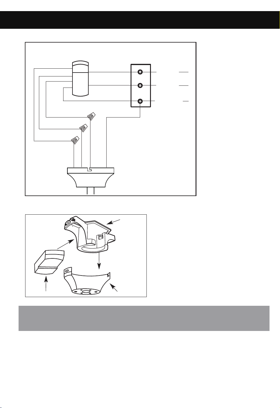
3. ELECTRICAL HOOK-UP
B
NOTE: Once ground wires are connected, carefully tuck all wires and marrettes into
the metal outlet box making sure that the wires are clear of the hemisphere and
downrod when positioned in mounting bracket.
- Place two screws and washers on mounting plate (marked B on diagram) which
- In cold weather: Set to reverse rotation (clockwise). Airflow will be directed
upward, circulating warm air.
- In warm weather: Set to forward rotation (counter-clockwise). Airflow will be
directed downward, circulating cold air.
correspond with slots in canopy. Screw in two turns.
- Position canopy to mounting plate aligning slots to screws (marked B on diagram)
then turn to lock.
- Position and tighten the two screws and washers (marked A on diagram) then tighten
the two screws (marked B on diagram).
4. MOUNTING FAN ASSEMBLY
C
- Push all connected wires up into ceiling box.
- Slide the receiver into the mounting bracket as shown below.
Receiver
Mounting
Bracket
Canopy
c.
5. ENGAGE HEMISPHERE (Downrod Mount Only)
- The hemisphere needs to be engaged before receiver will fit into mounting bracket.
- Carefully rotate fan assembly until groove in hemisphere locks over tab of canopy assembly.
WARNING: Failure to seat tab in groove could cause damage to electrical wires and
possible shock or fire hazard.
Downrod
Hemisphere
Groove
NOTE: When installing fan on sloped ceiling, make sure tab on hanger bracket faces towards
the top of the slope. Depending on the slope, a longer downrod may be required to prevent
fan blades from hitting the ceiling.
a.
b.
(A)
(B)
(B)
Washers
(A)
Fan
BOX
OUTLET
WHITE
BLACK
GROUND
WHITE
BLACK
GREEN
RECEIVER
WHITE
BLACK
BLUE
WHITE
BLACK
BLUE
GREEN
120V
SUPPLY
CIRCUIT
b.
REMOTE CONTROL
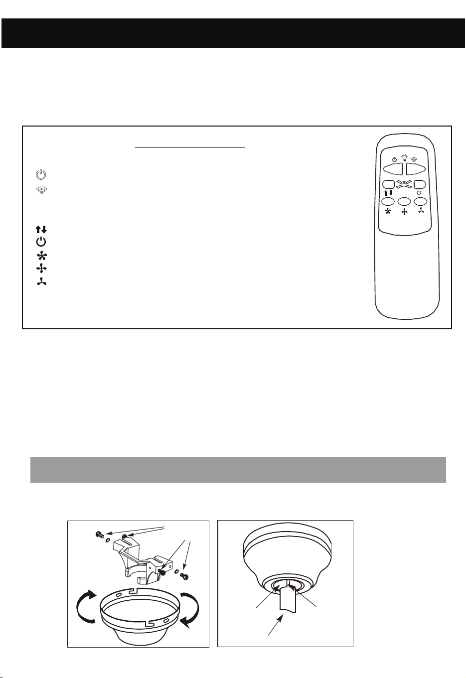
Install 9 V battery. Operation buttons on the remote:
- ON/OFF the light
- Setting color temperature and dimming
Short press: color temperature (3000k,4000k or 5000k options);
Long press: dimming
- Direction of the fan (reverse button)
- ON/OFF the fan
- High speed
- Medium speed
- Low speed
*Hold down dimming button to increase or decrease the lighting.
The light has a memory function so the light will stay at the same
brightness as the last time it was turned off.
D FUNCTION INSTRUCTION OF TRANSMITTER
PAGE: 7 / 12 PAGE: 8 / 12
ASSEMBLY INSTRUCTIONS (continued) ASSEMBLY INSTRUCTIONS (continued)
3. ELECTRICAL HOOK-UP
B
NOTE: Once ground wires are connected, carefully tuck all wires and marrettes into
the metal outlet box making sure that the wires are clear of the hemisphere and
downrod when positioned in mounting bracket.
- Place two screws and washers on mounting plate (marked B on diagram) which
- In cold weather: Set to reverse rotation (clockwise). Airflow will be directed
upward, circulating warm air.
- In warm weather: Set to forward rotation (counter-clockwise). Airflow will be
directed downward, circulating cold air.
correspond with slots in canopy. Screw in two turns.
- Position canopy to mounting plate aligning slots to screws (marked B on diagram)
then turn to lock.
- Position and tighten the two screws and washers (marked A on diagram) then tighten
the two screws (marked B on diagram).
4. MOUNTING FAN ASSEMBLY
C
- Push all connected wires up into ceiling box.
- Slide the receiver into the mounting bracket as shown below.
Receiver
Mounting
Bracket
Canopy
c.
5. ENGAGE HEMISPHERE (Downrod Mount Only)
- The hemisphere needs to be engaged before receiver will fit into mounting bracket.
- Carefully rotate fan assembly until groove in hemisphere locks over tab of canopy assembly.
WARNING: Failure to seat tab in groove could cause damage to electrical wires and
possible shock or fire hazard.
Downrod
Hemisphere
Groove
NOTE: When installing fan on sloped ceiling, make sure tab on hanger bracket faces towards
the top of the slope. Depending on the slope, a longer downrod may be required to prevent
fan blades from hitting the ceiling.
a.
b.
(A)
(B)
(B)
Washers
(A)
Fan
BOX
OUTLET
WHITE
BLACK
GROUND
WHITE
BLACK
GREEN
RECEIVER
WHITE
BLACK
BLUE
WHITE
BLACK
BLUE
GREEN
120V
SUPPLY
CIRCUIT
b.
REMOTE CONTROL
Install 9 V battery. Operation buttons on the remote:
- ON/OFF the light
- Setting color temperature and dimming
Short press: color temperature (3000k,4000k or 5000k options);
Long press: dimming
- Direction of the fan (reverse button)
- ON/OFF the fan
- High speed
- Medium speed
- Low speed
*Hold down dimming button to increase or decrease the lighting.
The light has a memory function so the light will stay at the same
brightness as the last time it was turned off.
D FUNCTION INSTRUCTION OF TRANSMITTER
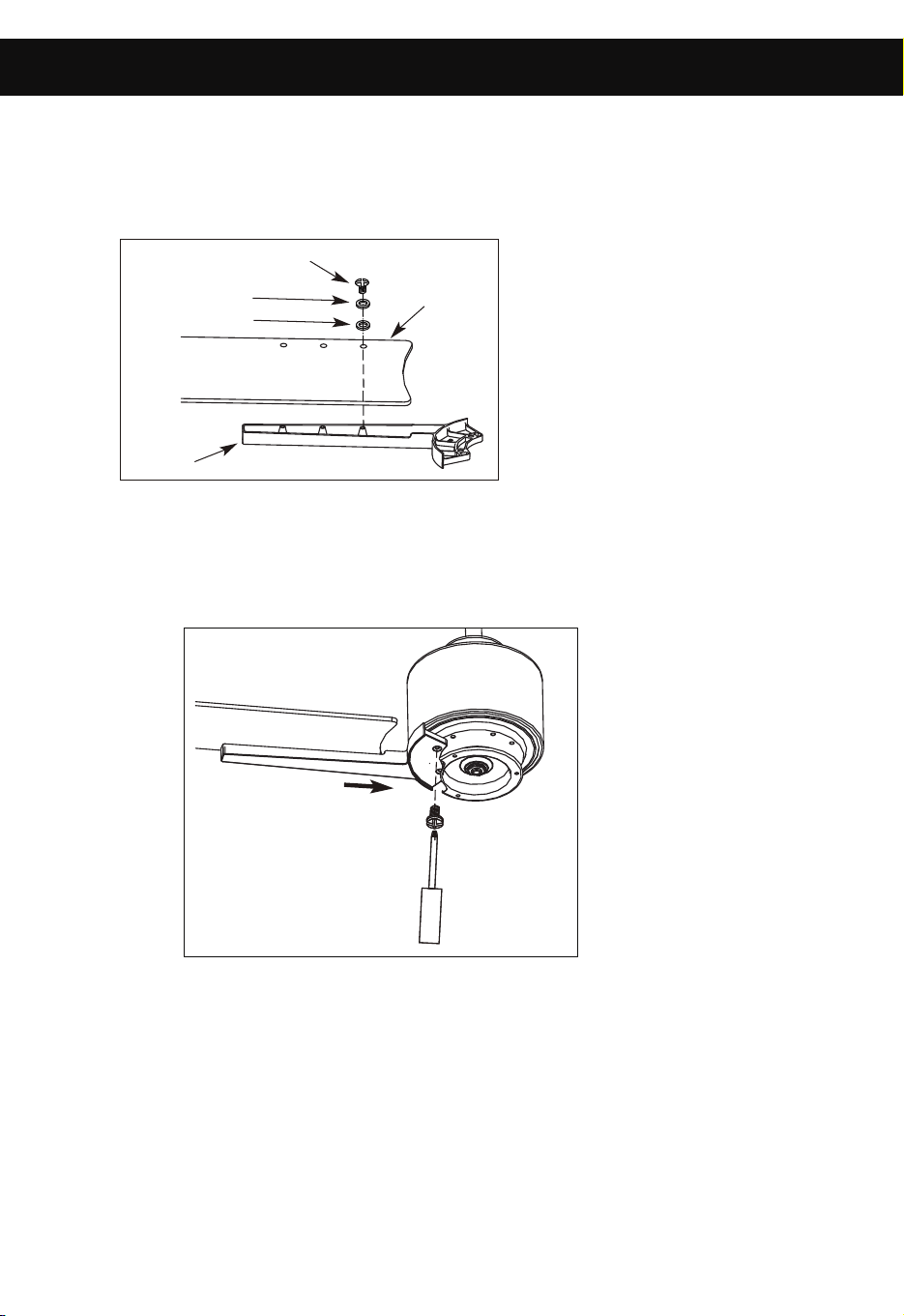
- Place blade bracket screw through flat washer, fiber washer and blade.
- Align with corresponding hole in blade bracket.
- Repeat with (2) remaining screws and tighten.
Blade
Bracket
Fiber Washer
Flat Washer
Blade Bracket Screw
Blade
6. MOUNT BLADE BRACKETS TO BLADES
PAGE: 9 / 12 PAGE: 10 / 12
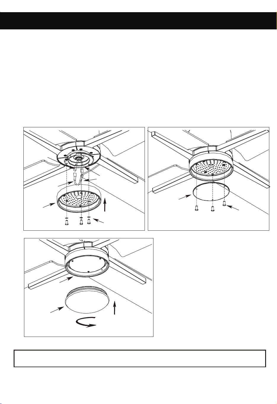
ASSEMBLY INSTRUCTIONS
7. MOUNTING BLADES TO MOTOR
WARNING: Ensure that all connections, set screws and screws are securely tightened
before the next step.
WARNING: BE SURE TO TURN OFF POWER BEFORE INSTALLING
- Insert the blade arm into the fan as shown.
- Tighten the blade arm to motor with the screw and lock washer as shown.
- Slightly turn the blade after installation and repeat the same step for the other blades.
- Remove light kit screws and washers.
- Connect polarized connectors of light kit to corresponding connectors
found in switch housing.
DETACHABLE LIGHT KITS
for your model)
(Refer to one of the following light kits
- Install the light kit to the fan motor assembly by tightening 3 screws
and washers.
- Remove the 3 plastic screw from light kit.
- Install the glass panel on the light kit by tightening the 3 plastic screws.
- Screw the diffuser to the Light kit.
ASSEMBLY INSTRUCTIONS (continued)
-
Screw and Washers
Kit
Light Kit
Plastic Screw
Glass Panel
Red or Blue
Wires
White Wires
Black or
Blue Wires
a.
c.
. LIGHT KITS
8
Diffuser
Light Kit
- Place blade bracket screw through flat washer, fiber washer and blade.
- Align with corresponding hole in blade bracket.
- Repeat with (2) remaining screws and tighten.
Blade
Bracket
Fiber Washer
Flat Washer
Blade Bracket Screw
Blade
6. MOUNT BLADE BRACKETS TO BLADES
PAGE: 9 / 12 PAGE: 10 / 12
ASSEMBLY INSTRUCTIONS
7. MOUNTING BLADES TO MOTOR
WARNING: Ensure that all connections, set screws and screws are securely tightened
before the next step.
WARNING: BE SURE TO TURN OFF POWER BEFORE INSTALLING
- Insert the blade arm into the fan as shown.
- Tighten the blade arm to motor with the screw and lock washer as shown.
- Slightly turn the blade after installation and repeat the same step for the other blades.
- Remove light kit screws and washers.
- Connect polarized connectors of light kit to corresponding connectors
found in switch housing.
DETACHABLE LIGHT KITS
for your model)
(Refer to one of the following light kits
- Install the light kit to the fan motor assembly by tightening 3 screws
and washers.
- Remove the 3 plastic screw from light kit.
- Install the glass panel on the light kit by tightening the 3 plastic screws.
- Screw the diffuser to the Light kit.
ASSEMBLY INSTRUCTIONS (continued)
-
Screw and Washers
Kit
Light Kit
Plastic Screw
Glass Panel
Red or Blue
Wires
White Wires
Black or
Blue Wires
a.
c.
. LIGHT KITS
8
Diffuser
Light Kit

PAGE: 11 / 12
To clean the fixture, turn off the power, wait for it to cool, and wipe the fixture
with a clean, soft cloth.
ASSEMBLY INSTRUCTIONS
CARE AND MAINTENANCE
TROUBLESHOOTING
- Check wiring connections to fan.
- Check fuses and circuit breakers.
- Check wiring connections in switch housing.
CAUTION: Turn power off for last two items.
- Check to make sure that all screws in motor housing are snug.
- Check to make sure that blade bracket screws are tight.
- Check to make sure that wire nuts in switch housing
are not rattling against wall of switch housing.
- If fan has a light kit make sure switch housing
screws and set screws are tight.
- Some fan motors are sensitive to signals from solid state
variable controls. If solid state controller is used, change to
an alternative control. (See a representative for a list of
available controls.)
- Allow a 24 hour break in period to eliminate most noises.
- Check that all blades are screwed firmly into blade brackets.
- Check that blade brackets are secured firmly to motor.
- Check distance from tip of blades to ceiling.
- Check distance between blade tip to blade tip. All
measurements should be equal. Loosen blade screws and
position blade until even then re-tighten.
- Check that the downrod hemisphere notch is engaged in canopy.
- Check to make sure that jam screws in downrod are tightened.
- Make sure canopy and mounting bracket are tightened securely
to wooden joist.
- Make sure warpage has not occurred in wooden blades. If so,
contact the customer service department for replacement parts.
TROUBLE SUGGESTIONS
1. Fan will not start
2. Fan sounds noisy
3. Fan wobbles or
shakes excessively.
PAGE: 12 / 12
This equipment has been tested and found to comply with the limits for
a Class B digital device, pursuant to Part 15 of the FCC Rules. These
limits are designed to provide reasonable protection against harmful
interference in a residential installation. This equipment generates,
uses and can radiate radio frequency energy and, if not installed and
used in accordance with the instructions, may cause harmful
interference to radio communications. However, there is no guarantee
that interference will not occur in a particular installation. If this
equipment does cause harmful interference to radio or television
reception, which can be determined by turning the equipment off and
on, the user is encouraged to try to correct the interference by one or
more of the following measures:
-- Reorient or relocate the receiving antenna.
-- Increase the separation between the equipment and receiver.
-- Connect the equipment into an outlet on a circuit different from that
to which the receiver is connected.
-- Consult the dealer or an experienced radio/TV technician for help.
CAUTION:
Any changes or modifications not expressly approved by the grantee
of this device could void the user’s authority to operate the equipment.
This device complies with Part 15 of the FCC Rules. Operation is
subject to the following two conditions: (1) This device may not cause
harmful interference, and (2) this device must accept any interference
received, including interference that may cause undesired operation.
This device contains licence-exempt transmitter(s)/receiver(s)
that comply with Innovation, Science and Economic Development
Canada’s licence-exempt RSS(s). Operation is subject to the
following two conditions:
1. This device may not cause interference.
2. This device must accept any interference, including interference
that may cause undesired operation of the device.
Supplier's Declaration of Conformity
47 CFR § 2.1077 Compliance Information
Unique Identifier: PATRIOT
Responsible Party
CanarmInc.
709 East Main Street, Teutopolis, Illinois, USA 62467
1.800.267.4427