PAGE: 1 / 9
LIMITED LIFETIME WARRANTY
Model No.: # 355-0790 355-0791
To obtain Service, please contact or call PATRIOT LIGHTING Service Department:
®
1-800-887-6326, 9 a.m.- 5 p.m. central time.
The limited lifetime warranty covers this ceiling fan, for residential use by the original purchaser, against defects in
material or workmanship as follows:
If your PATRIOT LIGHTING Ceiling Fan motor fails at any time during the lifetime of the original purchaser due to
defects in material or workmanship, we will provide a replacement part free of charge.
®
If your Fan motor fails at any time within one year after the original date of sale to the original purchaser due to defects
in material or workmanship, we will provide labor to repair the defect, with the exception of take down/reinstallation,
free of charge. The original purchaser will be responsible for all labor costs after this one year period.
If no replacement parts are provided for any part of your Fan motor that fails at any time during your lifetime due to
defects in material or workmanship, we will refund the original purchase price of your Fan.
If your Fan blades, remote control / pull chain switch, reverse switch, or any accessory, except glass globes and light
bulbs, fails at any time within one year after the original date of purchase due to a defect in material and workmanship,
we will repair or, if we choose, replace the defective blades, switch, or accessory free of charge, with the exception of
take down/reinstallation services.
If the original purchaser ceases to own the Fan, this warranty and any implied warranty, including but not limited to any
implied warranty of merchantability or fitness for a paticular purpose, become void. This warranty and any implied
warranty, including but not limited to any implied warranty of merchantability or fitness for a particular purpose, do not
cover glass globes, light bulbs, or finish on any metal portions of the Fan.
This warranty is in lieu of express warranties. The duration of any implied warranty of merchantability or fitness for a
particular purpose, with respect to any PATRIOT LIGHTING Ceiling Fan motor, blades, switch, or accessories, is
expressly limited to the period of the express warranty set forth above for such motor, blades, switch, or accessories.
This waranty excludes defects, malfunctions, or failures of any PATRIOT LIGHTING® Fan that are caused by repairs
by persons not authorized by us, use of parts or accessories not authorized by us, mishandling, improper installation,
modifications or damage to the Fan while in your possession, or unreasonable use, including failure to provide
necessary maintenance.
To obtain service, contact PATRIOT LIGHTING Service Department at 1-800-887-6326, 9AM-5PM CST. You will be
responsible for all insurance and freight or other transportation charges to our factory or service center. A copy of sales
receipt is required in order to obtain service. We will return your Fan freight prepaid. Your Fan should be properly
packed to avoid damage in transit, for we will not be responsible for any such damages.
®
®
In no event shall PATRIOT LIGHTING Fan be liable for consequential or incidental damages.
Some states do not allow the exclusion or limitation of consequential or incidental damages, in which case the above
limitation or exclusion may not apply.
This warranty gives you specific legal rights and you may also have other rights which vary from state to state.
®
241230
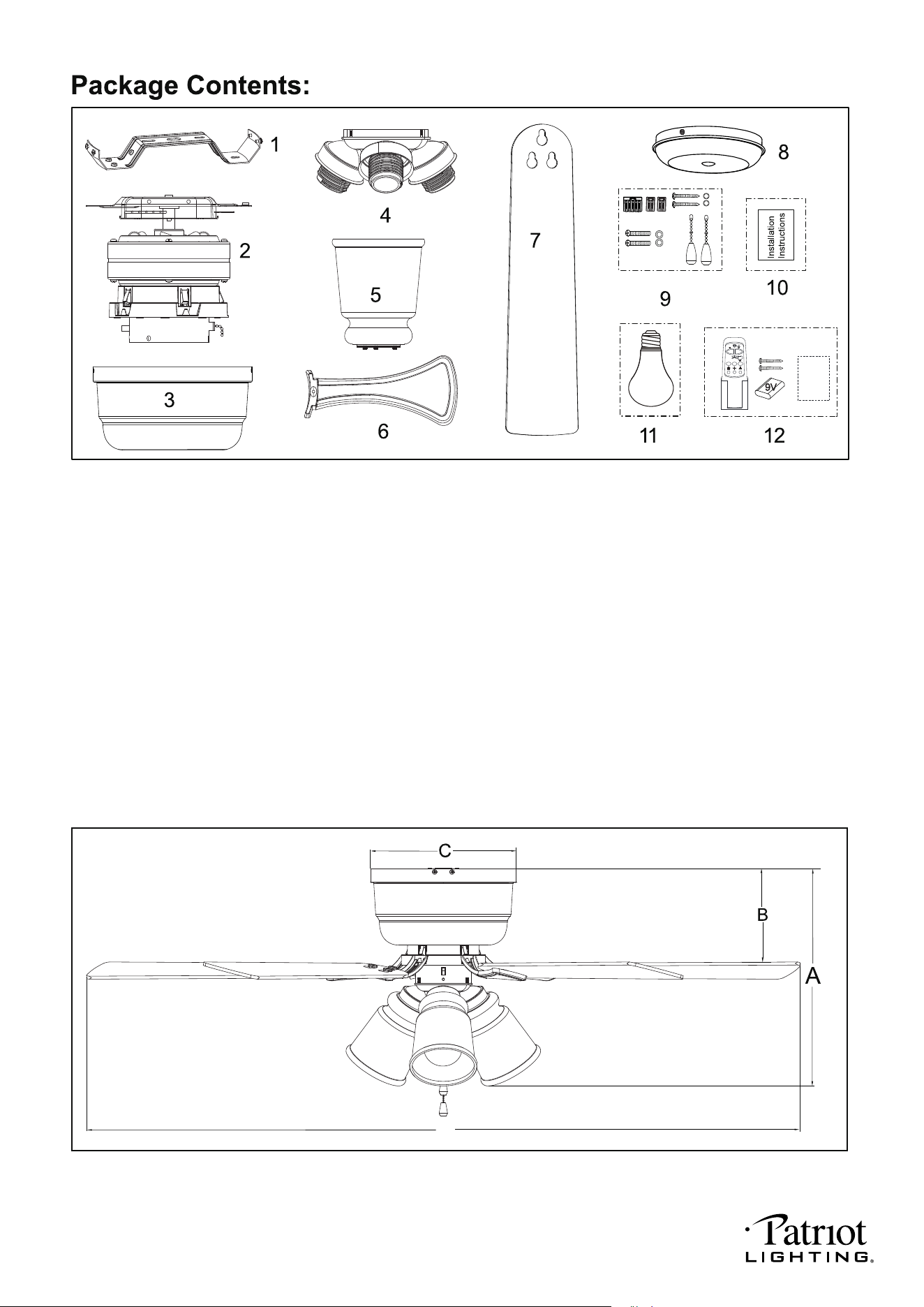
A. 15-1/8" B. 7" C. 10-1/8" D. 52"
PAGE: 2 / 9
Unpack your fan and check the contents. You should have the following items.
Dimension Reference:
D
1.) Mounting Bracket
2.) Fan Motor Assembly
3.) Housing
4.) Fan Light Kit
5.) Glass Shade (3 PCS)
6.) Blade Bracket (5 PCS)
7.) Fan Blade (5 PCS)
8.) Switch Box Cover
9.) Assembly Kit
10.) Installation Instructions
11.) 8W E26 (M) Base A19 Type LED Bulb (3 PCS)
12.) Remote Control Set (Includes Transmitter & Battery & Screws & Remote Control Instructions)
Remote
Control
Instructions
2H 4H 8H
241230
Fan Light Kit
PAGE: 3 / 9
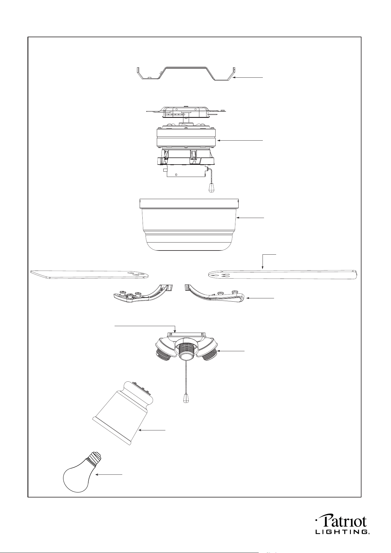
Exploded View Detail
Mounting Bracket
Fan Motor Assembly
Housing
Blade Bracket
Socket
Blade
Glass Shade
LED Bulb
241230
PAGE: 4 / 9
Safety Instructions
READ ALL SAFETY INFORMATION AND INSTALLATION INSTRUCTIONS BEFORE YOU BEGIN TO
INSTALL THE FAN AND SAVE INSTRUCTIONS.
•
All set screws of the fan must be checked and retightened where necessary before installation.
•
To reduce the risk of personal injury, do not bend the blade brackets when installing the brackets,
balancing the blades or cleaning the fan. Do not insert foreign objects between rotating fan blades.
•
Before changing the fan direction, turn off the fan and wait for the fan blades to stop completely.
•
The safeguards provided by these safety instructions and by the separate installation instructions
are not meant to cover all possible conditions and situations that may occur. It must be understood
that common sense, caution and care are factors which can not be built into this product. These
factors must be supplied by the person(s) installing, caring for and operating the fan.
WARNING
• TO AVOID RISK OF ELECTRIC SHOCK, BE SURE TO SHUT OFF POWER AT THE MAIN
FUSE OR CIRCUIT BREAKER BOX BEFORE INSTALLING OR SERVICING THIS
FIXTURE. TURNING OFF THE ELECTRICAL POWER BY USING THE LIGHT SWITCH
IS NOT SUFFICIENT TO PREVENT ELECTRICAL SHOCK.
•
TO REDUCE THE RISK OF INJURY, INSTALL THE FAN SO THAT THE BLADES ARE
AT LEAST 7 FEET (2.1 METERS) ABOVE THE FLOOR AND AT LEAST 18 INCHES
(0.5 METERS) FROM THE TIP OF THE BLADES TO THE WALL.
•
TO REDUCE THE RISK OF FIRE, ELECTRIC SHOCK, OR PERSONAL INJURY, MOUNT
TO OUTLET BOX MARKED "ACCEPTABLE FOR FAN SUPPORT" AND USE MOUNTING
SCREWS PROVIDED WITH THE OUTLET BOX.
•
THE INSTALLATION HAS TO BE IN ACCORDANCE WITH THE NATIONAL ELECTRICAL
CODE, ANSI/NFPA 70-1999 AND LOCAL CODES. IF YOU ARE UNFAMILIAR WITH THE
METHODS OF INSTALLING ELECTRICAL WIRING, SEEK THE SERVICES OF A
QUALIFIED LICENSED ELECTRICIAN.
241230
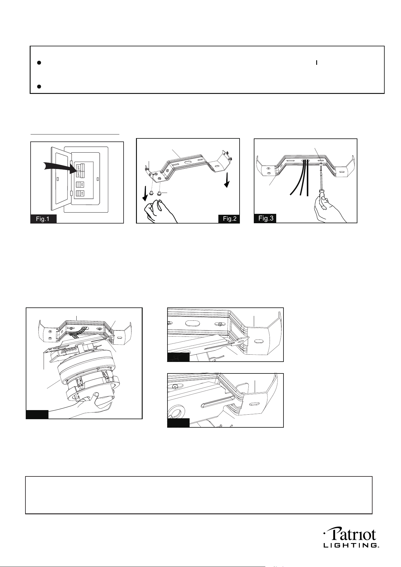
Turn OFF the electric circuit at
the main fuse or circuit breaker
box.
PAGE: 5 / 9
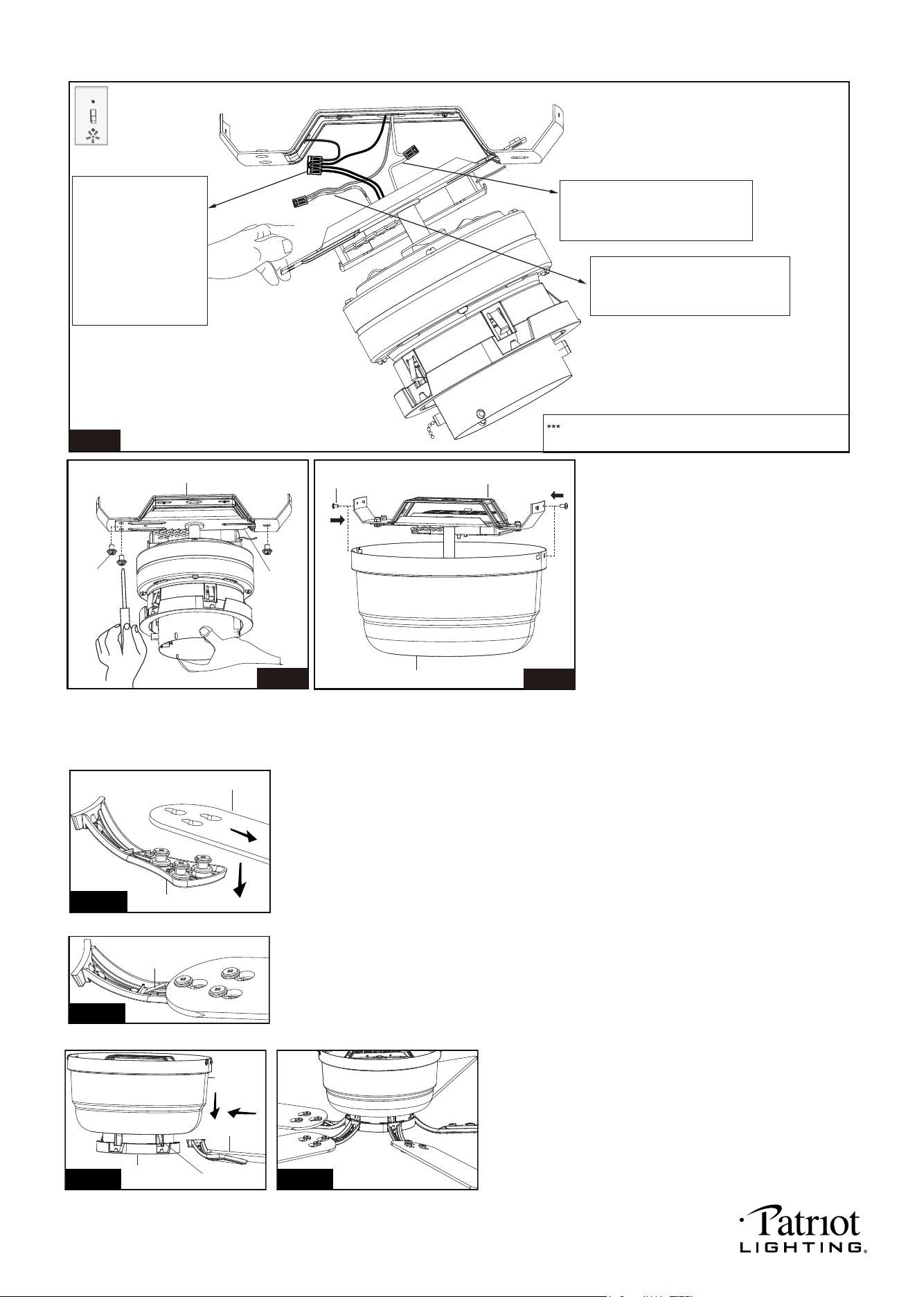
Attach the fan motor assembly onto
the mounting bracket. Insert the end A
of mounting bar through the long loop hole
of the mounting bracket for hands-free wiring.
(See Fig.4a and Fig.4b)
Note: Quick install feature: captured blade arms to motor slots and clips; turn-buckle
blades; lever wire connectors and twist-to-lock shades on the light kit. Ensure quick and
simple ceiling fan installation.
Before install
After install
Mounting Bracket
Screw
Lock Screw
Mounting Screw and Washer
Mounting
Bracket
Unscrew the two lock screws
from mounting bracket and one
lock screw from the mounting bar.
Please save lock screws and lock
washers for Fig.6 step use.
Tighten the mounting bracket to the outlet box
with two mounting screws and washers.
(To reduce the risk of fire, electric shock, or
personal injury, mount to an outlet box marked
"Acceptable for fan support" and use mounting
screws provided with the outlet box.)
Note: Pull the electrical wires from the
outlet box through the center hole of the
mounting bracket for motor wiring installation.
Long Loop
Hole
Mounting
Bar
Fan Motor
Assembly
Mounting Bracket
Fig. 4
Fig. 4a
INSTALLATION INSTRUCTIONS
NOTE: The fan weight is 16.1 lbs (7.3 kg). Be sure the outlet box you are using is securely attached to the building
structure and can support the full weight of the fan. Failure to do so can result in serious injury.
IMPORTANT:
BEFORE YOU BEGIN INSTALLING THE FAN, CAREFULLY READ ALL INFORMATION N THE SEPARATE
SHEET "SAFETY INSTRUCTIONS" AS WELL AS THE FOLLOWING "INSTALLATION INSTRUCTIONS". IF IN
DOUBT, CONSULT A QUALIFIED ELECTRICIAN.
SAVE ALL INSTRUCTIONS.
Installation Steps:
Mounting Bracket
End A
After install
Fig. 4b
Mounting Bracket
End A
End A
241230
PAGE: 6 / 9
Before install
Before install
After install
After install
Connect the white (neutral) wire
from receiver to the white (neutral)
wire from the outlet box with a 2
pin lever wire connector.
Connect the four ground
wires (green or bare
copper) using a 5 pin
lever wire connector.
One ground (green or
bare copper) wire will
come from outlet box
and the other three
ground (green) wires
come from the fan.
The wire connection points should be turned upward
and pushed carefully up into outlet box.
Connect the black (hot) wire from
receiver to the black (hot) wire from
outlet box with a 2 pin lever wire
connector.
Fig. 5
For a single switch
Follow these steps:
Attach the mounting bar to the mounting
bracket using the three lock screws.
Then free your hands to secure the lock
screws using a Philips screwdriver.
Fasten the blade brackets to the motor.
Align and engage the blade bracket to the metal spring of
fan-motor assembly and then insert the blade bracket into
the slot of the blade bracket ring until the blade engages in
the locking mechanism. Make sure the locking mechanism
at the bottom side of the motor springs upward and butts
against the edge of the blade bracket indicating a secure
connection. Repeat this step for the remaining blade brackets
assemblies.
Attach the blades to the blade brackets.
● Mount the fan blades to the blade brackets by aligning the three key-slot holes in the blade
with the three posts on the top of the blade bracket.
● Hold the blade close to the blade bracket and press the blade down firmly. Ensure
key-slot holes are properly seated on the blade bracket posts.
● While still holding the blade down, firmly slide the blade away from the bracket side until
the blade engages in the locking mechanism. Make sure the locking mechanism at the rear
of the blade bracket springs upward and butts against the edge of the blade indicating a
secure connection.
● Repeat for the remaining blades.
There are four mounting bracket screws.
Remove two screws from the mounting
bracket (one from each side) and loosen
the other two remaining screws. Align the
"L shaped" slots of the housing with the
two remaining screws on the mounting
bracket. Push the housing upwards to
engage the slots and turn clockwise to lock
in place. Tighten the screws and install the
other two mounting bracket screws, which
were previously removed, into the remaining
holes of the housing and tighten.
Lock
Screw
Mounting Bracket
Mounting
Bar
Fig.6
Mounting Bracket
Screw
Housing
Fig.7
Blade Bracket
Blade
Fig.8a
Fig.8b
Spring
Blade Bracket
Spring
Blade
Bracket Ring
Housing
Fig.9a Fig.9b
241230
PAGE: 7 / 9
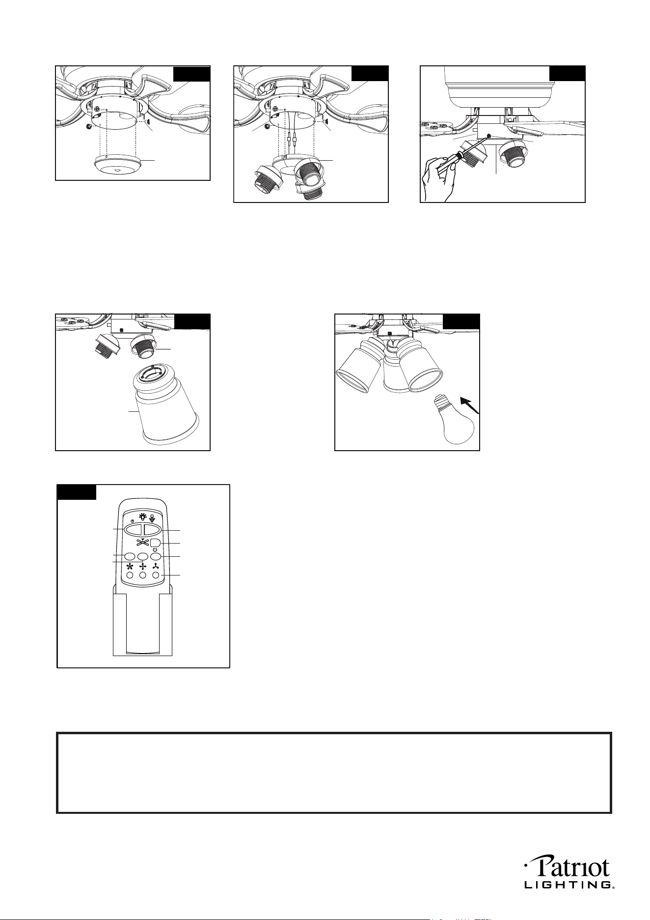
Install LED bulbs (included).
See relamping label at socket
area or packaging for
maximum wattage allowed.
Unscrew the three switch box cover
screws from the fan light kit, then
connect the white (neutral) wire from
the fan motor assembly to white
(neutral) wire from fan light kit with a
pin connector, connect the blue (hot)
wire from fan light to the blue (hot) wire
from fan motor assembly with a pin connector.
Install without fan light Install fan light
Switch Box
Cover
Switch Box
Cover Screw
Fig.10
Fan Light Kit
Switch Box
Cover Screw
Fig.11
Fan Motor
Assembly
Attach the glass shade
onto the socket, then rotate
it clockwise carefully until it
is locked in place. Repeat
for the remaining glass
shades.
Fig.13
Socket
Glass
Shade
3-8W A19 LED
Bulbs (included)
E26 A19 bulb Max. 60W
Fig.14
Switch Box
Cover Screw
Fig.12
Fan Light Kit
Install the fan light kit onto the switch box
with the three switch box cover screws
attached to the fan light kit.
Fan Motor
Assembly
Unscrew the three switch box cover
screws from the switch box cover.
Secure the switch box cover into
switch box with the switch box cover
screws.
To install the fan light, skip this
step and proceed to Fig.11.
Fig.15
HI
MED
LIGHT ON/OFF
DIMMER
FAN OFF
LOW
TIMER
2H 4H 8H
* Press "HI" button to turn on the fan at high speed.
* Press "MED" button to turn the fan in medium speed.
* Press "LOW" button to turn the fan in low speed.
* Press "FAN OFF" button to turn off the fan.
Operating transmitter:
Install the battery (9V, included) into the transmitter.
The remote buttons function as below.
* Press "LIGHT ON /OFF" button to turn on or turn off the light.
* Press and hold the "DIMMER" button to dim or brighten lights to the desired level and
release, and the brightness level will be memorized. Turn on the light again, then fan
light will be restored to the brightness-level at which it was dimmed last time.
* Timer Control:
Press "2H","4H" or "8H" "Timer" button can be set to automatically turn off the fan and
the light. If the light is off and the fan in on, the timer can automatically turn the fan off
in the selected timer time. (Same goes for the light.)
Press light off or fan off button to stop the timer control and the light or fan will turn
off at the same time.
Note:
This remote control has a memory function setting. The fan will operate at the same speed and the fan light will stay
at the same brightness-level as the last time the power supply was turned off.
Set the code:
Within the 10 second time frame after the main power is turned on, press and hold FAN OFF button for more than 3 seconds.
The LED light will begin to flash. Once the code is set successfully, the fan will turn off and the light will turn on.
Note: The included transmitter was paired with the receiver at the factory with default settings, so no need to set
the code again. Go through these setup steps if you found your transmitter can’t communicate with the
receiver.
241230
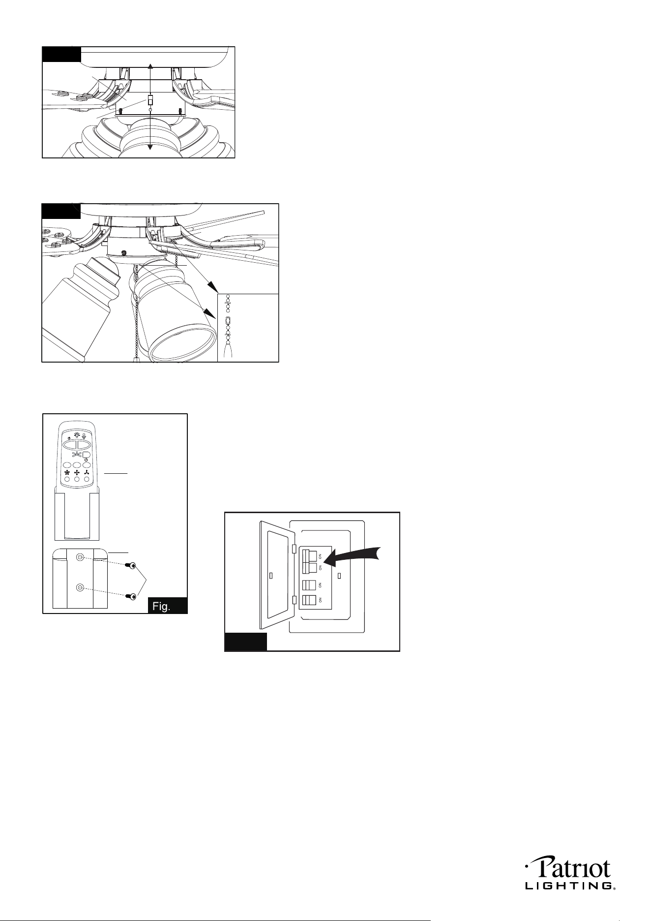
Fig. 19
Turn ON the electric power at the
main fuse or circuit breaker box.
PAGE: 8 / 9
Install the transmitter wall bracket
on the wall with two screws
and place transmitter in it carefully.
Transmitter
Wall Bracket
Screw
18
2H 4H 8H
Fig.16
Slide Switch
Forward
Switch Box
Reverse
Fig.17
Fan Light Switch
Install pull
chains
and drops
Fan Switch
The slide switch on switch box sets direction of fan rotation . Select the desired
direction of fan rotation.
Push the slide switch down for "Forward" and up for "Reverse".
Note : Wait for fan to stop before reversing the direction of blade rotation .
Install two pull chains and drops onto the pull chains located in the switch box
and light kit.
The pull chain controls the fan speed as follows:
1 pull - High, 2 pull - Medium, 3 pull - Low and 4 pull - Off.
To turn the light kit " ON " or " OFF ", pull the chain that is attached to the light kit .
CAUTION: Before operating the remote control, make sure to use the
pull chain to select the "high" position for the fan speed
and the "on" position for the fan light.
241230

CAUTION: Make sure main power is turned off.
CAUTION: Make sure main power is turned off before entering switch box.
CAUTION: Make sure main circuit is turned off before entering switch box.
Troubleshooting Guide
PROBLEM
PAGE: 9 / 9
If you have diftficulty operating your new ceiling fan, it may be the result of incorrect assembly, installation
or wiring. lf you experience any faults, please check this Troubleshooting Guide.lf a problem cannot be
remedied or you are experiencing dificulty in installation, please call our Customer Service Department
(1-800-887-6326).
SUGGESTED REMEDY
1. lf fan does not start:
1.Check main and branch circuit fuses or circuit breakers.
2. Make sure forward/reverse switch is firmly in bottom or top position. Fan will not
operate when switch is in the middle.
3. Make sure that the wall control is turned "ON".
4. Check line wire connections to fan and switch wire connections in switch box.
1. Make sure all screws in motor housing are snug. (not too tight)
2. Make sure the screws which attach the fan blade bracket to the motor are tight.
3. Make sure wire connectors in switch box are not rattling against each
other or against the interior wall of the switch box.
2. lf fan sounds noisy:
4. lf using an optional ceiling fan light kit, make sure the screws securing
the glassware are finger tight. Make sure light bulb is tight in socket and
not touching glass shade(s). lf vibration persists from glass, remove glass and
install a 1/4 in. wide rubber band on glass neck to act as an insulator. Replace
glass and tighten screws against rubber band.
5. Some fan motors are sensitive to signals from Solid State variable speed
controls. DO NOT USE a Solid State variable speed control.
6. Allow "break-in" period of 24 hours. Most noises associated with a new fan will
disappear after this period.
3. lf fan wobbles:
All blades are weighed and grouped by weight. Natural woods vary in density
which could cause the fan to wobble even though all blades are weight-matched.
The following procedures should eliminate most of the wobble. Check for wobble
after each step.
1. Check that all blades are screwed firmly into blade brackets.
2. Check that all blade brackets are tightened securely to motor.
3. Make sure that canopy and mounting plate are tightened securely to ceiling
junction box and junction box is mounted firmly to ceiling joist.
4. Most wobble problems of fan are caused when blades are not in equal level. To
check the blade levels, select a point on the ceiling above the tip of any blade.
Measure the distance from the ceiling to the blade tip, to an accuracy of 1/8
inch. Rotate the blades until the next blade is in the measuring position. Repeat
measurement for each blade. lf all blade levels are not equal, you can adjust
blade levels by the following procedure. To adjust a blade tip down, insert a
washer (not supplied) between the blade and blade bracket at the screw
closest to the motor. To adjust a blade tip up, insert washer (not supplied)
between the blade and blade bracket at the two screws farthest from the motor.
5. Interchanging two adjacent blades could redistribute the weight and possibly result
in smoother operation.
4. lf light does not work:
1. Check blue wire from fan to make sure it is connected to hot wire from supply wire
coming out of the ceiling.
2. Check for loose or disconnected wires in fan switch box.
3. Check for loose or disconnected wires in light kit.
4. Check for faulty light bulbs.
241230
