SKU Number: 356-1290
356-1
291
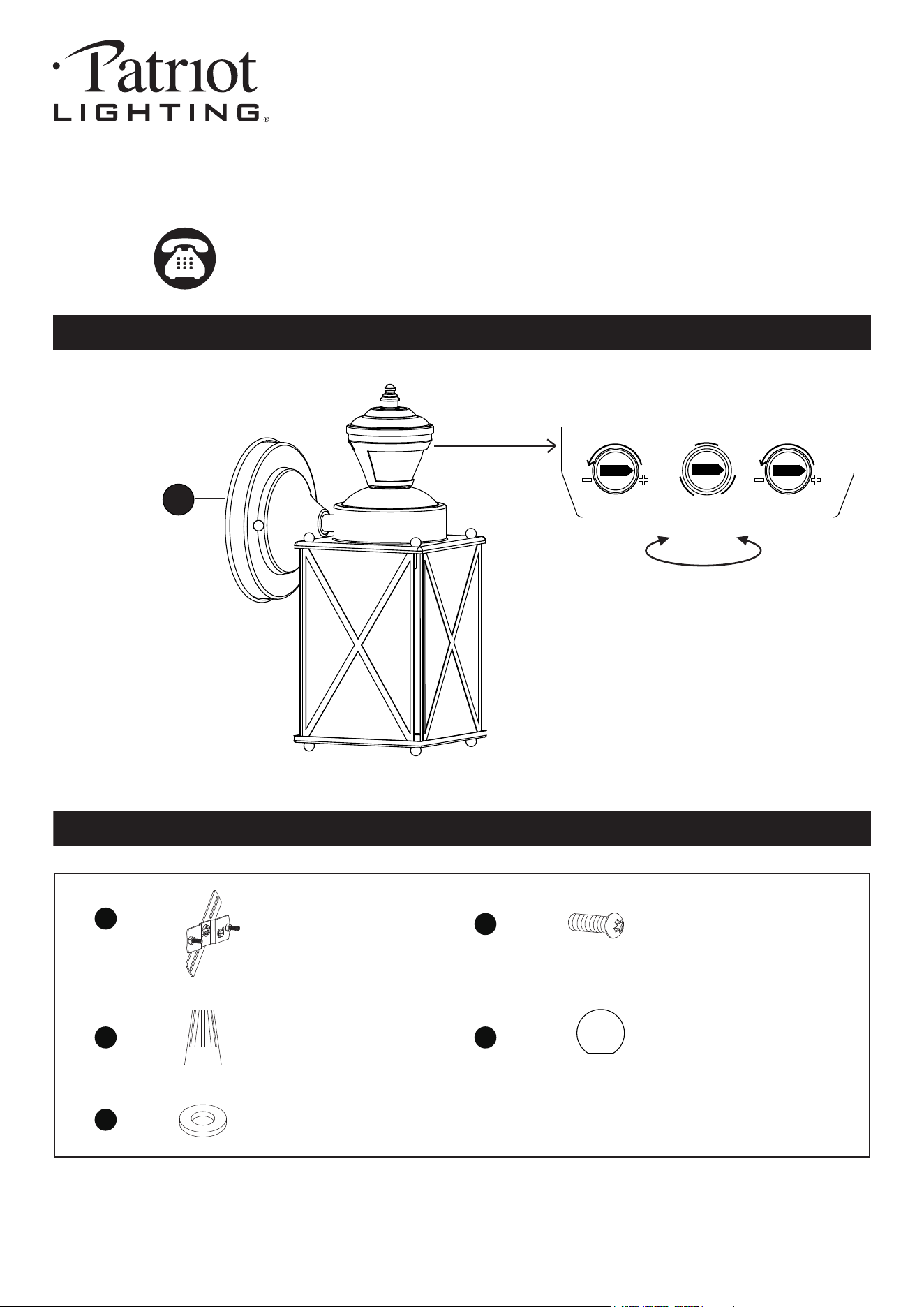
PACKAGE CONTENTS
Questions, problems, missing parts?
Before returning to your retailer, call our customer service at 1-800-887-6326
Monday – Friday 9:00 a.m. – 5:00 p.m. CST
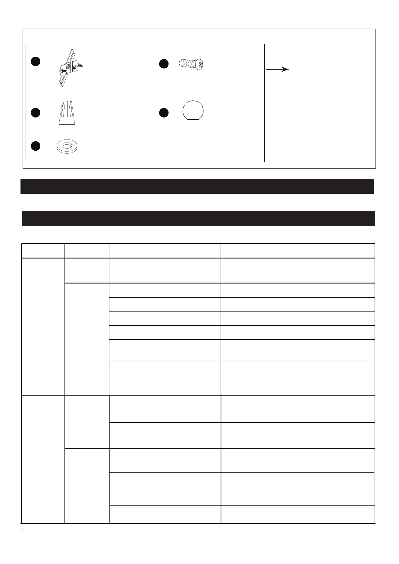
HARDWARE CONTENTS Note: Hardware not shown actual size.
Model Number: DJ2266 MBLK
DJ2267 STNSLVR
250218
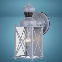
1-Light Outdoor Motion Sensing Wall Lantern
Crossbar Unit
X1
Mounting Screw
X2
Wire Connector
X3
Bolt Nut
X2
Rubber Pad
X2
AA
BB
CC
DD
EE
Rotate to access EZSET sensor settings
TM
Time Mode Sens
Auto
Test
PC
A
Page 2 of 6
250218
Before beginning assembly, installation or operation of product, make sure all parts are present. Compare parts with
package contents list and diagram on previous page. If any part is missing or damaged, do not attempt to assemble,
install or operate the product. Contact customer service for replacement parts.
Tools Required for Assembly (not included): Slotted Screwdriver, Phillips Screwdriver, Pliers, Electrical Tape, Wire
Cutters, Safety Glasses, Ladder, Wire Stripper, Silicone Caulk.
PREPARATION
ASSEMBLY INSTRUCTIONS
SAFETY INFORMATION
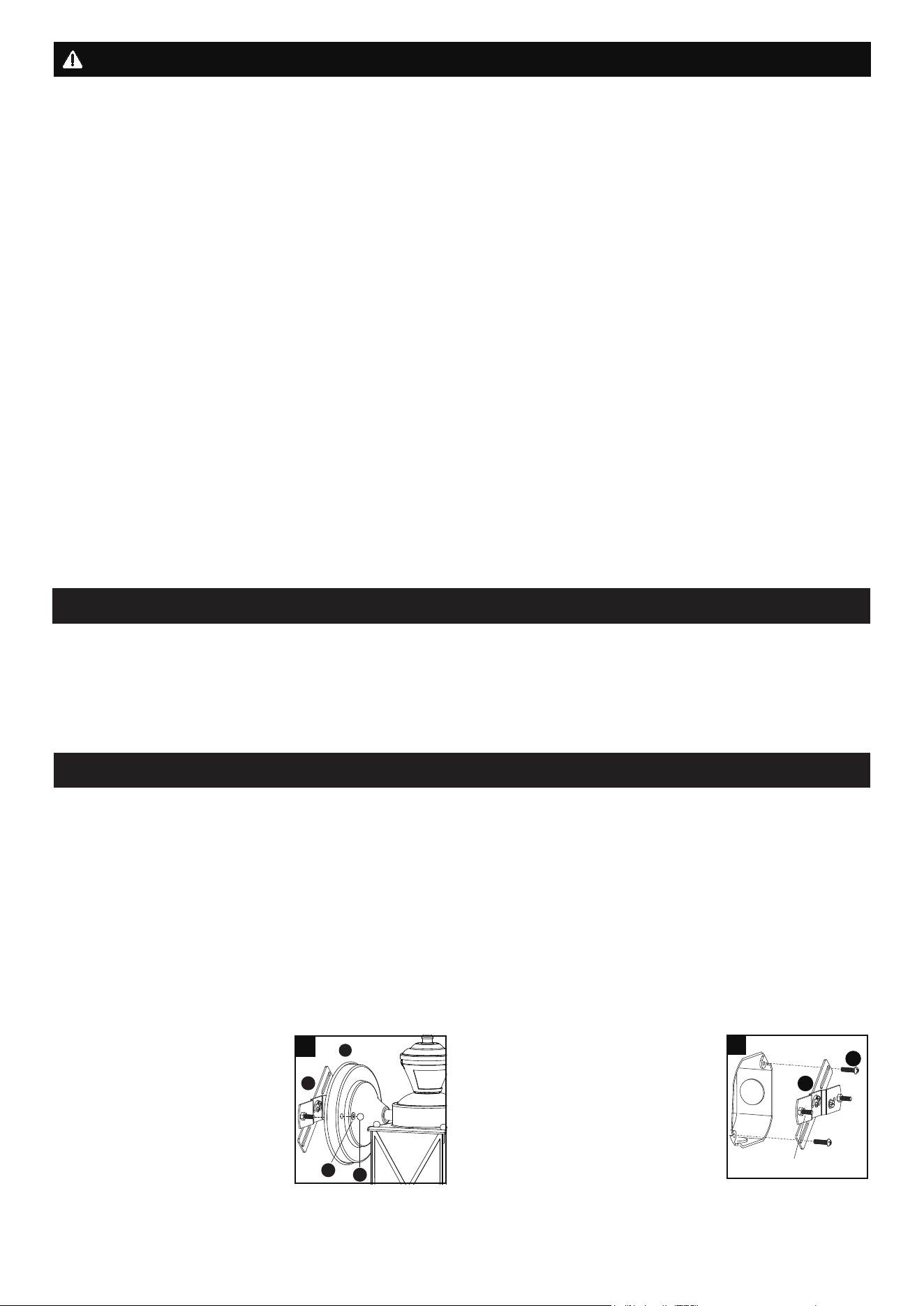
1. Unscrew the two bolt nuts (DD)
Remove the two rubber pads
(EE) and the crossbar unit (AA)
from the backplate (A).
.
Please read and understand this entire manual before attempting to assemble, operate or install the product.
WARNING
● Turn off electricity at main fuse box (or circuit breaker box) before beginning installation by removing fuse (or
switching off circuit breaker).
● Be careful not to damage or cut the wire insulation (covering) during fixture installation. Do not permit wires to contact
any surface having a sharp edge. To do so may damage or cut the wire insulation, which could cause serious injury
or death from electric shock.
CAUTION
● All electrical connections must be in agreement with local codes, ordinances or the national electric code (NEC).
Contact your municipal building department to learn about your local codes, permits and/or inspections.
● Risk of fire – most dwellings built before 1985 have supply wire rated for 140°F/60ºC. Consult a qualified electrician
before installation.
● Do not connect this fixture to an electrical system that does not provide a means for equipment grounding. Never use
a fixture in a two-wire system that is not grounded. If you are not sure your lighting system has a grounding means,
do not attempt to install this fixture. Contact a qualified, licensed electrician for information with regards to proper
grounding methods as required by the local electrical code in your area.
● Only a general ON/OFF wall switch applies for this fixture, a dimmable wall switch shouldn’t be used.
Installation Steps
Turn off the power at fuse or circuit box.
A
AA
DD
EE
1
Maximum Wattage: 60W
Work Temperature: - 22°F~104°F
Important to know
2. Attach the crossbar unit (AA) to
the outlet box by using two
mounting screws (BB). Adjust the
length of the preinstalled fixture
mounting screws if necessary.
Note: Make sure that the fixture
mounting screws are lined up
horizontally to make the fixture
level.
AA
BB
2
Fixture Mounting Screw
1. This fixture requires a 120VAC, 60Hz power source.
2. Make sure the power is switched OFF before installation.
3. Motion sensor: turns light ON automatically when motion is detected and turns light OFF automatically when motion
stops.
4. Photocell keeps the light OFF during the daytime.
5. Compatible with both dimmable and non-dimmable LED bulbs.
Page 3 of 6
ASSEMBLY INSTRUCTIONS (continued)
The Position of Control Panel
Sensor
250218
Turn on the power at fuse or circuit box.
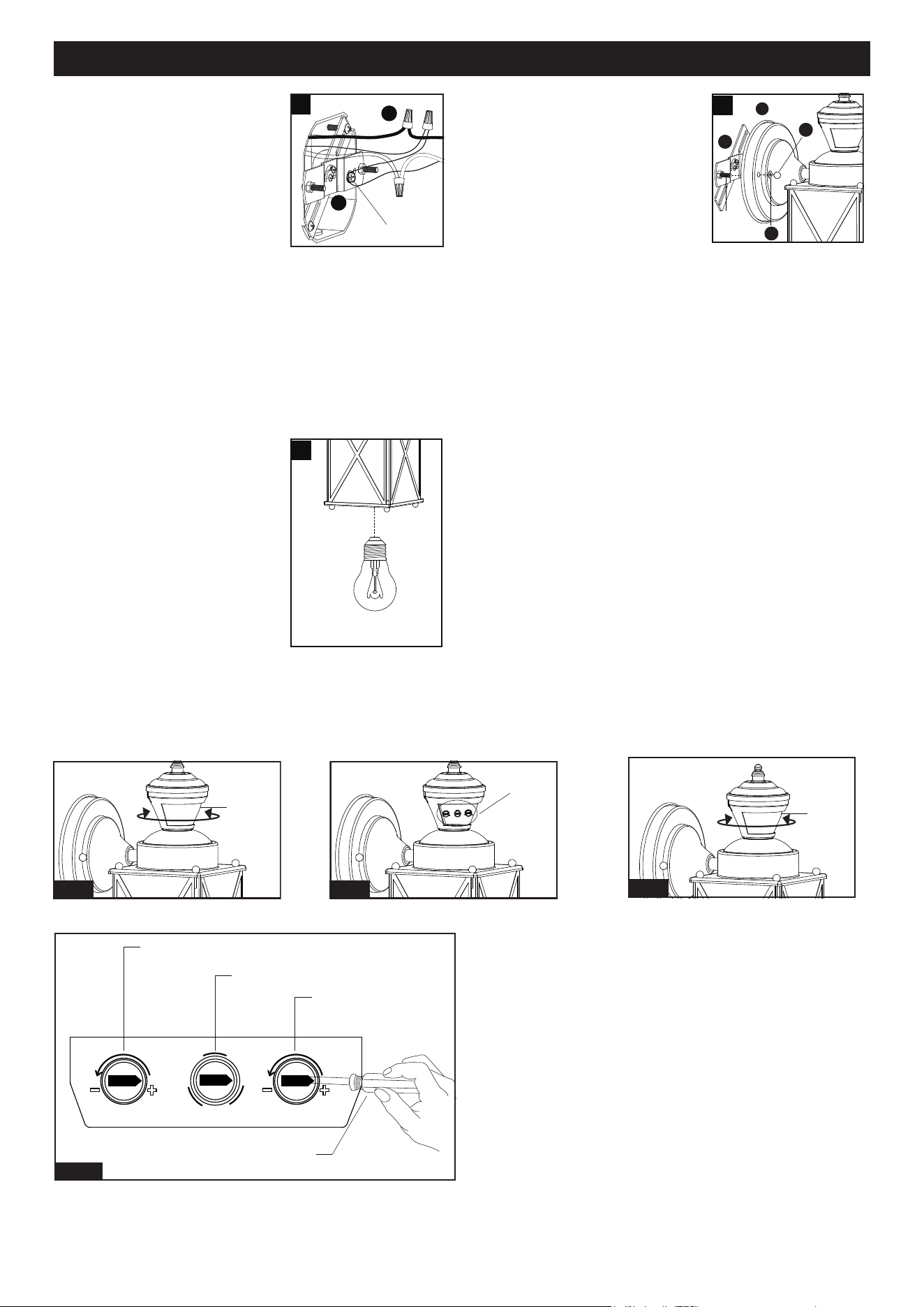
5. Install the bulb (not included).
See relamping label at socket
area or packaging for
maximum wattage allowed.
3. Pull out the source wires from
the outlet box. Make wire
connections using wire
connectors (CC) as follows:
• Connect the hot wire (black
insulation) from the fixture to
the black wire from the power
source.
• Connect the neutral wire
(white insulation) from the fixture to the white wire
from the power source.
• Attach the fixture ground wire (bare wire) to the
crossbar unit (AA) with the green ground screw,
then depending on local code, connect it to the
house ground wire with the wire connector (CC).
Carefully put all of the wires back into the outlet box.
3
Green Ground Screw
CC
AA
4. Attach the backplate (A) of the
fixture to the crossbar unit (AA) by
aligning and inserting the two
fixture mounting screws from the
crossbar unit (AA) into the open
holes on the backplate (A), then
place the two rubber pads (EE)
over the exposed fixture mounting
screws before screwing the two
bolt nuts (DD) on to screws.
Note: With silicone caulk compound, caulk
completely around where the backplate meets with
the wall surface to prevent water from seeping into
the outlet box.
A
AA
DD
EE
4
Max.60W Type A Bulb
(not included)
5
Sensor
Fig.1 Fig.2
View Fig.A
Fig.3
Step 1: Rotate the sensor clockwise or counter-clockwise
at maximum 90 degree to show the adjustable
knobs. (See Fig.1)
Step 2: Adjust time and sensitivity, choose the mode you
want by turning the knob. (See Fig.2 and Fig.A).
Step 3: Restore the sensor to original position by rotating
to the opposite direction. (See Fig.3)
Fig.A
"Time" Knob
"Mode" Knob
"Sens" Knob
Small Screwdriver
(not included)
Fig.A
Time Mode Sens
Auto
Test
PC
Fixture
Mounting
Screw
Page 4 of 6
FUNCTIONS AND OPERATIONS
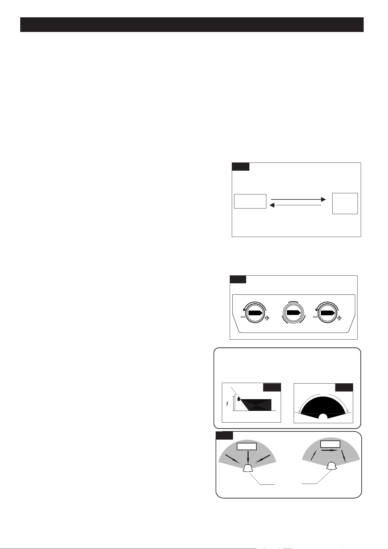
Where you install your lantern is important:
Be sure the light is mounted straight on the wall;
otherwise, the detection distance may be limited.
5`
6`
10`
30`
Fig.6
Fig. 7
Least sensitivity
Most sensitivity
Sensor
Fig. 8
Motion
Motion
NOTE:
1. The sensitivity of the motion sensor will increase as the
environmental temperature gets colder. For best performance,
gently clean the lens with a soft cloth every 1 or 2 months to
ensure maximum sensitivity.
2.
When installed at a height of 6.5 feet, at 77 degrees Fahrenheit,
the light will provide a maximum detection distance of 30 feet
and detection range of 150 degrees. (See Fig.6 Fig.7)
3. The sensor will be more sensitive to motion across its
detection path than motion directly towards it. (See Fig.8)
4. To reduce possible nuisances, do not mount the fixture
near a heat source like an air conditioner, vent or furnace
exhaust, or in a direction facing any reflecting object or
other light source.
Choose a mode by turning the rotary knob. The light will turn on immediately when power is applied. Wait for 30
seconds to allow the sensor to warm up.
1. Test MODE (daytime and nighttime operation.)
● The light will turn on when motion is detected, and stay on as long as the motion continues. The light will turn off
after 5 seconds when motion is no longer detected.
2. Auto MODE (nighttime operation only)
● At dusk, the light will turn on when motion is detected, and stay on as long as the motion continues. When the
motion stops, the light will remain on for the predetermined time set (5~180 seconds) and then turn off.
● The light will turn off automatically at dawn.
3. PC MODE (nighttime operation only)
● The light will turn on automatically at dusk and turn off automatically at dawn.
Customization Options
Shut-off Delay
Fig. 5
(View from back of sensor lens)
1. The Shut-off delay is the length of time that the light will stay on
after motion stops.
2. The Shut-off delay can be adjusted by using the "Time" knob when
the knob is set in "Auto" mode.
3. The range of shut-off delay is 5 seconds to 3 minutes.
4. Rotate the knob clockwise for increasing the shut-off delay.
5. Rotate the knob counterclockwise for decreasing the shut-off delay.
Sensitivity of Motion Sensor
1. The sensitivity can be adjusted from 5 to 30 feet by using the
"Sens" knob. (See Fig.5).
2. Turn the knob clockwise for increased sensitivity.
3. Turn the knob counterclockwise for decreased sensitivity.
Auto Mode
Manual
Override
Manual Override Operation Diagram
Turn wall switch OFF-ON
in 0.5~3 Seconds
Turn wall switch OFF-ON
in 0.5~3 Seconds
Fig. 4
4. Manual Override MODE (nighttime operation only)
● To shift to the manual override mode, set the switch to "Auto" mode.
Turn the wall switch "OFF" and then turn it "ON" within 3 seconds.
The light will stay on through all night. To restore to the "Auto" mode,
turn the wall switch "OFF" and then turn it "ON" within 3 seconds
again. (See Fig.4)
● The light will last for one night only and turn off automatically at
dawn.
Note: 1. Always keep the wall switch in the "ON" position
(including the daytime).
2. Please notice the warm up time is 30 seconds, any
operations are invalid during this time.
150˚
250218
Time Mode Sens
Auto
Test
PC
Page 5 of 6Page 5 of 6
● To clean, turn off and wipe with a damp, non-abrasive cloth.
CARE AND MAINTENANCE
The following parts are available for reorder if damaged or missing. Call our toll-free at 1-800-887-6326.
Assembly Kit
6567MM (1 SET) FOR 356-1290
6568MM (1 SET) FOR 356-1291
Spare Parts List:
TROUBLESHOOTING
Refer to following information to solve your problems.
250218
Crossbar Unit
X1
Mounting Screw
X2
Wire Connector
X3
Bolt Nut
X2
Rubber Pad
X2
AA
BB
CC DD
EE
Set the rotary knob in the test mode for testing.
Night
If the light
isn’t on
SYMPTOM
DAY/NIGHT
POSSIBLE CAUSE
SOLUTION
Day
Rotary knob is not set in the test
mode.
Wall switch or circuit breaker is off. Turn on wall switch or circuit breaker.
Test the light bulb on normal working light fixture.
Tighten the light bulb.
Check wire connections.
Relocate fixture away from western facing wall.
Eliminate or turn off other light source, block other
light source from shining onto sensor, or relocate
fixture.
Light bulb may be burned out.
Light bulb is loose.
Incorrect or loose wire connections.
Too much sunlight is shining onto
sensor in the early evening.
Too much light is shining onto
sensor due to another light source,
such as a street lamp or other light
fixture.
The fixture may be installed in
shaded area.
Only need to relocate fixture.
No corrective action needed.
On cloudy or overcast days, the light
may stay on longer than anticipated.
Still on the manual override mode. Turn off the light, then turn it on after 5 seconds.
False triggering caused by a heat
source, such as a heater, dryer vent,
or heated swimming pool.
Eliminate heat source or relocate fixture.
The knob is not set in any mode.
Rotate it again to the mode you want.
Day
Night
If the light
stays on
Page 6 of 6
250218
TROUBLESHOOTING (continued)
If unable to fix any of the above issues, please consult a certified electrician.
FIVE-YEAR LIMITED WARRANTY: If, during normal use, this PATRIOT LIGHTING lighting fixture breaks or fails
due to a defect in material workmanship within five (5) years from the date of original purchase, simply bring this
lighting fixture with the original sales receipt back to your nearest MENARDS retail store. At its discretion, PATRIOT
LIGHTING agrees to have the product or any defective part(s) repaired or replaced with the same or similar PATRIOT
LIGHTING product or part free of charge, within the stated warranty period, when returned by the original purchaser
with original sales receipt. This warranty; (1) excludes expendable parts including but not limited to light bulbs; (2) does
not cover damage that has resulted from abuse or misuse; and (3) does not cover any losses, labor, injuries to
persons/property or costs. This warranty does give you specific legal rights and you may have other rights, which vary
from state to state.
R
R
R
R
Questions, problems, missing parts?
Before returning to your retailer, call our customer service at 1-800-887-6326
Monday – Friday 9:00 a.m. – 5:00 p.m. CST
The light
comes on for
no apparent
reason
If the light
is blinking
Night
Night
False triggering caused by a heat
source, such as a heater, dryer vent,
or heated swimming pool.
Eliminate heat source or relocate fixture.
SYMPTOM
DAY/NIGHT
POSSIBLE CAUSE
SOLUTION
Passing cars and reflective objects
interfere with the sensor.
Relocate fixture.
Street or sidewalk traffic is triggering
motion sensor.
Adjust the "Sens" knob to reduce the sensitivity.