Questions, problems, missing parts?
Before returning to your retailer, call our customer service at 1-800-887-6326
Monday – Friday 9:00 a.m. – 5:00 p.m. CST
Sku Number: 356-3836
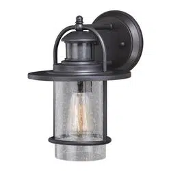
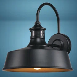
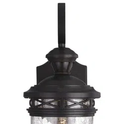
OUTDOOR SENSOR LIGHT
Model Number:DH8096
Page 1 of 6
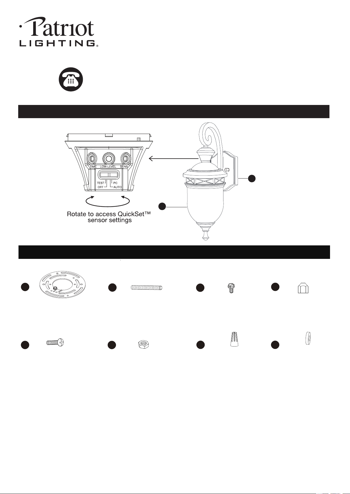
A
B
HARDWARE CONTENTS Note: Hardware not shown actual size.
AA
BB
DD
EE
FF
GG
CC
Mounting Screw
X2
Green Grounding
Screw X1
Lock Nut
X4
Wire Connector
X3
HH
Rubber Pad
X2
Ball Nut
X2
Mounting Plate
X1
Headless Screw
X2
PACKAGE CONTENTS
Before beginning assembly, installation or operation of product, make sure all parts are present. Compare parts with
package contents list and diagram on previous page. If any part is missing or damaged, do not attempt to assemble,
install or operate the product. Contact customer service for replacement parts.
Tools Required for Assembly (not included): Screwdriver, Phillips Screwdriver, Pliers, Electrical Tape, Wire Cutters,
Safety Glasses, Ladder.
Page 2 of 6
SAFETY INFORMATION
PREPARATION
Installation Steps
Important to know
ASSEMBLY INSTRUCTIONS
1. This fixture requires a 120 VAC, 60 Hz power source.
2. For general safety and to avoid any possible damage to the sensor, be sure the power is switched "off" before
adjustment.
3. Motion sensor: turns light ON automatically when motion is detected and turns light OFF automatically when motion
stops.
4. Photocell keeps the light OFF during daylight hours.
5. Compatible with LED dimmable bulb.
6. Use the dim-to-bright illumination option where you want some minimum illumination through out the night, such as
at your front entrance or garage door. Use the dark-to-bright illumination option where you do not need minimum
brightness, such as the backyard or back porch.
• All electrical connections must be in agreement with local codes, ordinances or the national electric code (NEC).
Contact your municipal building department to learn about your local codes, permits and/or inspections.
• Risk of fire – most dwellings built before 1985 have supply wire rated for 140°F/60ºC. Consult a qualified electrician
before installation
• Do not connect this fixture to an electrical system that does not provide a means for equipment grounding. Never use
a fixture in a two-wire system that is not grounded. If you are not sure your lighting system has a grounding means, do
not attempt to install this fixture. Contact a qualified, licensed electrician for information with regards to proper
grounding methods as required by the local electrical code in your area.
• Only general ON/OFF wall switch applies for this fixture, the dimmable wall switch shouldn’t be required.
Please read and understand this entire manual before attempting to assemble, operate or install the product.
WARNING
•
Turn off electricity at main fuse box (or circuit breaker box) before beginning installation by removing fuse (or switching
off circuit breaker).
• Be careful not to damage or cut the wire insulation (covering) during fixture installation. Do not permit wires to contact
any surface having a sharp edge. To do so may damage or cut the wire insulation, which could cause serious injury
or death from electric shock.
CAUTION
Maximum Wattage: 60W
Work Temperature: - 4°F~104°F
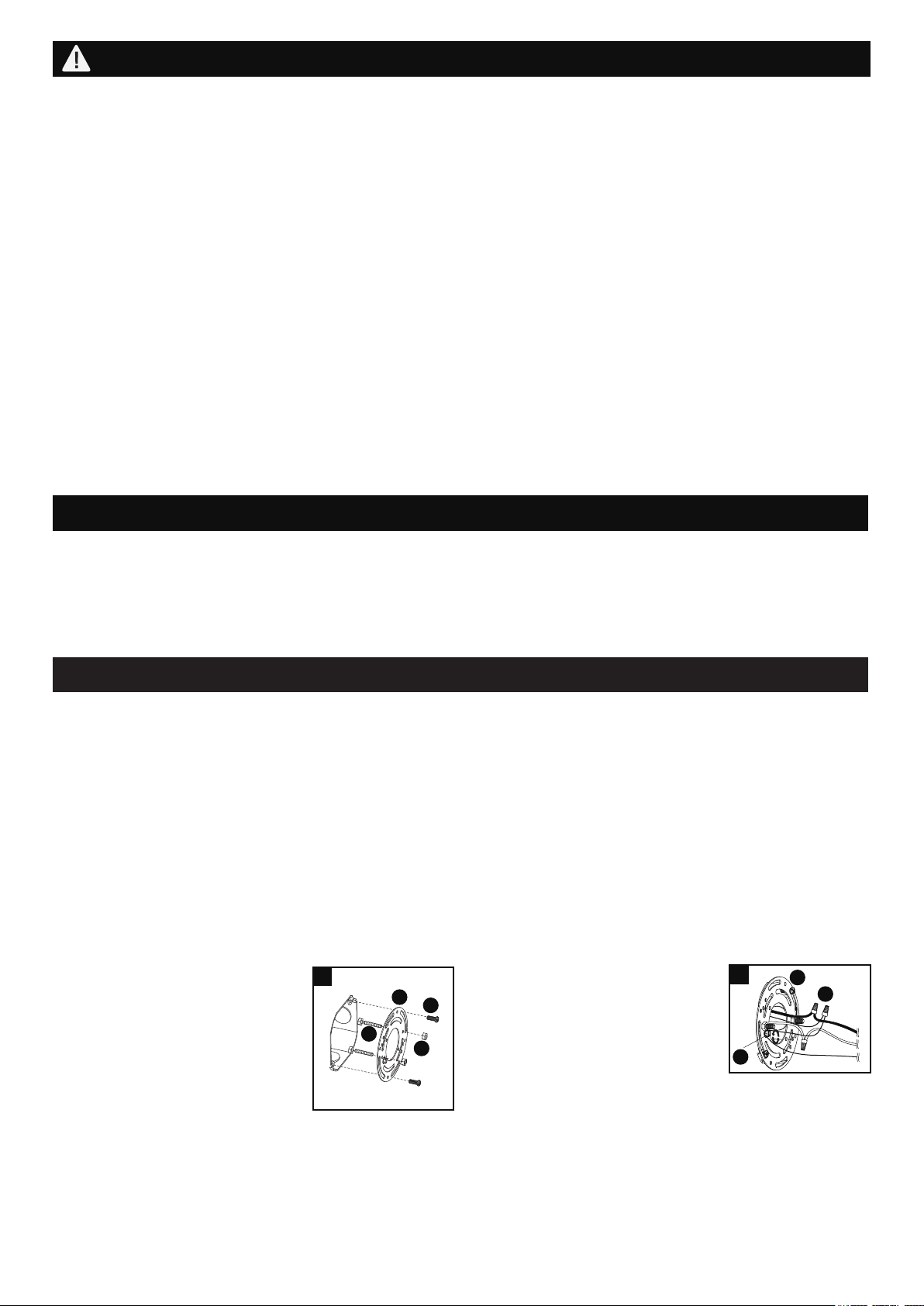
1. Thread two headless screws(CC)
through the mounting plate(AA),
and then secure them with four
lock nuts(DD) (two on each side of
the mounting plate(AA)). Adjust the
length of the headless screws(CC)
if necessary.
Note: Make sure that the
headless screws are lined up
horizontally to make the fixture level.
Attach mounting plate(AA) to the outlet box using two
mounting screws(BB).
1
AA
BB
DD
CC
2. Pull out the source wires from the
outlet box. Make wire connections
using wire connectors (FF) as
follows:
• Connect the hot wire (usually
black insulation) from the fixture
to the black wire from the power source.
• Connect the neutral wire (usually white insulation)
from the fixture to the white wire from the power
source.
• Attach the fixture grounding wire (usually green
insulation or bare wire) to the mounting plate (AA) with
the green grounding screw (EE), and then connect it to
the house grounding wire with the wire connector (FF).
Carefully put all of the wires back into the outlet box.
FF
AA
2
EE
Turn off the power at fuse or circuit box.
Page 3 of 6
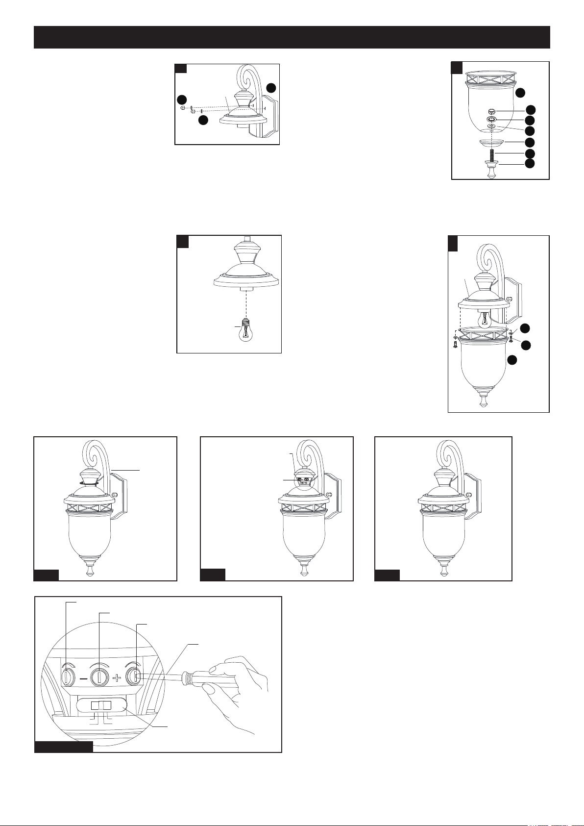
ASSEMBLY INSTRUCTIONS (continued)
Step 1: Rotate the sensor lens counterclockwise to show
up the adjustable knobs and slide switch.
(See Fig.1)
Step 2: Use the small flathead screwdriver to adjust time,
low level brightness and sensitivity. And slide the
slide switch to choose desired mode. (See Fig.2
and Detail A view).
Step 3: Rotate the sensor lens clockwise to restore original
position.(See Fig.3)
“TIME” Knob
“LOW LEVEL” Knob
“SENS” Knob
Flathead Screwdriver
(not included)
Slide Switch
TEST
OFF
AUTO
PC
TIME
LOW LEVEL
SENS
Detail A View
LEVEL Adjustable
Knob
The Position of Adjustable Knob
Sensor
Lens
See Detail A
Fig.1
Fig.2
Fig.3
4. Attach the back plate (A) to
the mounting plate (AA) by
inserting headless screws
(CC) into holes on back plate
(A), and then secure them
with two rubber pads (HH)
and two ball nuts (GG).
CAUTION:With silicone
caulking compound, caulk
completely around where
the back plate meets with
the wall surface to prevent
water from seeping into the outlet box.
5
5. Install a bulb (not included).
See relamping label at socket
area or packaging for
maximum allowed wattage.
6. Use the threaded pipe (JJ)
through the decorated cup
(LL) , glass (B), rubber pad
(OO) and washer (KK), then
turn the hex nut (II) to fix them.
7. Remove the rubber pads and
set screws from the fixture,
then attach the glass (B) to
the fixture , and secure it
with rubber pads (HH) and set
screws (NN).
4
HH
A
GG
Bulb Type A Max.60W
(not included)
6
II
B
JJ
KK
OO
LL
MM
7
Fixture
NN
HH
B
Fixture
Turn on the power at fuse or
circuit box.
Page 4 of 6
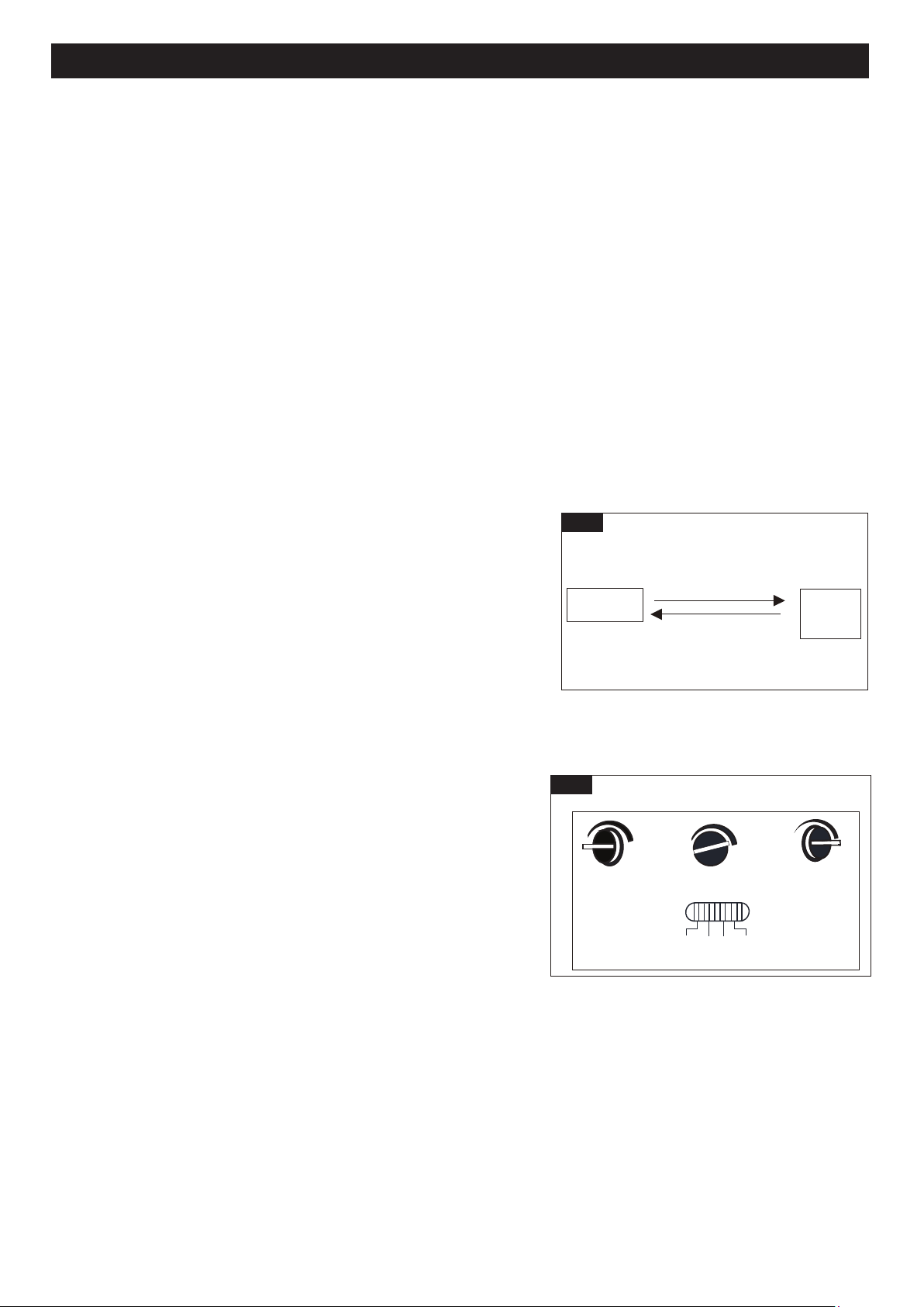
Fig. 5
Test
Off
Auto
PC
Low Level
(View from back of sensor head)
Time
Sens
Model
3. Auto MODE(nighttime operation only)
• At dusk, the light will turn to low-level brightness (0~50%). The light will turn to high-level brightness (full brightness)
when motion is detected, and stay on as long as the motion continues. When the motion stops, the light will remain
on for the predetermined time set (5 ~ 180 seconds), and then revert to low-level brightness you set.
• The light will turn off automatically at dawn.
4. PC MODE(nighttime operation only)
• The light will turn to high-level brightness (full brightness) at dusk. It will turn off at dawn.
5. Manual Override MODE (nighttime operation only)
• To shift to the manual override mode, set the switch to “Off” or “Auto”
mode. Turn the wall switch “OFF” and then turn it “ON” within 3
seconds. The light will remain on all night long. To shift back to the
“Off” or “Auto” mode, turn the wall switch “OFF” and then turn it “ON”
within 3 seconds again.(See Fig.4)
• The light will last only for one night and turn off automatically at dawn.
Note: 1.You can adjust the low level brightness (0~50%) by rotating
“Low Level” knob at the back of sensor lens.(See Fig.5)
2.To make sure the above functions operate properly, always
keep the wall switch in the “ON” position (including the daytime).
3. Please notice the warm up time is 100 seconds, any operations are invalid during this time.
Customization Options
Shut-off Delay
The Shut-off delay is the length of time the light will stay at high-level
brightness after motion has ceased to be detected. This Shut-off delay
can be set when operation is in “Off”, or “Auto” mode by using the
“Time” knob located on the left side of the panel at the back of sensor
head (See Fig.5) . To increase the shut-off delay, turn the knob
clockwise. To decrease shut off delay, turn the knob counterclockwise.
The delay may be adjusted from a minimum of 5 seconds to a maximum
of 3 minutes. The light will stay on as long as motion is detected
continuously and will automatically turn to low-level brightness when no
more motion is detected after the delay time has passed.
Sensitivity of Motion Sensor
The sensitivity of the motion sensor can be adjusted by using the “Sens” knob located on the right side of the panel at
the back of sensor lens (See Fig.5). To increase sensitivity, turn the knob clockwise. To decrease sensitivity, turn the
knob counterclockwise. The sensitivity may be adjusted from a minimum of 5 feet to a maximum of 40 feet.
Off Mode
Auto Mode
Manual
Override
Manual Override Operation Diagram
Turn wall switch OFF-ON
in 0.5~3 Seconds
Turn wall switch OFF-ON
in 0.5~3 Seconds
Fig. 4
FUNCTION AND OPERATION
Choose a mode by sliding the switch at the back of sensor lens. When power is first applied, the light will turn on
immediately. Wait for 100 seconds to allow the sensor to warm up.
1. TEST MODE (daytime and nighttime operation)
• The light will turn to low-level brightness (0~50%).The light will turn to high-level brightness (full brightness) when
motion is detected, and stay on as long as the motion continues. The light will revert to low-level brightness you set
about 5 seconds after motion is no longer detected.
2. Off MODE (nighttime operation only)
• At dusk, the light will turn to high-level brightness (full brightness) when motion is detected, and stay on as long as
the motion continues. When the motion stops, the light will remain on for the predetermined time set
(5 ~ 180 seconds), then the light will turn off automatically.
ASSEMBLY INSTRUCTIONS (continued)
ASSEMBLY INSTRUCTIONS (continued)
Page 5 of 6
NOTE:
1. The sensitivity of the motion sensor will increase as the
environmental temperature gets cooler. For best performance,
gently clean the lens with a soft cloth every 1 or 2 months to
assure maximum sensitivity.
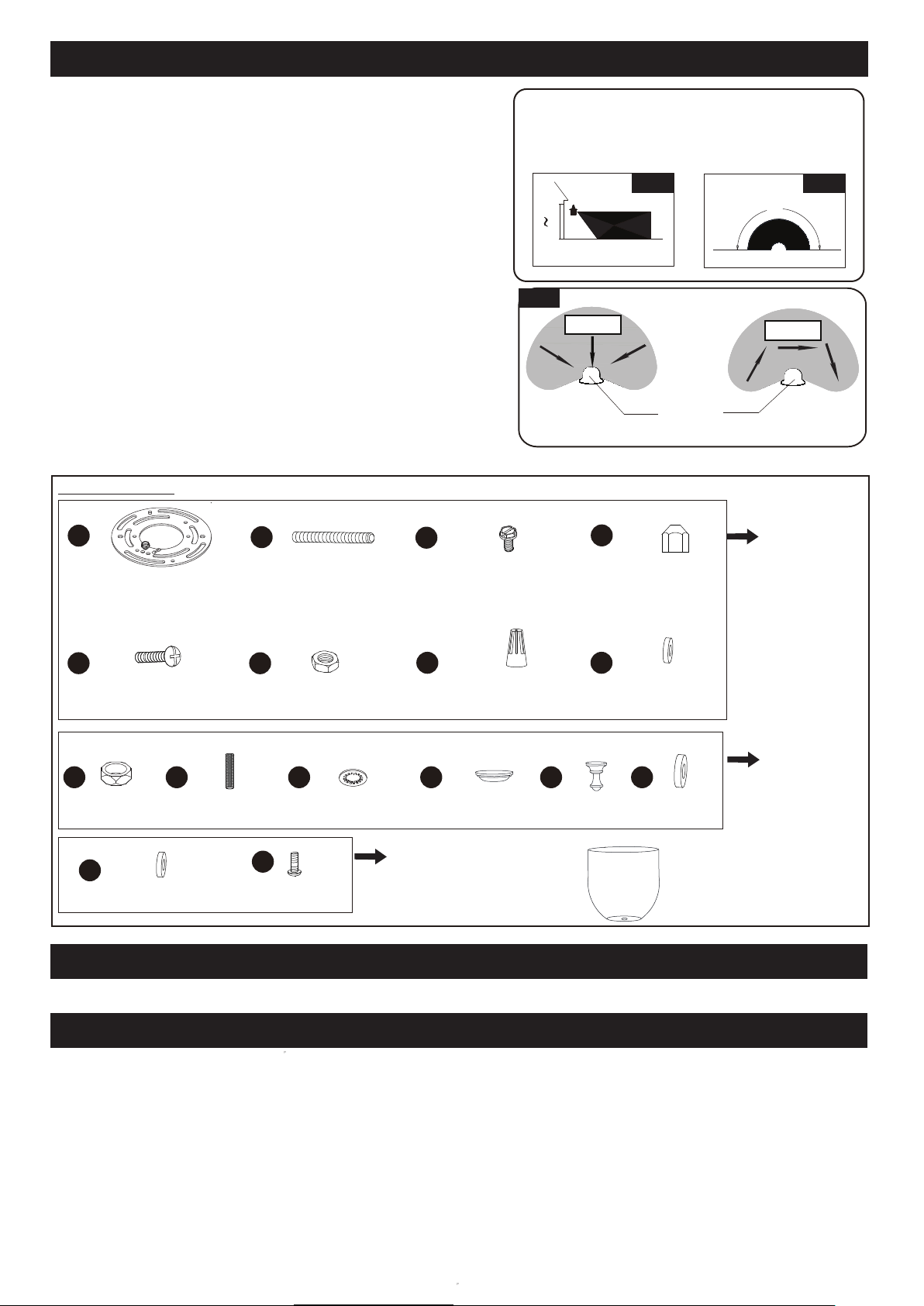
2. For best performance, install fixture at least 6 feet above
the ground. At such a height, the fixture will provide a
detection distance of up to 40 feet at 77 degrees
Fahrenheit. (See Fig.6)
3.The sensor detects across a detection range of 180 degrees.
(See Fig.7)
4. The sensor will be more sensitive to motion across its
detection path than motion directly towards it. (See Fig.8)
5. To reduce possible nuisances, do not mount the fixture
near a heat source like an air conditioner, vent or furnace
exhaust, or in a direction facing any reflecting object or
other light source.
CARE AND MAINTENANCE
● To clean, turn off and wipe with a damp, non-abrasive cloth.
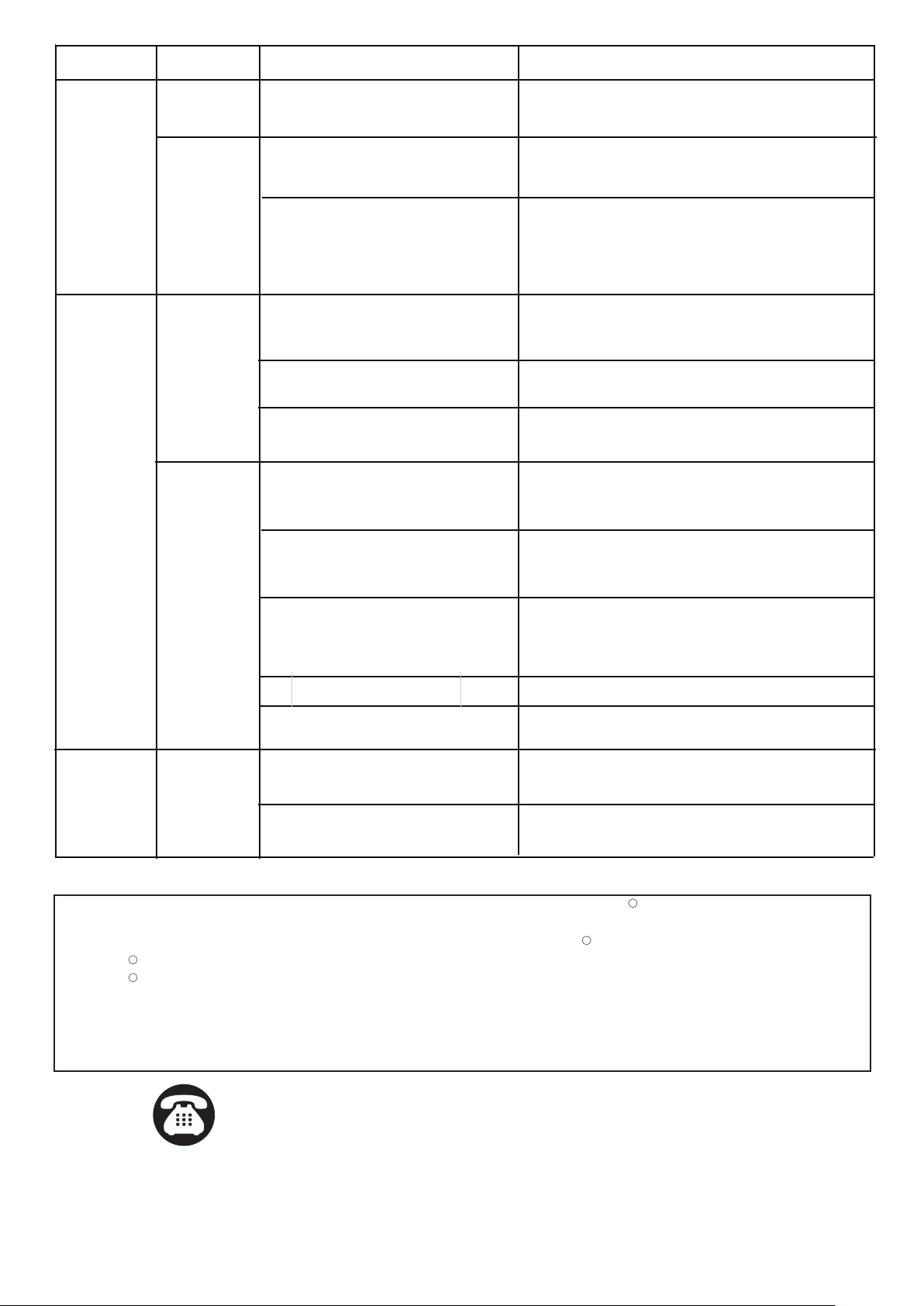
TROUBLESHOOTING
If the light does not work at all:First check the following aspects
1. Make sure the wall switch and circuit breaker are on.
2. Make sure the wiring is correct.
3. Make sure the bulb is not burned out,or loose
use bleow chart for troubleshooting your security light
FUNCTION AND OPERATION (continued)
The following parts are available for re-order if damaged or missing. Call us toll-free at 1-800-887-6326
Spare Parts List:
II JJ
Hex Nut
Washer
KK
Threaded Pipe
Glass
9998CS
LL
Decorated Cup
MM
NN
Finial
OO
Set Screw
X2
AA
BB
DD
EE
FF
GG
CC
Mounting Screw
X2
Green Grounding
Screw X1
Lock Nut
X4
Wire Connector
X3
HH
Rubber Pad
X2
Rubber Pad
Ball Nut
X2
Headless Screw
X2
HH
Rubber Pad
X2
Assembly Kit
5919MM (1 SET)
Assembly Kit
5920AA (1 SET)
Assembly Kit
5918MM (1 SET)
Mounting Plate
X1
5`
6`
10`
40`
Where you install your lantern is important:
Be sure the light is mounted straight on the wall;
otherwise, the detection distance may be limited.
Fig. 6 Fig. 7
180˚
Motion
Least sensitive
Motion
Most sensitive
Sensor
Fig. 8
Page 6 of 6
FIVE-YEAR LIMITED WARRANTY: If, during normal use, this PATRIOT LIGHTING lighting fixture breaks or fails
due to a defect in material workmanship within five (5) years from the date of original purchase, simply bring this
lighting fixture with the original sales receipt back to your nearest MENARDS retail store. At its discretion, PATRIOT
LIGHTING agrees to have the product or any defective part(s) repaired or replaced with the same or similar PATRIOT
LIGHTING product or part free of charge, within the stated warranty period, when returned by the original purchaser
with original sales receipt. This warranty; (1) excludes expendable parts including but not limited to light bulbs; (2) does
not cover damage that has resulted from abuse or misuse; and (3) does not cover any losses, labor, injuries to
persons/property or costs. This warranty does give you specific legal rights and you may have other rights, which vary
from state to state.
R
R
R
R
Questions, problems, missing parts?
Before returning to your retailer, call our customer service at 1-800-887-6326
Monday – Friday 9:00 a.m. – 5:00 p.m. CST
If unable to fix any of the above issues, please consult a certified electrician.
During the first installation, need to test product
function in the test mode.
Night
Confirm that light is on after cover the sensor by
hand, move another dark position.and avoid direct
sunlight.
Slide the switch to Auto mode.
The product may be installed in a
dark position, or it is shielded from
the sun.
After strong light on the sensor for over 5 seconds,
if it goes out,replace the install position or remove
the object
Ensure that the product is not detected.
Time delay accumulates under test
model.
A sudden or artificial power break
within 3 seconds, entering the
manual override mode.
Turn off the power, the initial setting will be restored
after more than 5 seconds.
False triggering caused by a heat
source, such as a heater or dryer vent,
or heated
swimming pool.
Eliminate heat source or relocate fixture.
In the Off / Auto mode, the sensor
has been measured to move the
object,and the high level delay time
is superimposed.
Ensure that no long-term moving objects around
the product.
In the PC mode.
Slide the switch to Off / Auto mode.
The switch is not slid into the position
of any model.
Slide it again to the model you want.
Light bulb quality or matching
problem.
It is normal to replace incandescent lamp instead of
confirming function nomally, otherwise change the
bulb.
If the light will
not come on
Day
Night
If the light
flashes or
blinks
Night
SYMPTOM
DAY/NIGHT
POSSIBLE CAUSE
SOLUTION
Day
Test product functionality not in test
mode.
It is possible to install where there
is bright light.
In the off mode,When the motion
stops, the light will remain on for
the predetermined time set
(5 ~ 180 seconds), then the light
will turn off automatically.
On cloudy or overcast days,the light
may stay on longer than anticipation.
No corrective action needed.
If the light
stays on
There are passing cars and reflective
objects that interfere with the sensor.
Replace the installed position.