Model No.: # 355-0741
PAGE: 1 / 11
220411
11
15
2
12
13
14
7
6
5
8
9
10
4
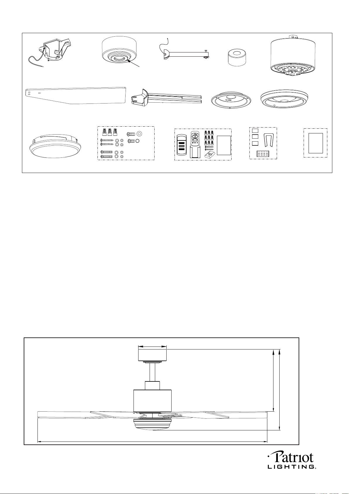
Unpack your fan and check the contents.You should have the following items.
1.) Hanger Bracket
2.) Canopy
3.) Decorative Cap (Remove the Preassembled Decorative Cap from the Canopy Before Installation.)
4.) Downrod Set (Included Hanger Ball, 6” Downrod, Hanger Pin & Lock Pin)
5.) Downrod Stand Cover
6.) Fan Motor Assembly
7.) Fan Blades (6 PCS)
8.) Blade Brackets (6 PCS)
9.) Connect Plate of Light Kit
10.) Light Kit with LED Module
11.) Glass Shade
12.) Assembly Kit
13.) Remote Control Set (Includes Receiver & Transmitter & Wire Connectors & Battery
& Screws & Remote Control Instructions)
14.) Blade Balancing Kit
15.) Installation Instructions
Package Contents:
1
Installation
Instructions
X 19
Dimension Reference (Installed with 6” Downrod):
A. 15-3/4” B. 12-1/4” C. 44” D. 5-1/2”
3
Remote
Control
Instructions
D
C
B
A
PAGE: 2 / 11
220411
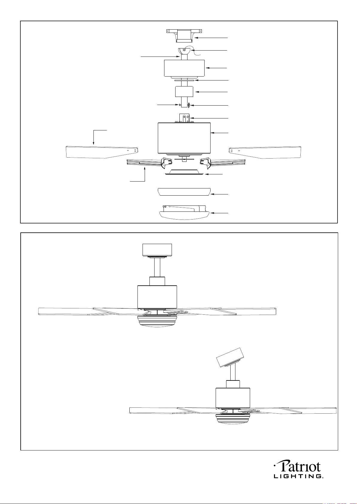
Exploded View Detail
Hanger Bracket
Hanger Ball
Fan Blade
Downrod
Lock Pin
Canopy
Decorative Cap
Hang Pin
Downrod Stand Cover
Collar
Blade Bracket
Connect Plate of Light Kit
Dual Mount Drawing
Downrod Mount
Sloped Ceiling Mount ( Up to 23 degrees)
Fan Motor Assembly
Light Kit with LED Module
Glass Shade
PAGE: 3 / 11
220411
PAGE: 4 / 11
Safety Instructions
READ ALL SAFETY INFORMATION AND INSTALLATION INSTRUCTIONS BEFORE YOU BEGIN TO
INSTALL THE FAN AND SAVE INSTRUCTIONS.
All set screws of the fan must be checked and retightened where necessary before installation.
To reduce the risk of personal injury, do not bend the blade brackets when installing the brackets,
balancing the blades or cleaning the fan. Do not insert foreign objects between rotating fan blades.
The fan blades must be turned on and spinning. Then press reverse button on remote control to
change the fan direction.
The safeguards provided by these safety instructions and by the separate installation instructions are
not meant to cover all possible conditions and situations that may occur. It must be understood that
common sense, caution and care are factors which can not be built into this product. These factors
must be supplied by the person(s) installing, caring for and operating the fan.
TO AVOID RISK OF ELECTRIC SHOCK, BE SURE TO SHUT OFF POWER AT THE MAIN
FUSE OR CIRCUIT BREAKER BOX BEFORE INSTALLING OR SERVICING THIS
FIXTURE. TURNING OFF THE ELECTRICAL POWER BY USING THE LIGHT SWITCH
IS NOT SUFFICIENT TO PREVENT ELECTRICAL SHOCK.
TO REDUCE THE RISK OF INJURY, INSTALL THE FAN SO THAT THE BLADES ARE
AT LEAST 7 FEET (2.1 METERS) ABOVE THE FLOOR AND AT LEAST 18 INCHES
(0.5 METERS) FROM THE TIP OF THE BLADES TO THE WALL.
TO REDUCE THE RISK OF FIRE, ELECTRIC SHOCK, OR PERSONAL INJURY, MOUNT
TO OUTLET BOX MARKED "ACCEPTABLE FOR FAN SUPPORT" AND USE MOUNTING
SCREWS PROVIDED WITH THE OUTLET BOX.
THE INSTALLATION HAS TO BE IN ACCORDANCE WITH THE NATIONAL ELECTRICAL
CODE, ANSI/NFPA 70-1999 AND LOCAL CODES. IF YOU ARE UNFAMILIAR WITH THE
METHODS OF INSTALLING ELECTRICAL WIRING, SEEK THE SERVICES OF A
QUALIFIED LICENSED ELECTRICIAN.
WARNING
220411
Note: For sloped ceiling installation, make
sure that the chip of the hanger bracket
is toward the floor.
IMPORTANT:
BEFORE YOU BEGIN INSTALLATION, CAREFULLY READ ALL INFORMATION PROVIDED IN THE SAFETY
INSTRUCTIONS AND INSTALLATION INSTRUCTIONS. IF IN DOUBT, CONSULT A QUALIFIED
ELECTRICIAN.
SAVE ALL INSTRUCTIONS.
Tighten the two collar screws.
Slide lock pin into hanger pin until
it is locked into position.
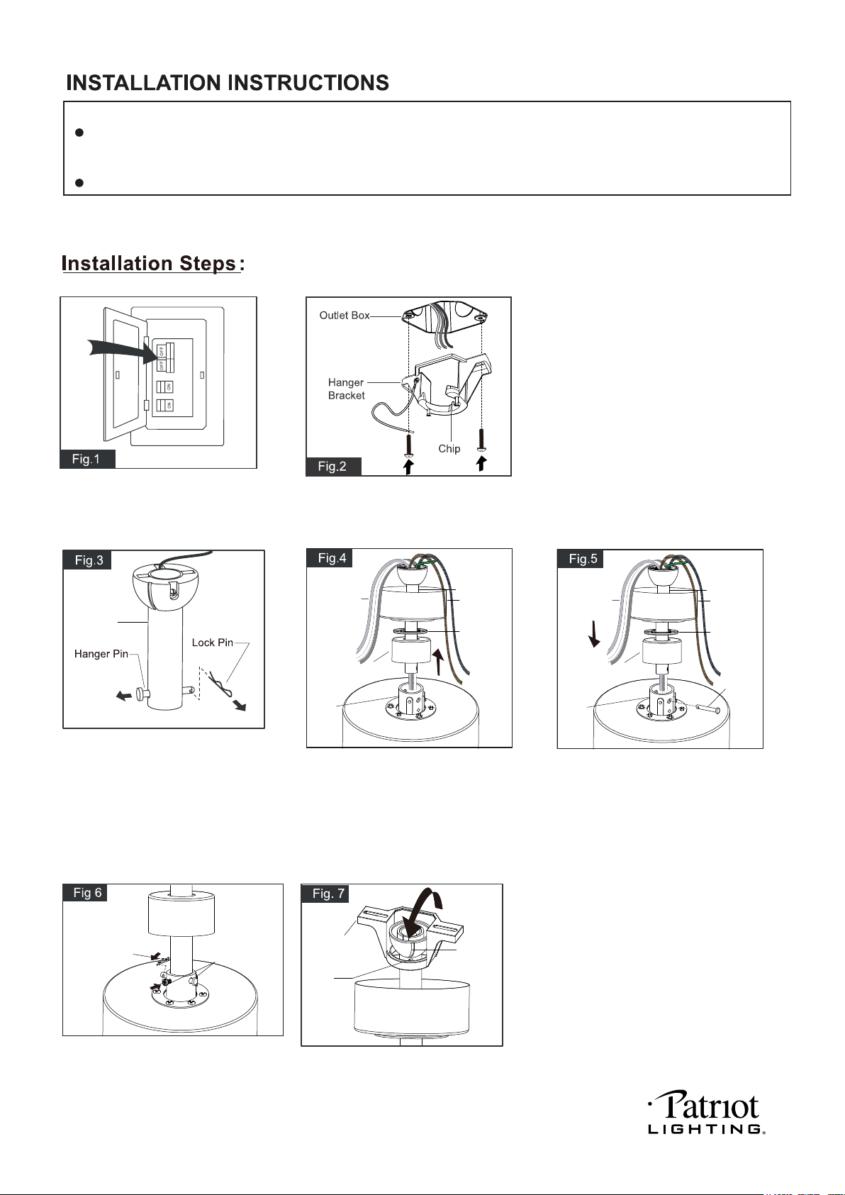
Remove the lock pin from the
hanger pin and remove the
hanger pin from the downrod.
Turn OFF the electric circuit at the
main fuse fuse or circuit breaker box.
Thread the motor wires through the
downrod stand cover, decorative cap
(Making sure the smooth side of
decorative cap is facing downward.),
canopy and downrod.
Loosen the collar screws out part way.
Insert the downrod into the collar.
Slide hanger pin through holes of
collar and downrod.
Hang the fan on hanger bracket, and
make sure the slot of hanger ball is
snapped into the chip of hanger bracket
exactly.
Note: For sloped ceiling installation,
make sure the slot of hanger ball and
the chip of hanger bracket face down.
Separate the hanger bracket from the decorative
cap and canopy by rotating counterclockwise.
Attach the hanger bracket to the outlet box with
two mounting screws. (To reduce the risk of fire,
electric shock, or personal injury, mount to an
outlet box marked "Acceptable for fan support"
and use mounting screws provided with the
outlet box.)
NOTE: The fan weight is 13.67 lbs (6.2 kg). Be sure the outlet box you are using is securely attached to the building
structure and can support the full weight of the fan. Failing to do so can result in serious injury.
Collar
Motor Wires
Decorative
Cap
Downrod Stand
Cover
Canopy
Downrod
Hanger
Pin
Collar
Motor Wires
Decorative
Cap
Downrod Stand
Cover
Canopy
Downrod
Lock Pin
Collar Screws
Hanger Bracket
Chip
Slot
PAGE: 5 / 11
Downrod
220411
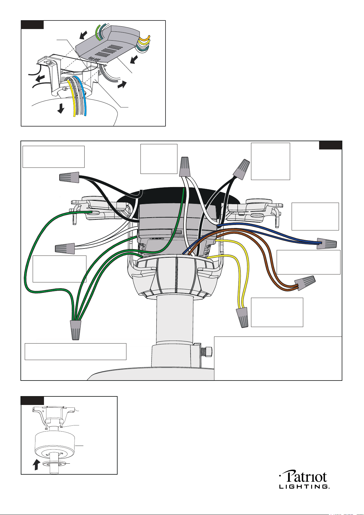
Move ground wires (a), outlet box wires (b), and motor
wires (c) away from the center of the hanger bracket as
shown. Thread the antenna through the hanger bracket
first, then thread the receiver through the hanger bracket
until it is placed in the center. Finally, cut motor wires (c) to
length needed for connections.
Black
Black
Black
Black
Connect the white
wire from receiver
to the white wire
from motor with a
wire connector
Connect the black
wire from receiver
to the black wire
from motor (This is
for fan control) with
a wire connector.
White
White
White
White
Connect the blue wire
from receiver to the
blue wire from motor
(This is for light control)
with a wire connector.
Connect the orange wire from
receiver to the orange wire from
motor (This is for reversible
function) with a wire connector.
Connect the yellow wire
from receiver to the yellow
wire from motor (This is
for reversible function)
with a wire connector.
Connect four ground wires (Green or bare copper)
coming from outlet box, downrod, hanging bracket
and receiver of remote control with a wire connector.
Connect the white (neutral)
wire from receiver to the
white (neutral) wire from
the outlet box with a
wire connector.
Connect the black (hot) wire
from receiver to the black (hot)
wire from outlet box with a wire
connector.
*** After making the wire connections, the wires should be spread
apart. The white (neutral) conductor from receiver and outlet
box with green (grounding) conductor on one side; the black
(hot) conductor from receiver and outlet box with the white,
black, blue, orange and yellow conductor from receiver and
motor on the other side of the outlet box.
*** The wire connection points should be turned upward and
pushed carefully up into outlet box.
Fig.9
Slide the canopy up to ceiling and over the two canopy screws on hanger
bracket. Rotate canopy clockwise, next, while holding the canopy with one
hand, slide the decorative cap over the screws and rotate clockwise until tight.
Note: Adjust the canopy screws as necessary until the canopy and
canopy cover are snug.
Green
Green
Blue
Blue
Orange
Yellow
Yellow
Fig.8
Antenna
Receiver
Hanger Bracket
a.
c.
b.
PAGE: 6 / 11
Fig.10
Canopy Screw
Hanger Bracket
Canopy
Decorative Cap
220411
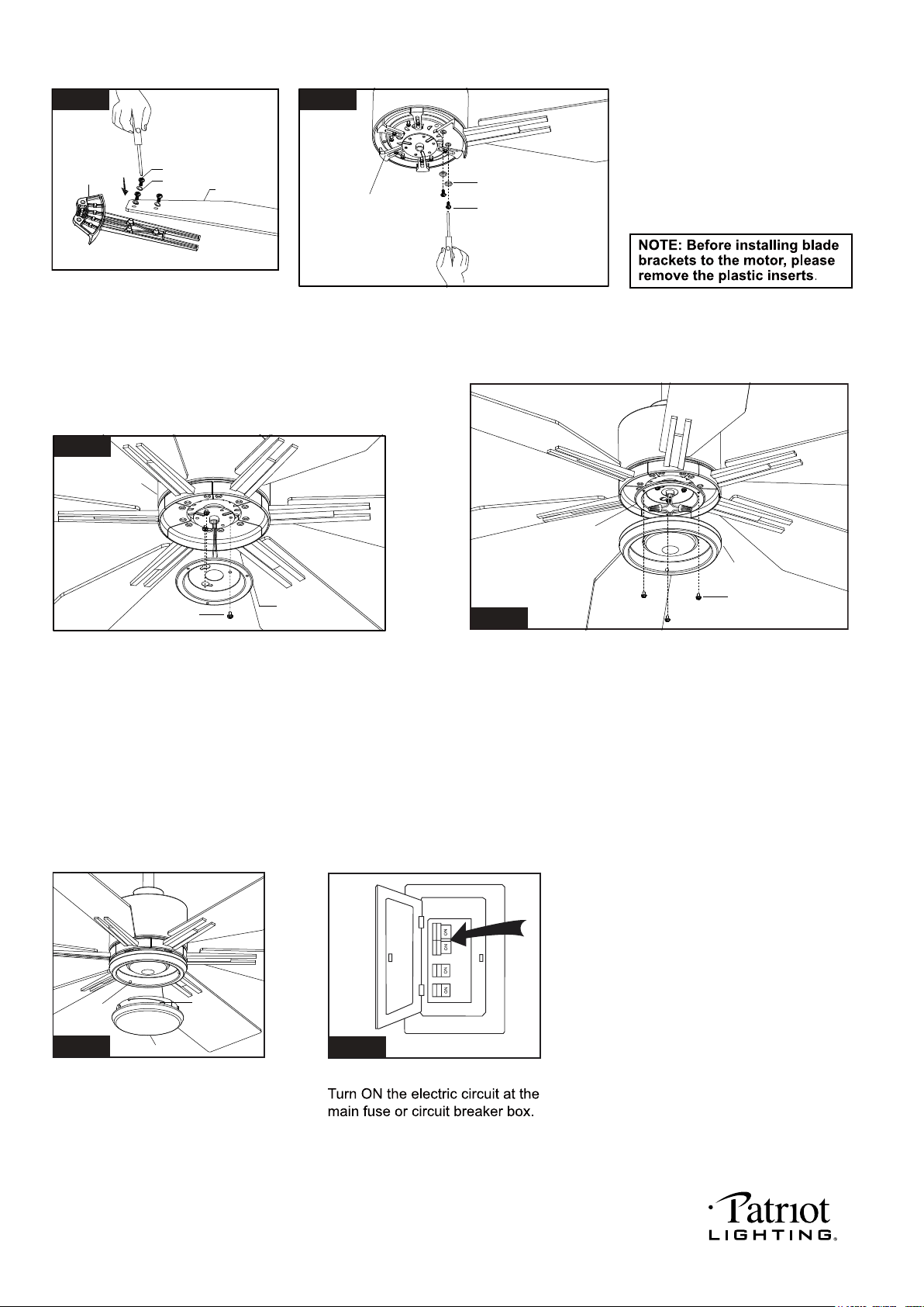
Tighten blades to blade brackets
by using blade screws and washers.
Remove the motor screws, plastic
inserts and washers from the fan
motor assembly. Secure blade
brackets to the motor with washers
and motor screws.
Blade Bracket
Blade
Washer
Blade Screw
Fig.11
PAGE: 7 / 11
Attach the glass shade to the
light kit by aligning studs and
slots, and turn clockwise until
it is locked in place.
Stud
Slot
Glass Shade
Fig.15
Remove three screws from connect plate of light kit first. Then
connect the white (neutral) wire from the light kit to white
(neutral) wire from fan motor assembly with a wire connector;
connect the black (hot) wire from light kit to blue (hot) wire from
fan motor assembly with a wire connector. Carefully put the
wires into the connect plate of light kit, then attach the light kit
onto the connect plate of light kit with the connect plate screws.
Remove one screw and loosen another two screws
from fan motor assembly first, then thread the fan motor
assembly wires through connect plate of light kit, then
push the connect plate of light kit upwards until the
fan motor assembly screws insert into the key hole
slots of connect plate of light kit, then rotate the connect
plate of light kit until it’s fixed on the fan motor assembly
bottom. Finally, secure the connect plate of light kit to
the fan motor assembly bottom with previous screw which
was removed. Tighten the other two fan motor assembly screws.
Fan Motor Assembly
Fix Screw
Connect Plate
of Light Kit
Fig.13
Connect Plate Screw
Connect Plate
of Light Kit
Light Kit
Fig.14
Fig.16
Fig.12
Washer
Motor Screws
Plastic Insert
220411
Note: 1. Remote controller can not be used along with a solid-state speed control at the same time.
2. The direction of fan rotation can’t be set without remote controller.
3. The temperature and brightness
of light can not be set without remote controller.
Fig.19
Fig.20
Receiver
Canopy
Hanger Bracket
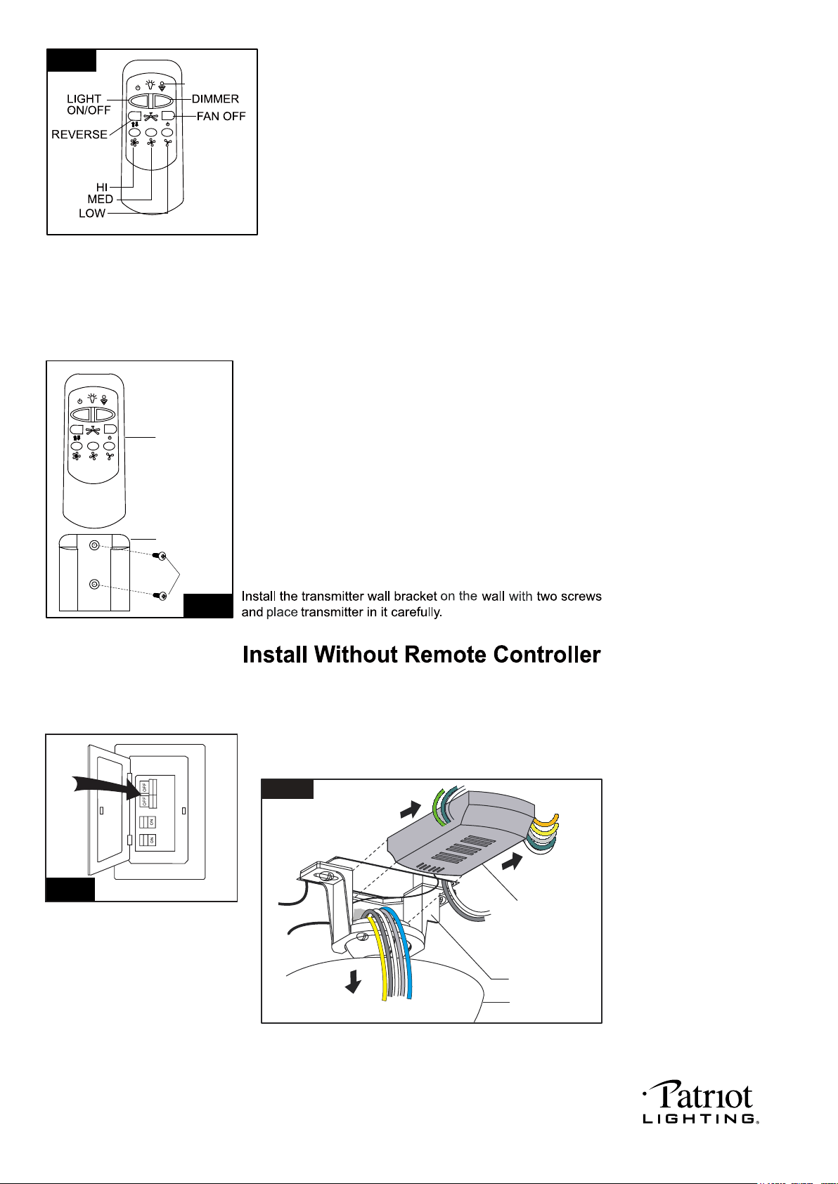
Turn OFF the electric circuit at the main fuse or circuit breaker box. (See Fig.19)
Unscrew the canopy. Remove the wire connectors from the fan to ceiling
wire connection. The receiver should be removed from the hanger bracket.
(See Fig.20)
Transmitter
Wall Bracket
Screw
Fig.18
Fig.17
Install the battery (9V, included) into the transmitter.
LED
INDICATOR
* Press "HI" button to turn on the fan at high speed.
* Press "MED" button to turn the fan in medium speed.
* Press "LOW" button to turn the fan in low speed.
* Press "FAN OFF" button to turn off the fan.
* Press "REVERSE" button to set direction of fan rotation.
The fan speed will slow down until the fan is turned off and it will restart by spinning in the
reverse direction and resume the previously selected speed setting.
* Press "LIGHT ON /OFF" button to turn on or turn off the light.
* Press and hold the "DIMMER" button to dim or brighten lights to the desired level and
release, and the brightness level will be memorized.Turn on the light again, then fan
light will be restored to the brightness-level at which it was dimmed last time.
* Press "DIMMER" button to change color temperature of fan light. There are a total of
5 levels of color changing from 2700K,3000K,3500K,4000K to 5000K.
Note:
1. This remote controller has a memory function setting. The fan will operate at the same
speed and the fan light will stay at the same brightness-level as the last time the power
supply was turned off.
2. Compatible Wall Switch: Menards SKU# 363-5580.
a. Warning: This wall switch is not capable of changing the temperature and brightness
of the light. Therefore, it’s important to set your preferred color temperature and
brightness before removing the remote-control receiver from the fan.
b. This LED module has a memory function setting. The fan light will stay at the same
brightness and temperature as the last time of remote control setting.
c. The direction of fan rotation can’t be set without remote controller.
d. The fan speed will be stay at high speed after remove the remote controller.
Please use wall control to adjust the speed which you need. To proceed with installation
without remote control, please start from Fig.19.
Operating transmitter:
Set the code:
Within the 10 second time frame after the main power is turned on, press and hold FAN OFF
button for more than 3 seconds. The LED light will begin to flash. Once the code is set
successfully, the fan will turn off and the light will turn on.
Note: The included transmitter was paired with the receiver at the factory with default
settings, so no need to set the code again. Go through these setup steps if you found
your transmitter can’t communicate with the receiver.
PAGE: 8 / 11
220411
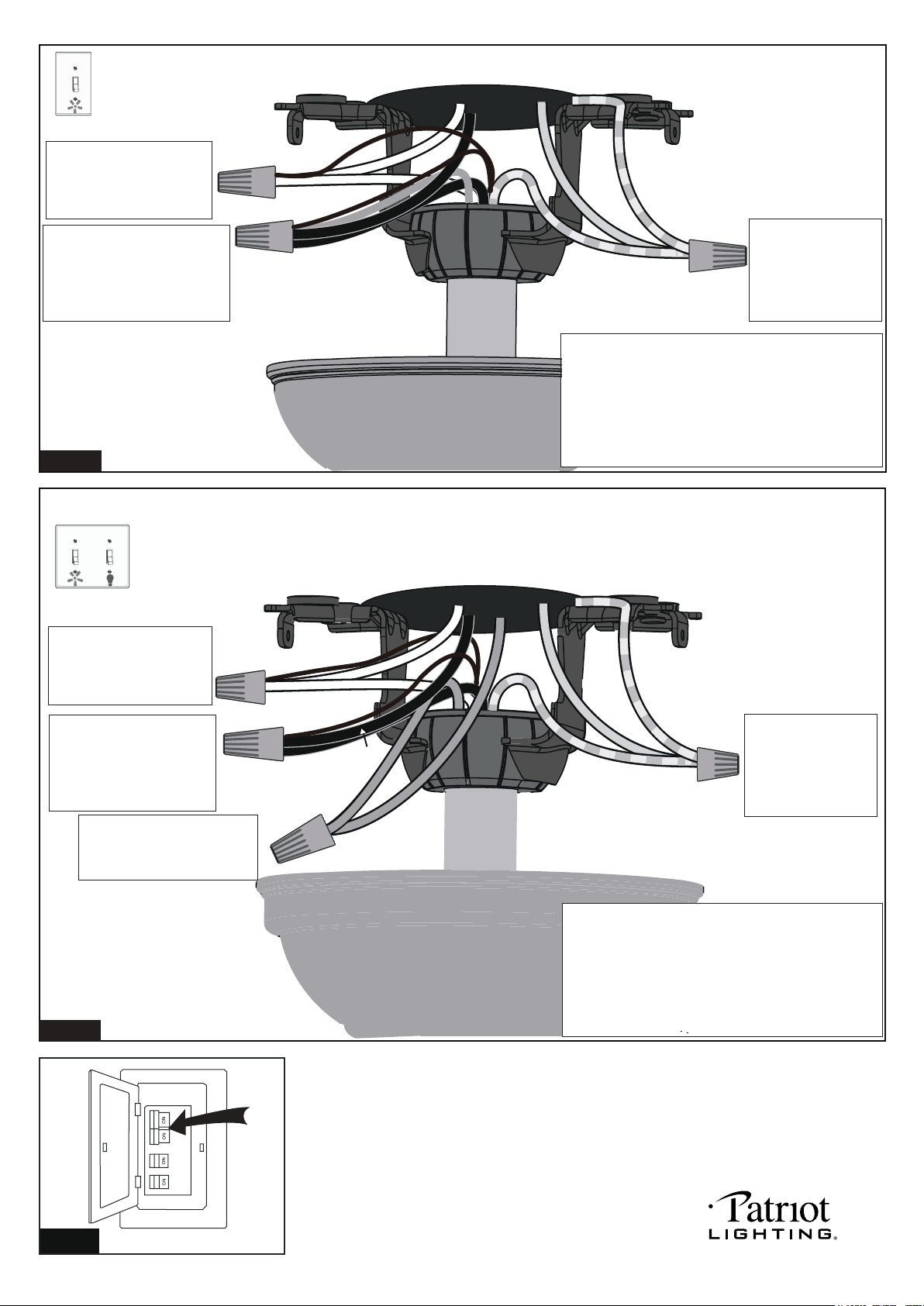
Fig.21
Connect the white (neutral)
wire and orange reversible
wire from motor to the white
(neutral) wire from the outlet
box with a wire connector.
Connect the black (hot) wire
(This is for fan control), blue wire
(This is for light control) and
yellow reversible wire from motor
to the black (hot) wire from outlet
box with a wire connector.
Bla
Black
ck
Blue
Green
White
White
Orange
Yellow
Grounding
Green
Connect three
ground wires (Green
or bare copper) coming
from outlet box,
downrod and hanging
bracket with a wire
connector.
For a single switch
Follow these steps:
Connect three
ground wires (Green
or bare copper) coming
from outlet box,
downrod and hanging
bracket with a wire
connector.
Green
Black
Black
Blue
Green
White
Orange
Yellow
Blue
(light)
White
Grounding
Connect the black (hot) wire
(This is for fan control) and
yellow reversible wire from
motor to the black (hot) wire
from outlet box with a wire
connector.
Connect the white (neutral)
wire and orange reversible
wire from motor to the white
(neutral) wire from the outlet
box with a wire connector.
Connect the blue wire (This
is for light control) from motor
to the blue wire from outlet box
with a w ire connector.
*** The wire connection points should be turned
upward and pushed carefully up into outlet box.
Fig.23
Turn ON the electric circuit at the main fuse or circuit breaker box.
For dual switches
Follow these steps:
*** After making the wire connections, the wires should
be spread apart. The white (neutral) conductor from
motor and outlet box, orange conductor from motor
with green (grounding) conductor on one side; the
black (hot) and blue conductor from motor and outlet
box with the black, blue, yellow conductor from motor
on the other side of the outlet box.
Fig.22
PAGE: 9 / 11
*** After making the wire connections, the wires should
be spread apart. The white (neutral) conductor from
motor and outlet box, orange conductor from motor
with green (grounding) conductor on one side; the
black (hot) conductor from motor and outlet box
with the black, blue, yellow conductor from motor
on the other side of the outlet box.
*** The wire connection points should be turned upward
and pushed carefully up into outlet box.
220411
too tight
PAGE: 10 / 11
220411
PAGE: 11 / 11
220411
