
Model No.: # 355-0781
PAGE: 1 / 12
221212
13
17
2
14
15
16
8
6
7
5
9
10
11 12
3
4
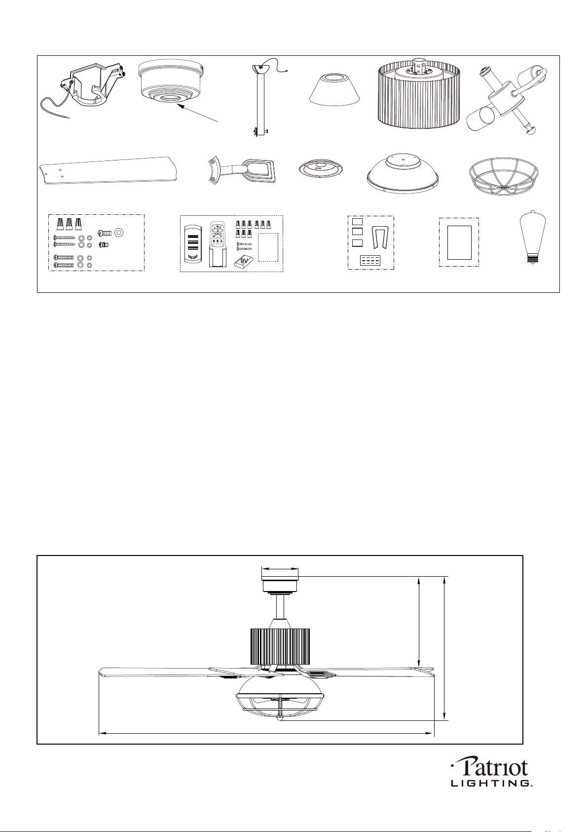
Unpack your fan and check the contents. You should have the following items.
1.) Hanger Bracket
2.) Canopy
3.) Canopy Cover (Remove the Preassembled Canopy Cover from the Canopy Before Installation.)
4.) Downrod Set (Included Hanger Ball, 6” Downrod, Hanger Pin & Lock Pin)
5.) Downrod Stand Cover
6.) Fan Motor Assembly
7.) Light Kit
8.) Fan Blades (5 PCS)
9.) Blade Brackets (5 PCS)
10.) Connect Plate of Light Kit
11.) Metal Cover of Light Kit
12.) Metal Cage
13.) Assembly Kit
14.) Remote Control Set (Includes Receiver & Transmitter & Wire Connectors & Battery
& Screws & Remote Control Instructions)
15.) Blade Balancing Kit
16.) Installation Instructions
17.) 6W E26 (M) Base ST19 Type LED Bulb (2pcs)
Package Contents:
1
Installation
Instructions
X 16
Dimension Reference (Installed with 6" Downrod):
A. 21" B. 15" C.52" D. 5-1/8"
PAGE: 2 / 12
Remote
Control
Instructions
2H 4H 8H
C
A
B
D
221212
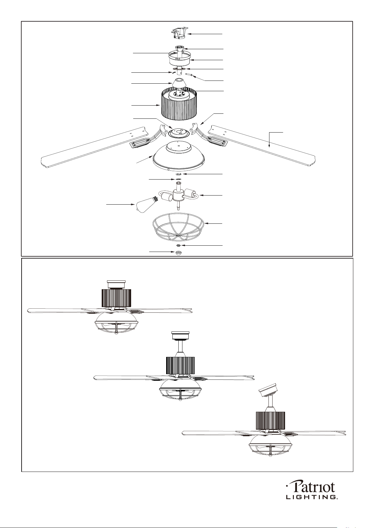
Exploded View Detail
Hanger Bracket
Hanger Ball
Canopy
Canopy Cover
Downrod Stand Cover
Collar
Blade Bracket
Connect Plate of Light Kit
Light Kit
Metal Cover of Light Kit
Washer
LED Bulb
Fan Blade
Lock Pin
Downrod
Fan Motor Assembly
Triple Mount Options
Ceiling Mount
Downrod Mount
Sloped Ceiling Mount ( Up to 23 degrees)
PAGE: 3 / 12
Hex Nut
Hex Nut
Metal Cage
Finial
Hang Pin
221212
PAGE: 4 / 12
The fan blades must be turned on and spinning. Then press reverse button on remote control to
change the fan direction.
221212
NOTE: The fan weight is 17.55 lbs (7.95 kg). Be sure the outlet box you are using is securely attached to the building
structure and can support the full weight of the fan. Failing to do so can result in serious injury.
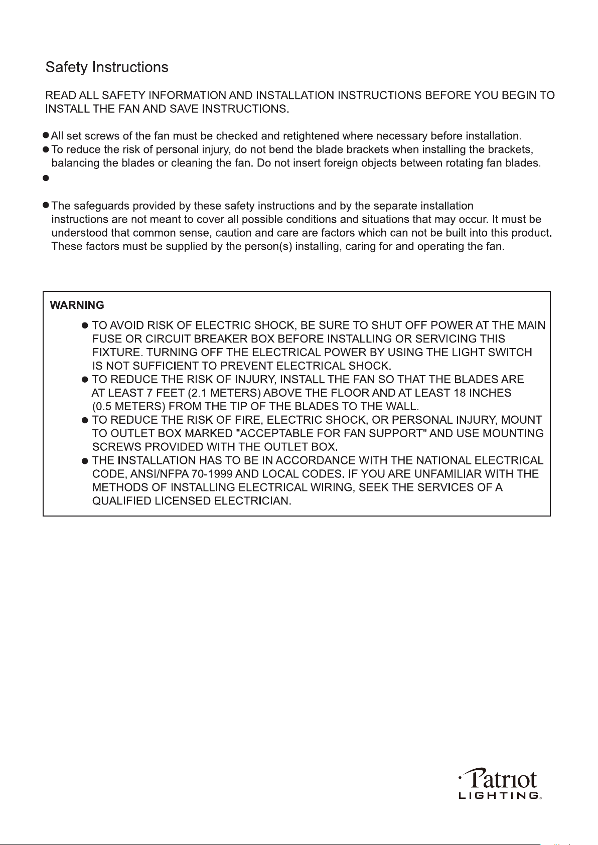
INSTALLATION INSTRUCTIONS
IMPORTANT:
BEFORE YOU BEGIN INSTALLING THE FAN, CAREFULLY READ ALL INFORMATION IN
SAVE ALL INSTRUCTIONS.
Installation Steps :
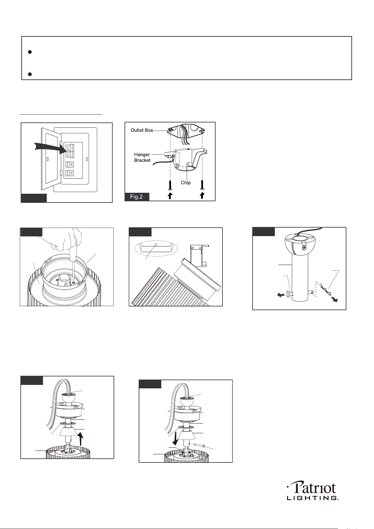
Fig.1
Turn OFF the electric circuit at the
main fuse or circuit breaker box.
THE SAFETY
INSTRUCTIONS AND INSTALLATION INSTRUCTIONS. IF IN DOUBT, CONSULT A QUALIFIED
ELECTRICIAN.
(For downrod mount only):
Remove the lock pin from hanger
pin and remove the hanger pin
from the downrod.
(For ceiling mount only):
Remove the canopy cover from the
canopy. Remove downrod stand cover
and three of six screws (every other one)
securing the motor collar to the top
of the fan motor housing. Attach the
canopy to the housing with three screws.
(For ceiling mount only):
Raise the fan and place the canopy
on the hanger bracket hook for wiring.
Go to Fig.10 for the next steps.
(For downrod mount only):
Thread the motor wires through the
downrod stand cover, canopy cover
(Making sure the smooth side of
canpoy cover is facing downward.),
canopy and downrod.
(For downrod mount only):
Loosen the collar screws out part way.
Insert the downrod into the collar.
Slide hanger pin through holes of
collar and downrod.
PAGE: 5 / 12
Hanger Pin
Downrod
Lock Pin
Fig.5
Downrod
Downrod
Stand Cover
Canopy Cover
Collar
Fig.6
Motor Wires
Canopy
Downrod
Downrod
Stand Cover
Hanger Pin
Collar
Fig.7
Motor Wires
Canopy
Canopy Cover
Collar Screw
Attach the hanger bracket to the outlet box with
two mounting screws. (To reduce the risk of fire,
electric shock, or personal injury, mount to an
outlet box marked "Acceptable for fan support"
and use mounting screws provided with the
outlet box.)
Note: For sloped ceiling installation, make
sure that the chip of the hanger bracket
is toward the floor.
Fig.3
Fig.4
Housing
Canopy
Hanger Bracket
Hook
221212
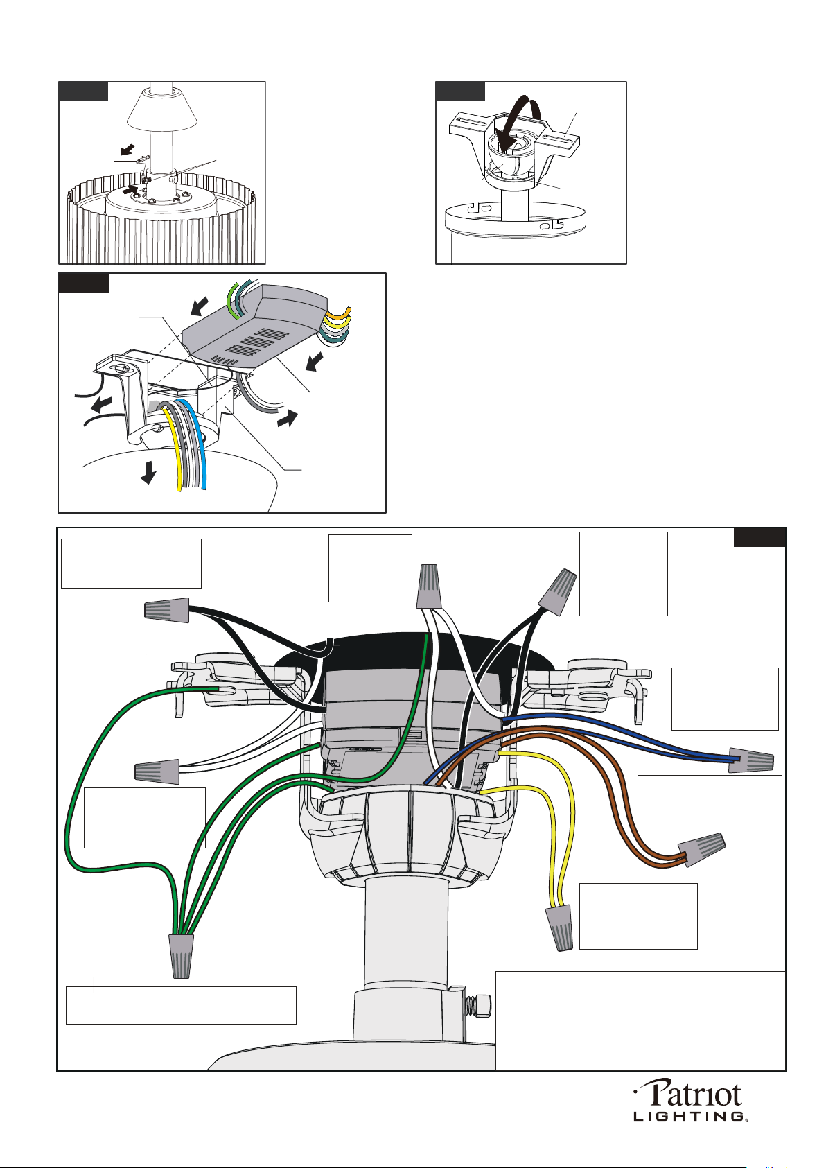
(For downrod mount only):
Tighten the two collar screws.
Slide lock pin into hanger pin
until it is locked into position.
(For downrod mount only):
Hang the fan on hanger
bracket, and make sure the
slot of hanger ball is snapped
into the chip of hanger bracket
exactly.
Note: For sloped ceiling
installation, make sure
the slot of hanger ball
and the chip of hanger
bracket face down.
Fig.8
Collar Screw
Lock Pin
Fig.9
Hanger Bracket
Slot
Chip
Hanger
Ball
Move ground wires (a), outlet box wires (b), and motor
wires (c) away from the center of the hanger bracket as
shown. Thread the antenna through the hanger bracket
first, then thread the receiver through the hanger bracket
until it is placed in the center. Finally, cut motor wires (c) to
length needed for connections.
Fig.10
Antenna
Receiver
Hanger Bracket
a.
c.
b.
PAGE: 6 / 12
Black
Black
Black
Black
Connect the white
wire from receiver
to the white wire
from motor with a
wire connector
Connect the black
wire from receiver
to the black wire
from motor (This is
for fan control) with
a wire connector.
White
White
White
White
Connect the blue wire
from receiver to the
blue wire from motor
(This is for light control)
with a wire connector.
Connect the orange wire from
receiver to the orange wire from
motor (This is for reversible
function) with a wire connector.
Connect the yellow wire
from receiver to the yellow
wire from motor (This is
for reversible function)
with a wire connector.
Connect four ground wires (Green or bare copper)
coming from outlet box, downrod, hanging bracket
and receiver of remote control with a wire connector.
Connect the white (neutral)
wire from receiver to the
white (neutral) wire from
the outlet box with a
wire connector.
Connect the black (hot) wire
from receiver to the black (hot)
wire from outlet box with a wire
connector.
*** After making the wire connections, the wires should be spread
apart. The white (neutral) conductor from receiver and outlet
box with green (grounding) conductor on one side; the black
(hot) conductor from receiver and outlet box with the white,
black, blue, orange and yellow conductor from receiver and
motor on the other side of the outlet box.
*** The wire connection points should be turned upward and
pushed carefully up into outlet box.
Fig.11
Green
Green
Blue
Blue
Orange
Yellow
Yellow
221212
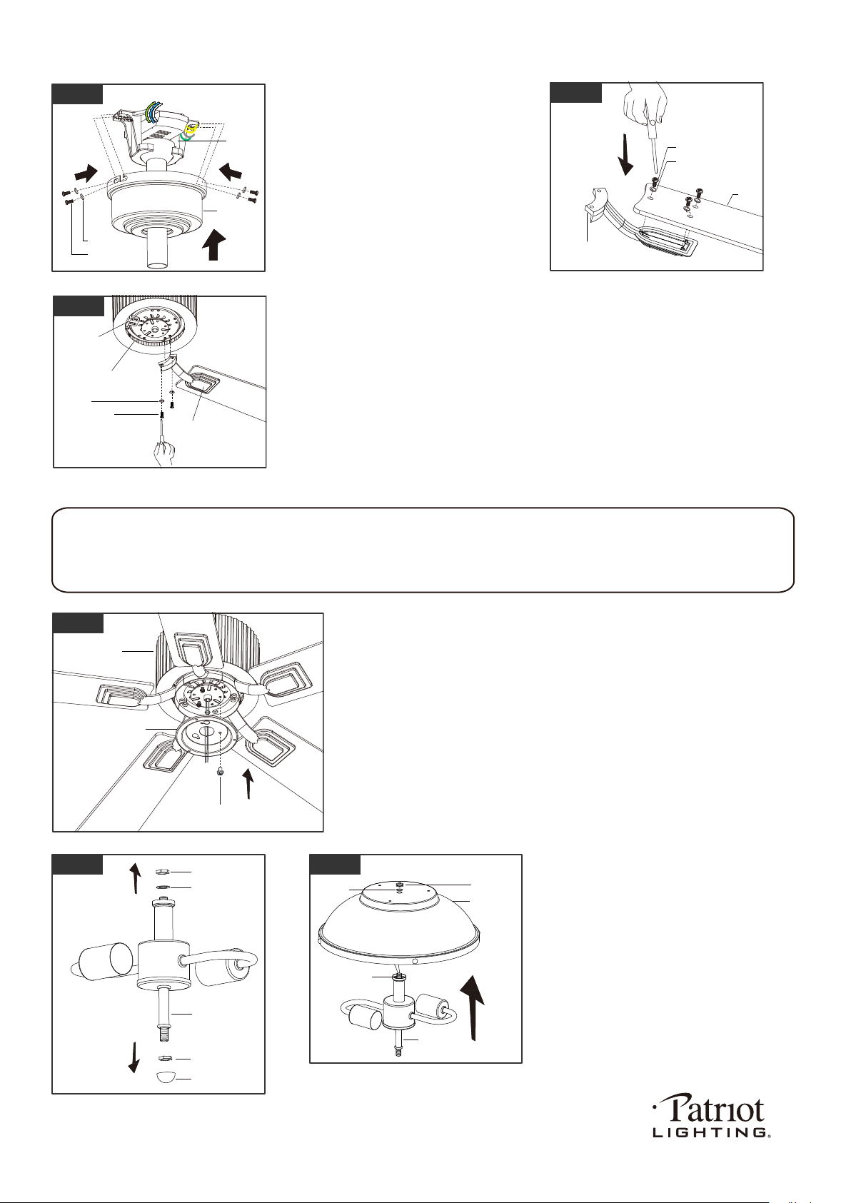
Tighten blades to blade brackets by
using blade screws and washers.
Remove the motor screws, plastic insert and washers from the fan assembly.
Secure blade brackets to the motor with washers and motor screws.
Note:
1. Making sure the side of blade bracket is facing downward.
2. Before installing blade brackets the motor, please remove the plastic insert.
Remove one screw and loosen another two screws from fan motor
assembly first, thread the fan motor assembly wires through connect
plate of light kit, then push the connect plate of light kit upwards until
the fan motor assembly screws insert into the key hole slots of connect
plate of light kit, then rotate the connect plate of light kit until it’s fixed
on the fan motor assembly bottom. Finally, secure the connect plate
of light kit to the fan motor assembly bottom with previous screw
which was removed. Tighten the other two fan motor assembly screws.
There are four hanger bracket screws
and lock washers. Remove two screws
and lock washers from the hanger
bracket (one from each side) and loosen
the other two remaining screws. Align
the "L shaped" slots of the canopy with
the two remaining screws on the hanger
bracket and push the canopy upwards to
engage the slots and turn clockwise to
lock in place. Tighten the screws and
install the other two hanger bracket
screws and lock washers into the
remaining holes of the canopy and tighten.
PAGE: 7 / 12
Fig.12
Canopy
Lock Washer
Screw
Hang
Bracket
Blade Screw
Blade Bracket
Blade
Washer
Fig.13
Remove two hex nuts, lock washer and
finial from light kit before installation and
keep these for later use.
Attach the light kit to the metal cover of light kit
by threading the light kit wires (black and white)
and remove threaded pipe through the hole of
metal cover of light kit and then secure them
onto the metal cover of light kit with washer
and hex nut. Be sure it is tight enough to
prevent light kit from vibrating loose.
Motor Screw
Washer
Blade Bracket
Fan Motor Assembly
Plastic Insert
Fig.14
Fig.16
Light Kit
Hex Nut
Washer
Finial
Hex Nut
Fig.17
Metal Cover
of Light Kit
Light Kit
Hex Nut
Threaded Pipe
Washer
Connect Plate of
Light Kit
Fan Motor Assembly Screw
Fan Motor
Assembly
Fig.15
Install fan light
WARNING:
This fan light has a built-in current limiting device in the receiver of remote control to conserve energy. The fan light
will shuts off shortly if the combined wattage of the installed bulbs exceeds 190Watts. Please replace light bulbs
with lower wattage bulbs which show on relamping label or package and then turn on the fan light again.
221212
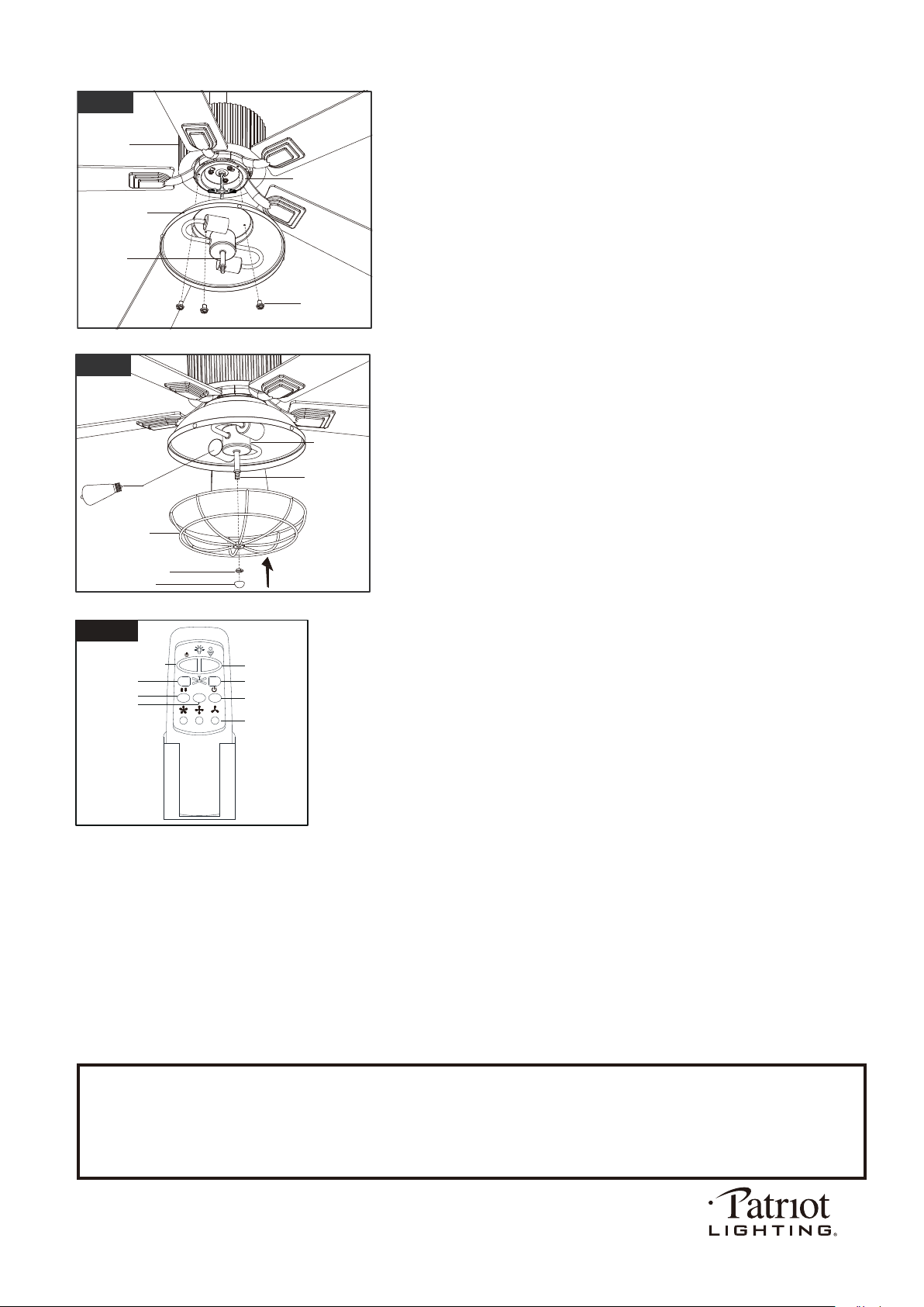
Fig.20
HI
MED
LIGHT ON/OFF
REVERSE
DIMMER
FAN OFF
LOW
TIMER
2H 4H 8H
* Press "HI" button to turn on the fan at high speed.
* Press "MED" button to turn the fan in medium speed.
* Press "LOW" button to turn the fan in low speed.
* Press "FAN OFF" button to turn off the fan.
* Press "REVERSE" button to set direction of fan rotation.
The fan speed will slow down until the fan is turned off and it will restart by spinning
in the reverse direction and resume the previously selected speed setting.
Operating transmitter:
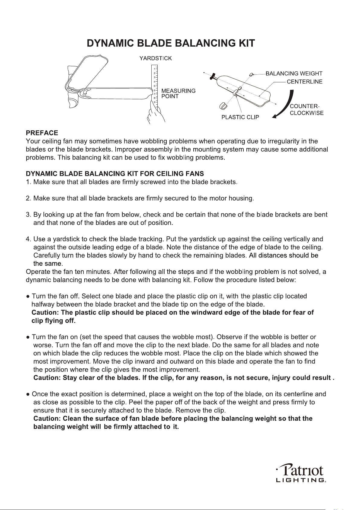
lnstall bulbs (included). See relamping label at socket area or packaging for
maximum wattage, and attach the bulbs to the light kit. Install the metal cage
upward through the threaded pipe and secure with hex nut. Then attach the
finial to the metal cage and secure it until tight.
PAGE: 8 / 12
Remove three fix screws from connect plate of light kit (for later use).
Connect the blue wire from fan motor assembly to the black wire from light kit
with a wire connector and connect the white wire from fan motor assembly
to the white wire from light kit with a wire connector. Carefully put the wires
into the connect plate of light kit, then attach the light kit onto the connect
plate of light kit with previous three fix screws.
2-6W E26 ST19 LED
Blubs Included
E26 ST19 Blubs
Max.60W
Metal Cage
Light Kit
Fig.19
Hex Nut
Finial
Threaded Pipe
* Press "LIGHT ON /OFF" button to turn on or turn off the light.
* Press and hold the "DIMMER" button to dim or brighten lights to the desired level and
release, and the brightness level will be memorized. Turn on the light again, then fan
light will be restored to the brightness-level at which it was dimmed last time.
* Timer Control:
Press "2H","4H" or "8H" "Timer" button can be set to automatically turn off the fan and
the light. If the light is off and the fan in on, the timer can automatically turn the fan off
in the selected timer time. (Same goes for the light.)
Press light off or fan off button to stop the timer control and the light or fan will be turn
off at the same time.
Note:
1. This remote controller has a memory function setting. The fan will operate at the same speed and the fan light will
stay at the same brightness-level as the last time the power supply was turned off.
2. Compatible Wall Switches: Menards SKU# 363-2615 / 363-5815 / 363-5824.
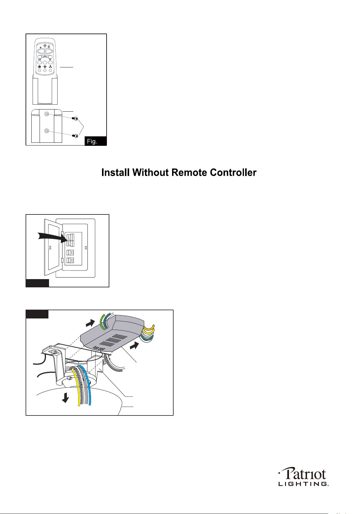
a. The direction of fan rotation can’t be set without remote controller.
b. The fan speed will be stay at high speed after remove the remote controller. Please use wall control to adjust the
speed which you need. To proceed with installation without remote control, please start from Fig.22.
3. Compatible with E26 (M) base dimmable LED bulb: Menards SKU# 353-3025.
Metal Cover
of Light Kit
Fan Motor
Assembly
Light Kit
Fix Screw
Fig.18
Connect Plate
of Light Kit
221212
Set the code:
Within the 10 second time frame after the main power is turned on, press and hold FAN OFF button for more than 3 seconds.
The LED light will begin to flash. Once the code is set successfully, the fan will turn off and the light will turn on.
Note: The included transmitter was paired with the receiver at the factory with default settings, so no need to set
the code again. Go through these setup steps if you found your transmitter can’t communicate with the
receiver.
PAGE: 9 / 12
Install the transmitter wall bracket on the wall with two screws
and place transmitter in it carefully.
Transmitter
Wall Bracket
Screw
21
2H 4H 8H
Note: Remote controller can not be used along with a solid-state speed control at the same time.
Turn OFF the electric circuit at the main fuse or circuit breaker box. (See Fig.22)
Unscrew the canopy. Remove the wire connectors from the fan
to ceiling wire connection. The receiver should be removed from
the hanger bracket. (See Fig.23)
Fig.22
Fig.23
Receiver
Canopy
Hanger Bracket
221212
.26
Connect the white (neutral)
wire and orange reversible
wire from motor to the white
(neutral) wire from the outlet
box with a wire connector.
Connect the black (hot) wire
(This is for fan control), blue wire
(This is for light control) and
yellow reversible wire from motor
to the black (hot) wire from outlet
box with a wire connector.
Bla
Black
ck
Blue
Green
White
White
Orange
Yellow
Grounding
Green
Connect three
ground wires (Green
or bare copper) coming
from outlet box,
downrod and hanging
bracket with a wire
connector.
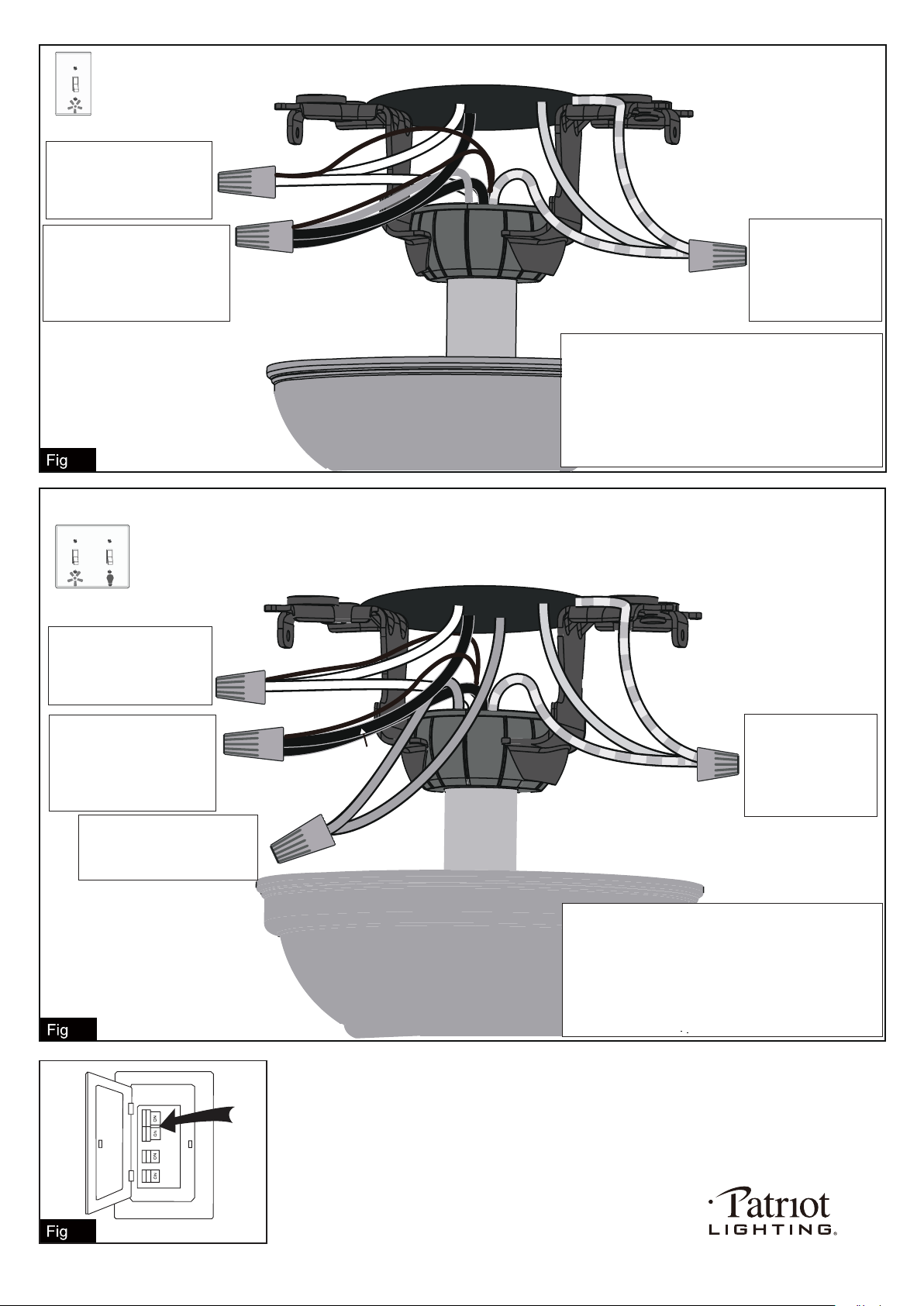
For a single switch
Follow these steps:
Connect three
ground wires (Green
or bare copper) coming
from outlet box,
downrod and hanging
bracket with a wire
connector.
Green
Black
Black
Blue
Green
White
Orange
Yellow
Blue
(light)
White
Grounding
Connect the black (hot) wire
(This is for fan control) and
yellow reversible wire from
motor to the black (hot) wire
from outlet box with a wire
connector.
Connect the white (neutral)
wire and orange reversible
wire from motor to the white
(neutral) wire from the outlet
box with a wire connector.
Connect the blue wire (This
is for light control) from motor
to the blue wire from outlet box
with a wire connector.
*** The wire connection points should be turned
upward and pushed carefully up into outlet box.
For dual switches
Follow these steps:
*** After making the wire connections, the wires should
be spread apart. The white (neutral) conductor from
motor and outlet box, orange conductor from motor
with green (grounding) conductor on one side; the
black (hot) and blue conductor from motor and outlet
box with the black, blue, yellow conductor from motor
on the other side of the outlet box.
*** After making the wire connections, the wires should
be spread apart. The white (neutral) conductor from
motor and outlet box, orange conductor from motor
with green (grounding) conductor on one side; the
black (hot) conductor from motor and outlet box
with the black, blue, yellow conductor from motor
on the other side of the outlet box.
*** The wire connection points should be turned upward
and pushed carefully up into outlet box.
.24
Turn ON the electric circuit at the main fuse or circuit breaker box.
PAGE: 10 / 12
.25
221212
2
3
4. Allow "break-in" period of 24 hours. Most noises associated with a new fan will
disappear after this period.
PAGE: 11 / 12
(not too tight)
5. If fan and light kit
do not work:
1. Replacing the battery.
2. Re-pair the transmitter and receiver by holding the " FAN OFF" button on
the transmitter according to the manual
221212
PAGE: 12 / 12
221212
