Model No.: # 355-0737
PAGE: 1 / 12
201202
11
15
2
12
13
14
7
6
5
8
9
10
3
4
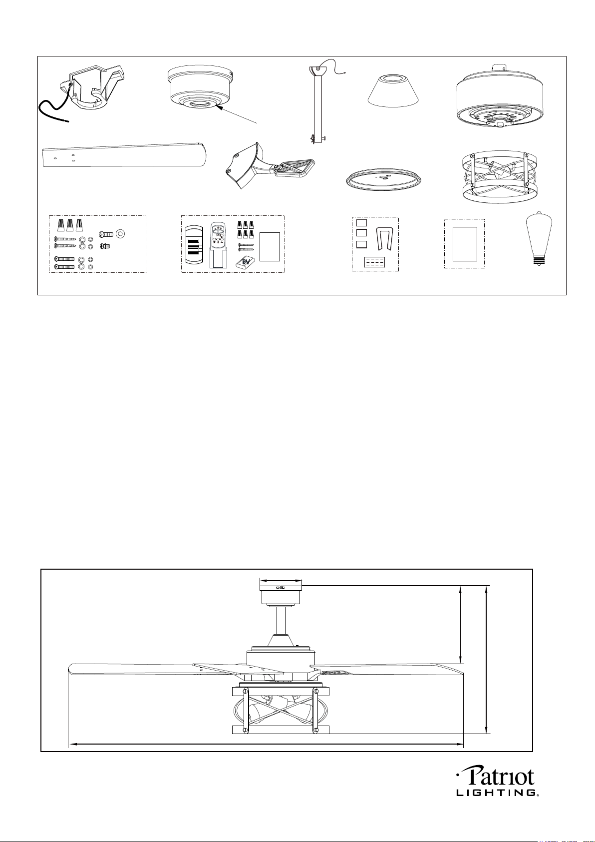
Unpack your fan and check the contents.You should have the following items.
1.) Hanger Bracket
2.) Canopy
3.) Canopy Cover
4.) Downrod Set (Included Hanger Ball, 6” Downrod, Hanger Pin & Lock Pin)
5.) Downrod Stand Cover
6.) Fan Motor Assembly
7.) Fan Blades (5 PCS)
8.) Blade Brackets (5 PCS)
9.) Connect Plate of Light Kit
10.) Light Kit
11.) Assembly Kit
12.) Remote Control Set (Includes Receiver & Transmitter & Wire Connectors & Battery
& Screws & Remote Control Instructions)
13.) Blade Balancing Kit
14.) Installation Instructions
15.) 6W E26 (M) Base ST19 Type LED Bulb (2pcs)
Package Contents:
1
Installation
Instructions
Remote
Control
Instructions
X 16
Dimension Reference (Installed with 6” Downrod):
A. 18-5/8” B. 10-7/8” C.52” D. 5-1/8”
C
A
B
D
PAGE: 2 / 12
201202
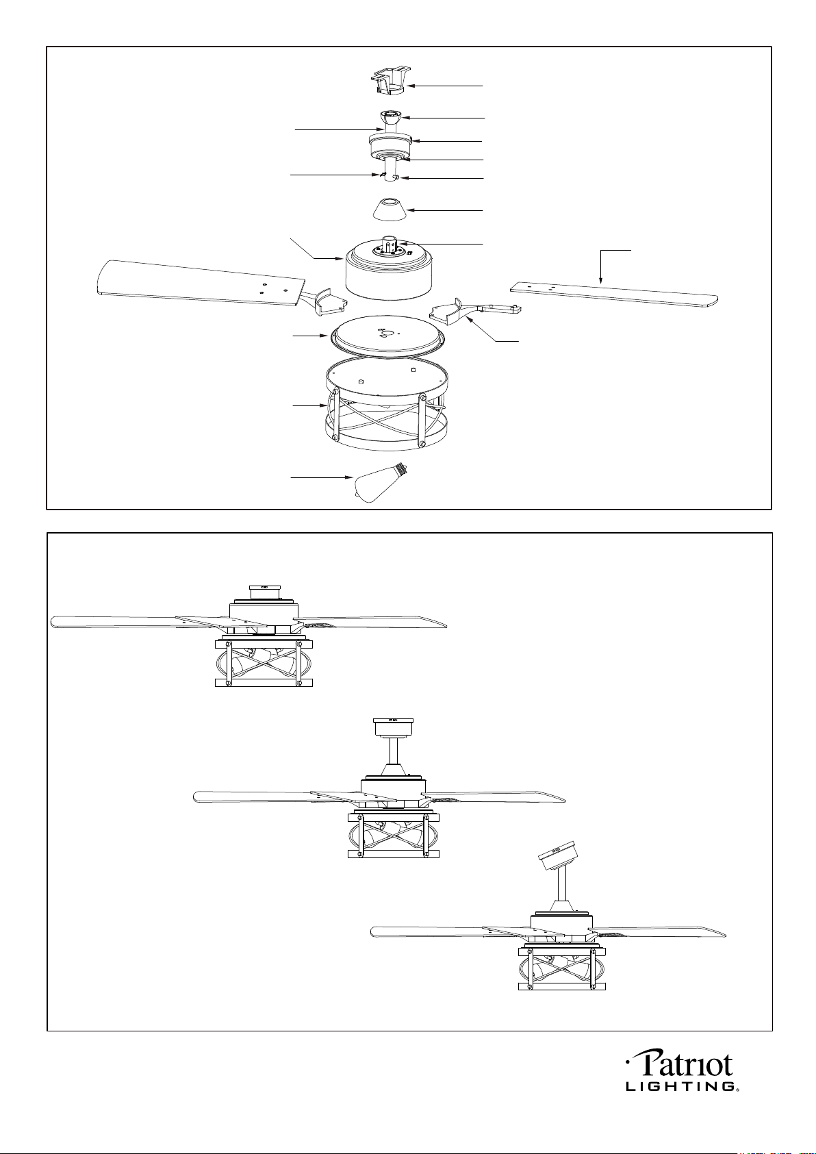
Exploded View Detail
Hanger Bracket
Hanger Ball
Canopy
Canopy Cover
Hang Pin
Downrod Stand Cover
Collar
Blade Bracket
Fan Blade
Downrod
Lock Pin
Connect Plate of Light Kit
Light Kit
LED Bulb
Fan Motor Assembly
Triple Mount Options
Ceiling Mount
Downrod Mount
Slope Ceiling Mount ( Up to 23 degrees)
PAGE: 3 / 12
201202
PAGE: 4 / 12
201202
NOTE: The fan weight is 18.52 lbs (8.4 kg). Be sure the outlet box you are using is securely attached to the building
structure and can support the full weight of the fan. Failing to do so can result in serious injury.
INSTALLATION INSTRUCTIONS
IMPORTANT:
BEFORE YOU BEGIN INSTALLING THE FAN, CAREFULLY READ ALL INFORMATION IN
SAVE ALL INSTRUCTIONS.
Hanger Pin
Lock Pin
Fig.5
Installation Steps :
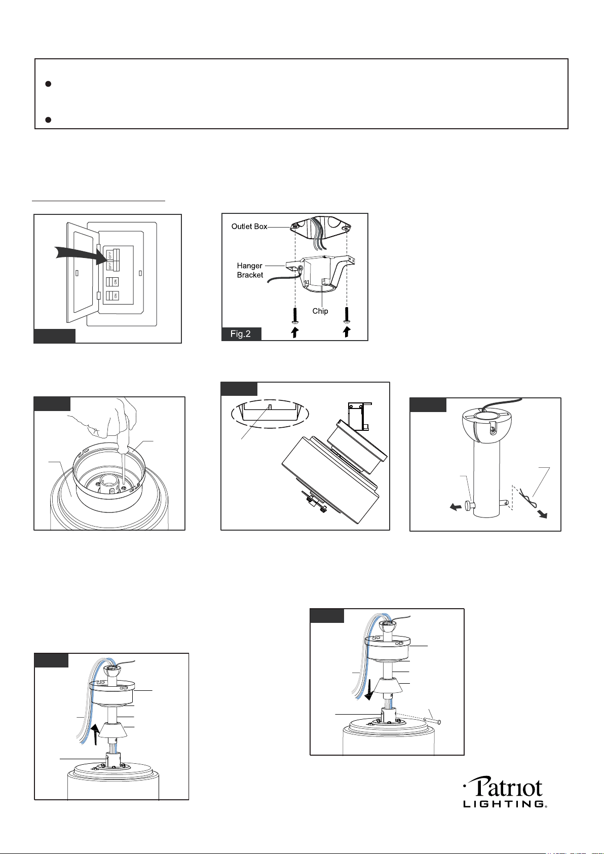
Fig.1
Turn OFF the electric circuit at the
main fuse or circuit breaker box.
THE SAFETY
INSTRUCTIONS AND INSTALLATION INSTRUCTIONS. IF IN DOUBT, CONSULT A QUALIFIED
ELECTRICIAN.
Canopy
Canopy Cover
Downrod Stand
Cover
Downrod Motor Wires
Collar
Fig.6
(For downrod mount only):
Thread the motor wires
through the downrod stand
cover, decorative cap
(Making sure the smooth
side of decorative cap is
facing downward.),
canopy and downrod.
Tighten the hanger bracket to the outlet
box with two mounting screws. (To reduce
the risk of fire, electric shock, or personal
injury, mount to an outlet box marked
"Acceptable for fan support" and use
mounting screws provided with the outlet
box.)
Note: For slope ceiling installation, make
sure that the chip of the hanger bracket
is toward the floor.
(For
downrod
mount only):
Remove the lock pin and take off
the hanger pin.
(For downrod mount only):
Loosen the collar screws
out part way.Insert the
downrod into the collar.
Slide hanger pin through
holes of collar and downrod.
Canopy
Canopy Cover
Downrod Stand
Cover
Downrod
Motor Wires
Collar
Hanger Pin
Fig.7
Fig.3
Canopy
Housing
Fig.4
Hanger Bracket
Hook
(For ceiling mount only):
Remove the canopy cover from the
canopy.
Remove downrod stand cover and
three of six screws (every other one)
securing the motor collar to the top
of the fan motor housing. Attach the
canopy to the housing with three screws.
(
For ceiling mount only):
Raise the fan and place the canopy
on the hanger bracket hook for wiring.
Go to Fig.10 for the next steps.
PAGE: 5 / 12
201202
PAGE: 6 / 12
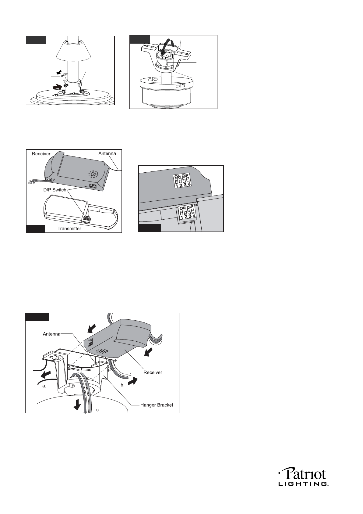
Move ground wires (a), outlet box wires (b), and motor
wires (c) away from the center of the hanger bracket.
Then slide receiver through hanger bracket as shown.
Antenna end first, until it is centered. Finally, cut motor
wires (c) to length needed for connections.
Fig.10
Code example:
1-ON 2-OFF 3-ON 4-OFF on both DIP
Switches.
Note: If you have two ceiling fans with
2 remote control units, set 2 different
codes for each set of transmitter / receiver.
Fig.10a
(For downrod mount only):
Hang the fan on hanger bracket, and
make sure the slot of hanger ball is
snapped into the chip of hanger
bracket exactly.
Note: For slope ceiling installation,
make sure the slot of hanger ball and
the chip of hanger bracket face down.
(For downrod mount only):
Tighten the two collar screws.
Slide lock pin into hanger pin until
it is locked into position.
Fig.8
Lock Pin
Collar Screws
Fig.9
Slot
Chip
Hanger Bracket
There is a code switch in the transmitter
and receiver. This "DIP Switch" is a 4 key
unit (Fig.10). All keys were set at "ON"
position in the beginning. Set the keys to
a different code. Make sure the same
numbered keys are switched "ON" for
both DIP Switches (Fig.10a). Take note
that the "ON" position may have different
orientation in each.
Fig.11
201202
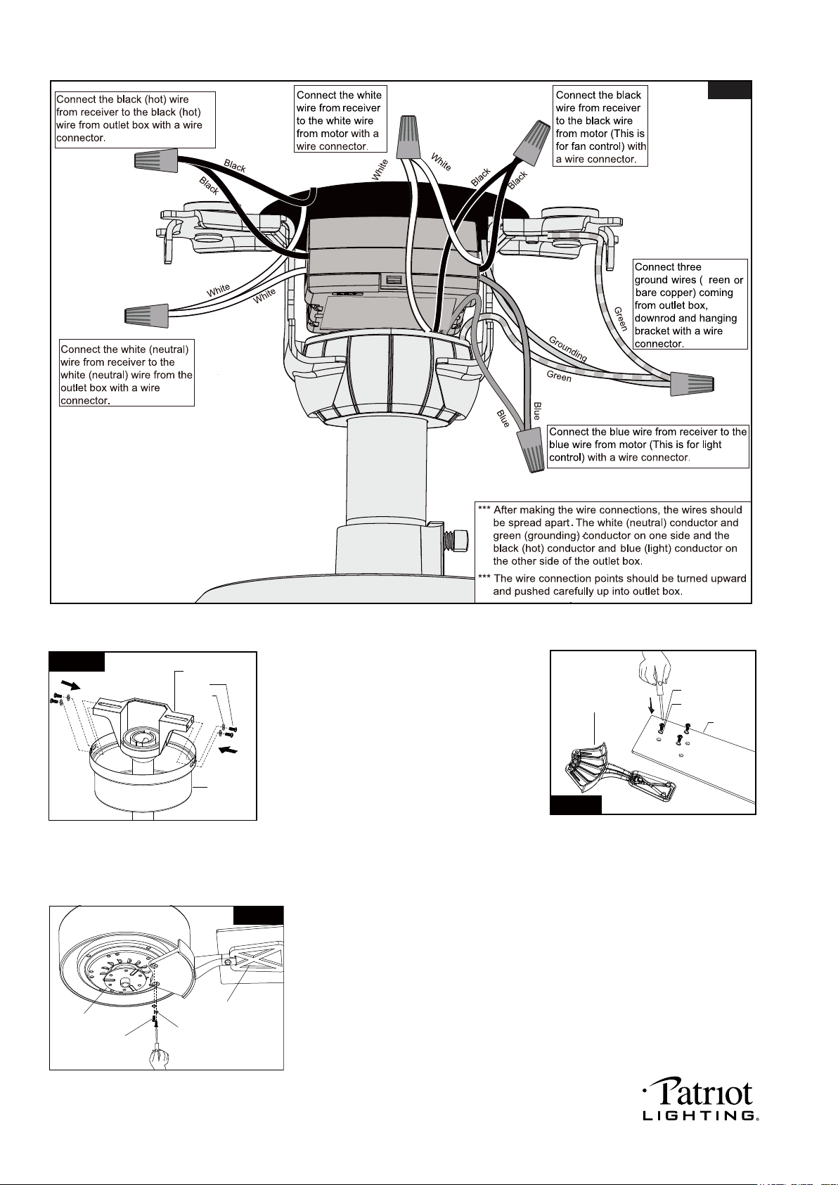
Tighten blades to blade brackets by
using blade screws and washers.
Remove the motor screws and washers
from the fan motor assembly.
Secure blade brackets to the motor with
washers and motor screws.
Note: Making sure the smooth side
of blade bracket is facing downward.
G
Fig.12
Canopy
Washer
Screw
Hang Bracket
Fig.13
Blade Screw
Blade Bracket
Blade
Washer
Fig.14
Fig.15
Motor Screws
Washer
Blade Bracket
Motor
There are four hanger bracket screws and
lock washers. Remove two screws and lock
washers from the hanger bracket (one from
each side) and loosen the other two
remaining screws. Align the “L shaped” slots
of the canopy with the two remaining screws
on the hanger bracket and push the canopy
upwards to engage the slots and turn
clockwise to lock in place. Tighten the
screws and install the other two hanger
bracket screws and lock washers into the
remaining holes of the canopy and tighten.
PAGE: 7 / 12
201202
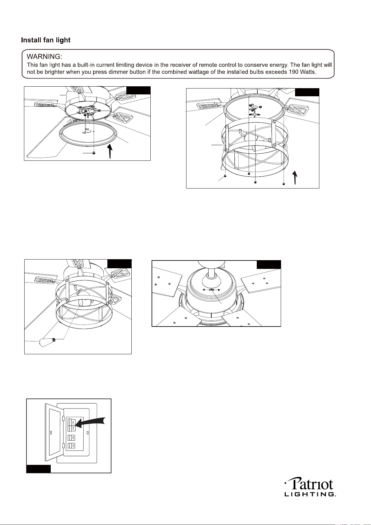
Fan Motor
Assembly Screw
Fan Motor Assembly
Connect Plate of
Light Kit
Fig.16
Fig.17
Light Kit
Slide Switch
Forward
Severse
Fig.19
Remove one screw and loosen another two screws
from fan motor assembly first, thread the fan motor
assembly wires through connect plate of light kit
then push the connect plate of light kit upwards
until the fan motor assembly screws insert into
the key hole slots of connect plate of light kit then
rotate the connect plate of light kit until it’s fixed
on the fan motor assembly bottom. Finally, secure
the connect plate of light kit to the fan motor assembly
bottom with previous screw which was removed.
Tighten the other two fan motor assembly screws.
Remove four connect plate screws from connect
plate of light kit first. Then connect the white (neutral)
wire from the light kit to white (neutral) wire from connect
plate of light kit with a wire connector; connect the black
(hot) wire from light kit to blue (hot) wire from connect
plate of light kit with a wire connector. Carefully put the
wires into the connect plate of light kit , then attach the
light kit onto the connect plate of light kit with the connect
plate screws.
Install LED bulbs (included).
See relamping label at socket area or
packaging for maximum allowed wattage.
Connect Plate
of Light Kit
Connect Plate Screws
The slide switch on fan motor assembly sets
direction of fan rotation. Select the desired
direction of fan rotation. Push the slide switch
left for "Forward" and right for "Reverse".
Note: Wait for fan to stop before reversing the
direction of blade rotation.
Fig.18
2-6W E26 ST19 LED Blubs Included
E26 ST19 Blubs Max.60W
Fig.20
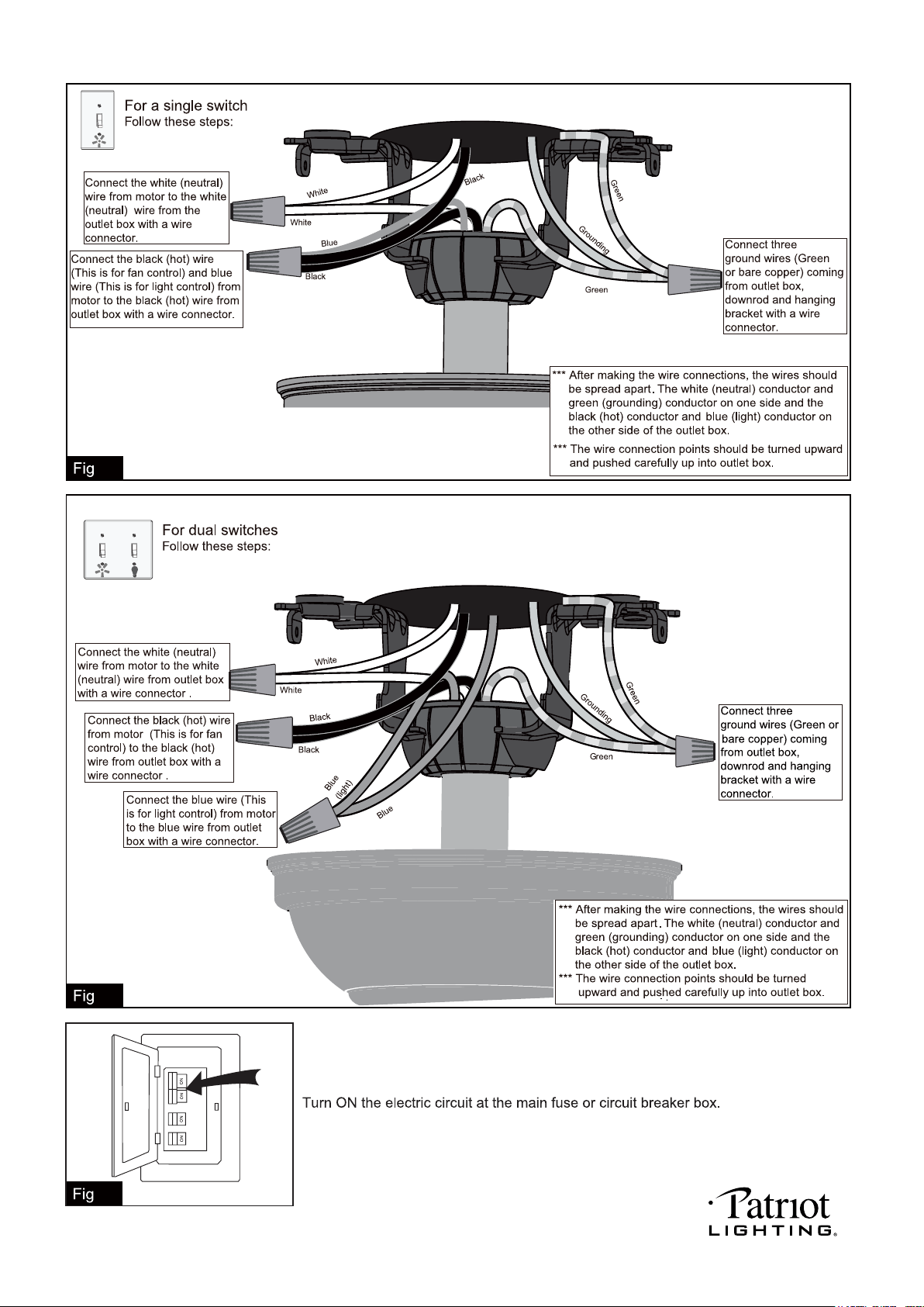
Turn ON the electric power at the
main fuse or circuit breaker box.
PAGE: 8 / 12
201202
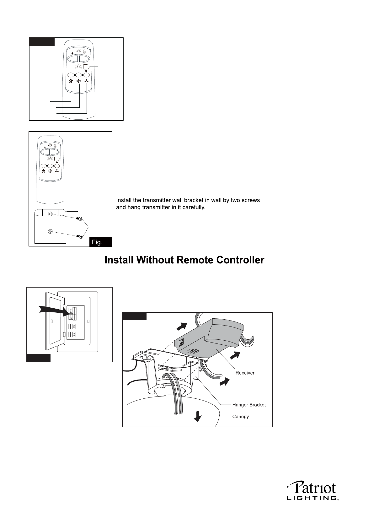
Note: Remote controller can not be worked along with solid-state speed control at the same time.
Turn OFF the electric circuit at the main fuse or circuit breaker box. (See Fig.23)
Unscrew the canopy. Remove the wire connectors from the fan to ceiling
wire connection. The receiver should be removed from the hanger bracket.
(See Fig.24)
Fig.21
HI
MED
LIGHT
0N/0FF
DIMMER
FAN OFF
LOW
Install the battery (9V, included) to the transmitter.
* Press "HI" button to turn on the fan at high speed.
* Press "MED" button to turn the fan in medium speed.
* Press "LOW" button to turn the fan in low speed.
* Press "FAN OFF" button to turn off the fan.
* Press "LIGHT ON /OFF" button to turn on or turn off the light.
* Press and hold the "DIMMER" button to dim or brighten lights to the desired level and
release, and the brightness level will be memorized.Turn on the light again, then fan
light will restore on of the brightness level which was dimmed last time.
Note:
1. This remote controller has memory function setting. The fan will operate at the same
speed and the fan light will stay at the same brightness as the last time the power supply
was turned off.
2. Compatible wall switch model No.: Menards SKU# 3632615 / 3635815 / 3635824.
3. Compatible with E26 (M) base dimmable LED bulbs model No.: Menards SKU# 3537322.
Transmitter
Wall Bracket
Screw
22
Fig.23
Fig.24
PAGE: 9 / 12
201202
.25
.26
.27
PAGE: 10 / 12
201202
PAGE: 11 / 12
201202
PAGE: 12 / 12
201202
