Questions, problems, missing parts?
Before returning to your retailer, call our customer service at 1-800-887-6326
Monday – Friday 9:00 a.m. – 5:00 p.m. CST
Page 1 of 17
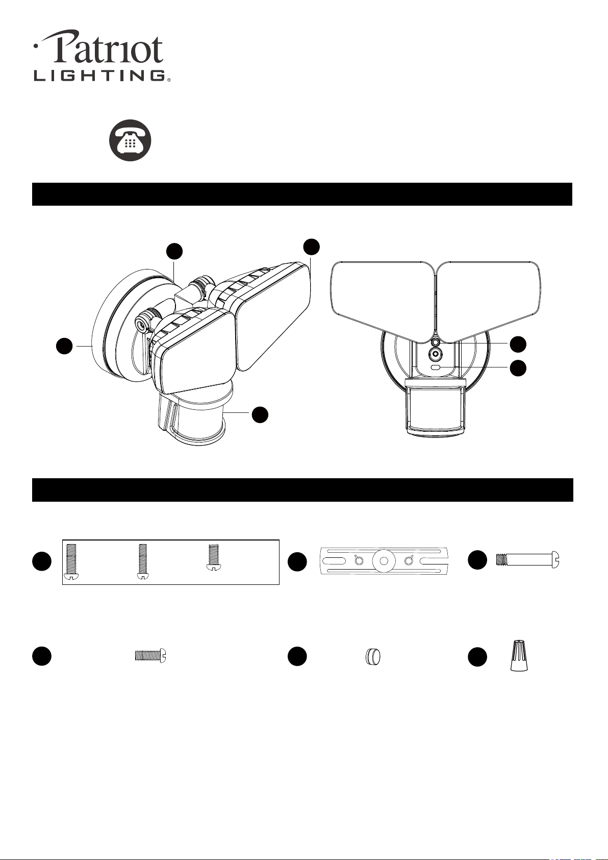
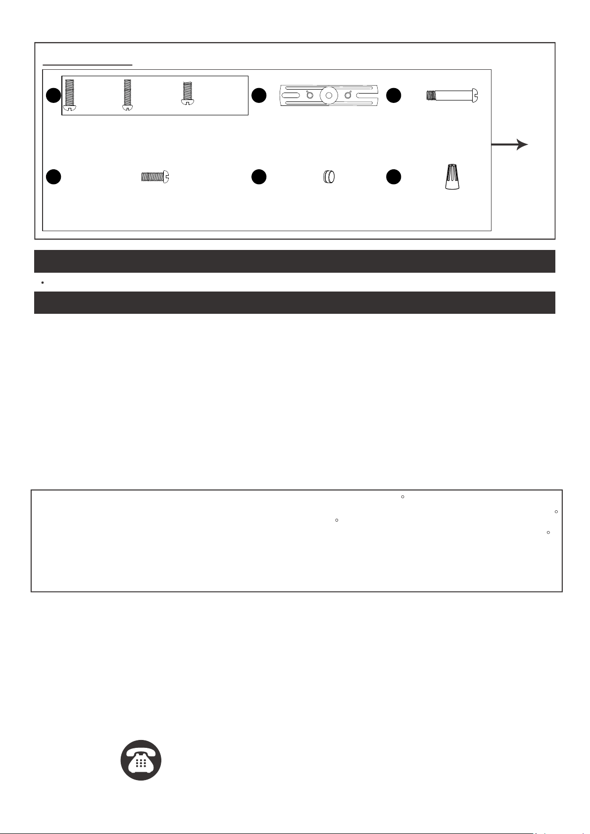
PACKAGE CONTENTS
Sku Number: 356-9258
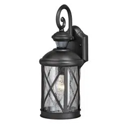
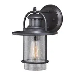
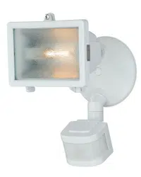
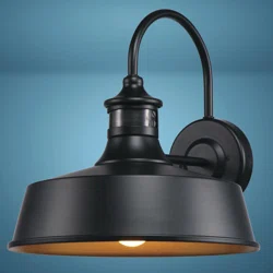
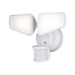
OUTDOOR SECURITY LIGHT
Model Number: E8197W
HARDWARE CONTENTS Note: Hardware not shown actual size.
AA
BB
DD
CC
EE
Mounting Screw
X2
Mounting Bracket Screw
X1
Fixture Mounting Screw
X1
Mounting Strap
X1
FF
Wire Connector
X2
Decorative cover
X1
#8/32 X 1/2 in
#6/32 X 1/2 in
#10/24 X 1/4 in
191011
A
B
D
E
F
C

SAFETY INFORMATION
PREPARATION
Before beginning assembly, installation or operation of product, make sure all parts are present. Compare parts with
package contents list and diagram on previous page. If any part is missing or damaged, do not attempt to assemble,
install or operate the product. Contact customer service for replacement parts.
Page 2 of 17
Please read and understand this entire manual before attempting to assemble, operate or install the product.
WARNING
• Turn off electricity at main fuse box (or circuit breaker box) before beginning installation by removing fuse (or switching
off circuit breaker).
• Be careful not to damage or cut the wire insulation (covering) during fixture installation. Do not permit wires to contact
any surface having a sharp edge. To do so may damage or cut the wire insulation, which could cause serious injury
or death from electric shock.
• LED electronics can be damaged by electro static discharge (ESD)shock. Before installation, discharge yourself by
touching a grounded bare metal surface to remove this hazard. To avoid damage, do not touch the LED module.
CAUTION
• All electrical connections must be in agreement with local codes, ordinances or the national electric code (NEC).
Contact your municipal building department to learn about your local codes, permits and/or inspections.
• Risk of fire – most dwellings built before 1985 have supply wire rated for 140°F/60ºC. Consult a qualified electrician
before installation.
• Only general ON/OFF wall switch applies for this fixture, the dimmable wall switch shouldn’t be required.
Maximum Wattage: 32 W
Working Temperature Range: -4ºF ~ 113ºF
Tools Required for Assembly (not included): Screwdriver, Phillips Screwdriver, Pliers, Electrical Tape, Wire Cutters,
Safety Glasses, Ladder, Wire Stripper.
ASSEMBLY INSTRUCTIONS
Important to Know
1. This fixture requires a 120 VAC, 60 Hz power source.
2. For general safety and to avoid any possible damage to the sensor, be sure the power is switched "off" before
adjustment.
3. Motion sensor: turns light ON automatically when motion is detected and turns light OFF automatically when motion
stops.
4. Photocell keeps the light OFF during daylight hours.
Note: Fixture can be wall mounted or eave mounted.
Wall Mounted
Light fixture and sensor should be mounted as shown above when installed (depending upon type of installation)
Before installing the light fixture under an eave, the sensor head must be rotated as shown in the next two steps for
proper operation and to avoid the risk of electrical shock.
Eave Mounted
191011

Page 3 of 17
ASSEMBLY INSTRUCTIONS (continued)
For eave mounted only:
Swing the sensor head towards the mounting bracket.
Controls
Mounting Bracket
Controls
Controls
Turn off the power at fuse or circuit box.
1. The fixture mounting bracket
(A) is pre-assembled on the
light fixture (B). Unscrew both
the decorative cover (DD)
and the fixture mounting
screw (EE) in order to remove
the mounting bracket (A).
2. Install the mounting strap
(CC) to the outlet box with
the stamped word “FRONT”
facing away from the outlet
box, using two mounting
screws (AA) that best fit the
outlet box. Mounting bracket
(A) should sit flush against
wall surface when secured.
(Choose one matching pair of suitable mounting screws
(AA) from the 3 pairs provided).
2
FRONT
CC
AA
A
3. Pull out the source wires from
the outlet box. Make wire
connections using wire
connectors (FF) as follows:
---Connect the black wire from
the fixture to the “hot” wire
from the power source.
---Connect the white wire from
the fixture to the neutral wire
from the power source.
Carefully tuck the wires back into the outlet box.
4. Place mounting bracket (A)
against the outlet box, insert
the mounting bracket screw
(BB) through the mounting
bracket hole, thread mounting
bracket screw (BB) into the
center hole of the mounting
strap(CC). Tighten the
mounting bracket screw (BB)
securely.
When mounting to a wall, the “UP” arrow must point
upward.
When mounting to an eave, the “UP” arrow must point
toward the building.
5. Attach the backplate(B) of the
light fixture to the mounting
bracket(A), secure it with the
fixture mounting screw(EE).
Then push the decorative
cover (DD) firmly into the
fixture mounting screw (EE)
hole on the light fixture.
6. With silicone caulking
compound, caulk
completely around where
the mounting bracket meets
the wall surface.
CAUTION: Be sure to
caulk completely where
the mounting bracket
meets the wall surface to
prevent water from
seeping into the outlet box.
Outlet Box
3
FF
4
FF
BB
A
CC
Outlet Box
6
1
A
B
DD
EE
5
A
B
DD
EE
Turn on the power at fuse or circuit box.
Ensure the indicator (E) is blinking red light.
If not, please press and hold the reset button (F) for 10 second and release to activate red light blinking.
191011

Adjusting the Sensor Head:
1. a: Aim sensor head (D) toward desired detection area, maintaining a 5° - 40° downward angle
to allow moisture to drain. (See Fig.1)
Note: Make sure sensor head is positioned with control knob facing towards the ground.
b: You can adjust the sensor head up and down to change the coverage area. Walk through
the detection zone at the farthest distance you wish to detect motion.
D
Adjustment Sensor Lower For Short Coverage
A
d
j
u
s
t
m
e
n
t
S
e
n
s
o
r
H
i
g
h
e
r
F
o
r
L
o
n
g
C
o
v
e
r
a
g
e
Fig.2-1
Fig.2-2
Fig.1
2. Range set too high may increase false triggering.
(See Fig.2-1, 2-2)
Fig.3
1. Gently grasp the light heads(C) and tilt them down, left or right to adjust the light
coverage area. Keep the light heads at least 1” (25mm) away from the sensor.
(See Fig.3)
Adjusting the Light Head:
C
ASSEMBLY INSTRUCTIONS (continued)
Page 4 of 17
191011
Sensitivity of Motion Sensor:
Fig. 4
Mode Sens Time
6H
Auto
3H
PC
L
M
H
Test
30s
3 min
1min
1. You can adjust the sensitivity of the motion sensor by using the “Sens” selector
located on the bottom surface of the sensor. (See Fig.4)
2. Adjust motion sensor sensitivity to HIGH (H), MEDIUM (M), or LOW (L) to achieve
desired performance.
3. Approximate range for each setting: 25 ft. (L), 45 ft. (M), 70 ft. (H).
Choose a mode by sliding the switch on the bottom of the sensor. (See Fig.4)
Note: When power is first applied, the light will turn on to 100% brightness.
The sensor will take 30 seconds to warm up.
1. TEST mode (daytime or nighttime operation ) (See Fig.4)
Then turns the light off about 5 seconds after motion is no longer detected.
2. AUTO MODE (nighttime operation only) (See Fig.4)
(30s/1min/3min). At dusk, the light turns on to low level brightness. When motion is detected, the light turns to full
brightness and stays on as long as motion continues. When the motion is no longer detected, the light stays on
high-level brightness for the predetermined time you set (30s/1min/3min), and then switches back to low level
automatically.
3. 3 HOURS (3H) MODE (nighttime operation only) (See Fig.4)
stays on as long as motion continues. When motion is no longer detected, it remains on for the predetermined
shut-off delay time you set (30s/1min/3min), and then returns to the low-level brightness automatically.
4. 6 HOURS (6H) MODE (nighttime operation only) (See Fig.4)
stays on as long as motion continues. When motion is no longer detected, it remains on for the predetermined
shut-off delay time you set (30s/1min/3min), and then returns to the low-level brightness automatically.

Page 5 of 17
ASSEMBLY INSTRUCTIONS (continued)
ASSEMBLY INSTRUCTIONS (continued)
5. To reduce possible nuisances, do not mount the fixture
near a heat source like an air conditioner, vent or furnace
exhaust, or in a direction facing any reflecting object or other
light source.
25'
8.0'
12.0'
70'
Where you install your fixture is important:
Be sure the light is mounted straight on the wall
or eave; otherwise, the detection distance may
be limited.
Fig. 6
Fig. 7
Motion
Least sensitive
Motion
Most sensitive
Sensor
Fig. 8
240'
Notes:
1. The sensitivity of the motion sensor will increase as the
environmental temperature gets cooler. You may wish to
make adjustments when the season changes.
For best performance, gently clean the lens with a soft
cloth every 1 or 2 months to assure maximum sensitivity.
2. For best performance, install fixture at least 8 feet above
the ground. At such a height, the fixture will provide a
detection distance of up to 70 feet at 77 degrees
Fahrenheit. (See Fig.6)
3. The sensor detects movement across a detection range
of 240 degrees. (See Fig.7)
4. The sensor will be more sensitive to motion across its
detection path than motion directly towards it. (See Fig.8)
FUNCTION AND OPERATION
ASSEMBLY INSTRUCTIONS (continued)
ASSEMBLY INSTRUCTIONS (continued)
Hardware Information of the Product
191011
5. PHOTOCELL (PC) MODE (nighttime operation only) (See Fig.4)
6. 3Min/10Min dual timer
continue to stay on for 10min and so on.
Indicator Light
1. Green light flash. Smart link mode.
2. Green light slowly flash. AP mode.
3. Blue light flash. Connected to router but not internet signal.
4. Blue light. Connected to the internet with internet signal.
5. Red light flash. Factory reset mode.
Reset Button
1. Press twice within 5 seconds. Smart link mode.
2. Press and hold for 5 seconds then release.
AP mode.
3. Press and hold for 10 seconds then release.
Factory reset mode.

Page 6 of 17
USER GUIDE
1. Search "DualuxBT" in IOS APP
store or "Dualux" in Android
Google Play. Install the Dualux
APP onto the device.
It’s available for Apple and
Android device.
3. Click “Register” for new accounts
or “Login” for existing accounts.
5. Enter verification code and
set password,then click
register.
6. Click “Search for lights”.
4. Enter E-Mail address,
then click “Next”.
2. Start the App and click
“WIFI”.
Se ng for single light through mobile device (Take iOS for example as below. Android will
be slightly di erent).
Before you start
191011
1
9:41 AM
Back
Take photo
Choose existing photo
Cancel
6
9:41 AM
Back
Take photo
Choose existing photo
Cancel
2
9:41 AM
Back
Take photo
Choose existing photo
Cancel
3
9:41 AM
Back
Take photo
Choose existing photo
Cancel
4
9:41 AM
Back
Take photo
Choose existing photo
Cancel
5

Page 7 of 17
USER GUIDE (continued)
7. Follow the step 1, 2, 3 show
in the phone, then click “next”.
9. The status window will
appear once the device(s)
have successfully connected
and the 3 bullets point on the
bottom will follow by a tick.
Note: If unsuccessful, the
“Failed to Add” screen will
appear. Close the App and
repeat the previous steps,
or connect to WiFi in AP
mode (9.1~9.5).
AP mode setup steps (9.1~9.5).
9.1 In Fig.7 click “ AP mode”
(In the upper right corner).
Follow the step 1, 2, 3, 4
show in the phone, then click
“next”.
8. Choose a 2.4GHz WiFi
network and enter the WiFi
password, then click
“Confirm”.
Note: Only works with
2.4GHz WiFi networks.
191011
9:41 AM
Back
Take photo
Choose existing photo
Cancel
7
9:41 AM
Back
Take photo
Choose existing photo
Cancel
8
9:41 AM
Back
Take photo
Choose existing photo
Cancel
9
9.2 Choose a 2.4GHz WiFi
network and enter the WiFi
password, then click
“Confirm”.
Note: Only works with
2.4GHz WiFi networks.
9.3 Connected to the lighting
devices “WiFi (HF-XXXXXX)”.
Click “Set Wi-Fi”
9:41 AM
Back
Take photo
Choose existing photo
Cancel
9.2
9:41 AM
Back
Take photo
Choose existing photo
Cancel
9.3
9:41 AM
Back
Take photo
Choose existing photo
Cancel
9.1
slowly

USER GUIDE (continued)
12. The Setting list, You can set
up “Functions”, “Change
image”, “Rename light”, and
“Restore factory defaults”.
11. The new light will be shown
in light list. And click“ ”
icon, it will go to the
setting list.
9:41 AM
Back
Take photo
Choose existing photo
Cancel
10-2
9.5 The status window will
appear once the device(s)
have successfully connected
and the 3 bullets point on the
bottom will follow by a tick.
10. Successfully added device, then click “confirm”.(See Fig10-1)
If you want to rename, click the “modify device name”,
enter the new name and save.(See Fig10-2)
The light is now ready to be controlled with the dualux App.
Page 8 of 17
191011
9:41 AM
Back
Take photo
Choose existing photo
Cancel
9.4-2
9.4-1
9:41 AM
Back
Take photo
Choose existing photo
Cancel
9.4 Choose a “HF-XXXXXX” WiFi to connect. (See Fig 9.4-1)
then click “ ” to return. (See Fig 9.4-2)
9:41 AM
Back
Take photo
Choose existing photo
Cancel
12
9:41 AM
Back
Take photo
Choose existing photo
Cancel
10-1
9.5
9:41 AM
Back
Take photo
Choose existing photo
Cancel
11
Security Light
16. In Fig.13 “Change image”.
And click “ take photo ” to
take a photo.
Page 9 of 17
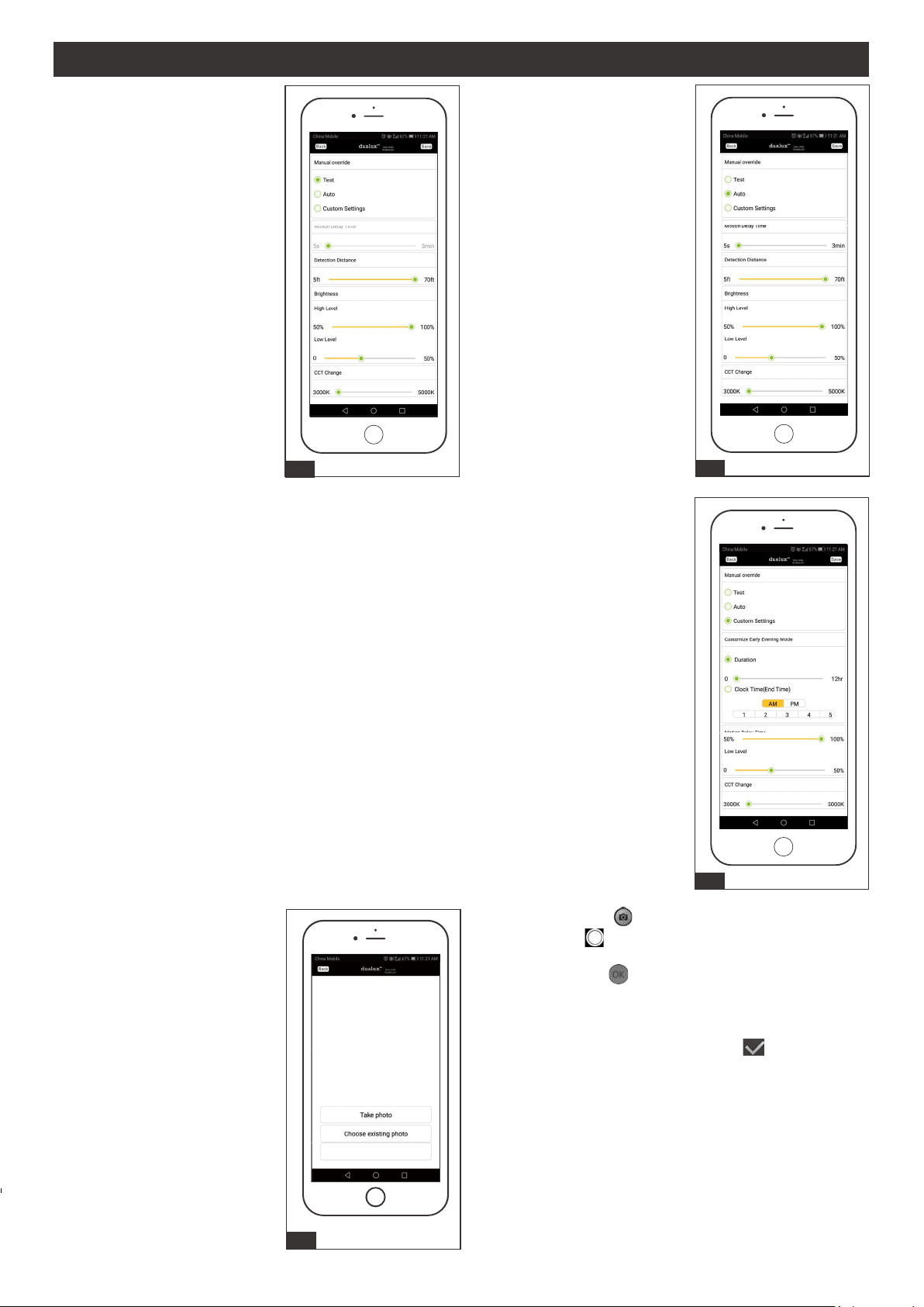
13. Click the “Functions”, You
can choose “Test”, “Auto”,
or “Custom Setting”.
Select “Test” in Manual
override and adjust
“Detection Distance” ,
“Brightness” and “CCT
change” as desired.
Then click “Save”.
14. Select “Auto” in Manual
override and adjust “Motion
Delay Time”, “Detection
Distance” , “Brightness” and
“CCT change” as desired.
Then click “Save”.
15. Select “Custom Settings” in Manual Override for Customize Early Evening Mode setting
and choose option between “Duration” or “Clock Time (End Time)” to set the continuous
bright light illumination duration. Within “Duration”, you may set from 0 to 12 hours for
continuous bright light once lamp is activated at night. In “Clock Time (End Time)”, is the
time you set to deactivate the continuous bright light according to the actual hour in the
mobile device after the lamp is activated. Both option settings will return to motion-sensor
operation after the continuous bright light is deactivate. 9:00 P.M. is the default in “Clock
Time (End Time)”.
Note: "Duration" setting will only work once per setting, it automatically go into
“Clock Time (End Time) on the next day. Also if you do not click save for either
option, then the settings will follow according to the switch control on the actual
lamp.
a. Android: Click “ ” to grasp a your desired view.
IOS: Click “ ” to grasp a your desired view.
b. Android:Click “ ” to take a photo.
The iOS system does not have this step.
c. Android: Adjust the photo to trim the photo's
"desired size. Then click “ ” .
IOS: Click“Done” to take a photo.
191011
13
16
Cancel
14
15
USER GUIDE (continued)

Page 10 of 17
17. It will turn to “change image”.
The photo will show on it.
(Android will be slightly different
from the iOS system)
17
18. Go back to “Light list”, the
photo will show on the
left of “Light 1”.
18
19. Click “choose existing photo”
to choose a desired image on
your device. Then click
“Cancel” back to “Setting”
menu list.
20. Click Fig.13 “Rename light”
to enter a name for the
light, then click “Save”.
20
21. Click "Remove light" to remove
the device from the light list.
If you want to reconnect the
light, press "reset button" twice
within 5 seconds.
Note: 1. Manual control and App control
independently.
2. The function will execute the last
settings.
3. For achieving the best performance,
make sure the wall switch is in “ON”
state (daytime and nighttime).
191011
USER GUIDE (continued)
21
Remove light
Rename light
Change image
Functions
19
Cancel

USER GUIDE (continued)
Page 11 of 17
191011
Manual Override Daytime:
During day time, when you say “Turn On Security light”, the light will turn on and stay
on all day, and then go into Auto Mode during dusk.
Manual Override Nighttime:
During nighttime, when you say “Turn On Security light”, the light will turn on and stay
on. The light will then turn off at dawn, and go into Auto Mode during the next dusk.
CCT Color Change:
When the light is on, you may adjust the CCT Color by saying “Set Security light
Warmer (or Cooler)” or you may say “Set Security light to Warm White (or Daylight)”.
Adjust High Level Brightness:
Anytime when you say “turn on security light”, after the light turns on, you may adjust
“brighten (or dim) security light”. Then say “turn off security light” to confirm you
High Level Brightness setting.
Adjust Low Level Brightness:
Anytime when you say “turn off security light”, after the light turn off, you may adjust
“brighten (or dim) security light”. Then say “turn off security light” to confirm your Low
Level Brightness setting.
If the light fixture Mode setting was 3H/6H/PC (Set on light fixture or App), after
complete voice control setting, the light will automatically switch to Auto mode.
Voice Command Control
Page 12 of 17
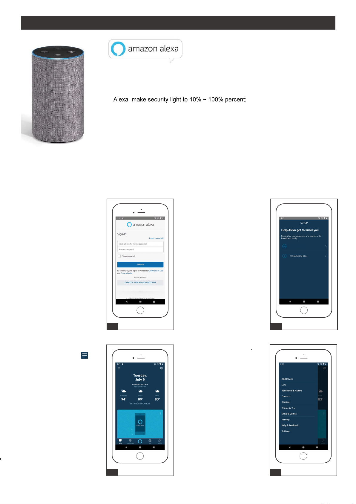
Connecting to Alexa
1. Search "Amazon Alexa"
in Google Play or Apps
Store to download
Amazon Alexa App and
complete sign in.
2. Select your name or
someone else.
191011
1
4. Select Skills & Games
3 4
Smarter More Helpful Home Security Light That Work with Alexa Control lighting with
simple voice commands.
Adjust brightness:
Alexa, turn on/off security light;
Alexa, brighten/increase security light;
Alexa, dim/decrease security light.
Adjust color temperature:
Alexa, make security light warmer;
Alexa, make security light cooler;
Alexa, make security light to warm white;
Alexa, make security light to soft white;
Alexa, make security light to white;
Alexa, make security light to daylight white
3. Start the Alexa App then
click on the “Menu” .
(In the upper left corner)
2
I'm user
USER GUIDE (continued)

Page 13 of 17
191011
10. Discover devices for 20
seconds
9. In Fig 9, click "discover
device".
9
4
10
5. In the search menu type
“Innovation & Perfect”. then
click “Innovation & Perfect”.
6. Click “ENABLE TO USE”.
8. Once successful linked
page appear, click upper
left "X ".
7. Enter the same user name
& password that you have
registered under the dualux
App. Then click “Login”.
5 6
7
4
8
USER GUIDE (continued)

Page 14 of 17
191011
13. Select a group. 14. Light is added to a group.
12. Add your light to a group.11. When light is discovered
click "set up device".
11
4
12
13
4
14
Security Light added to Living
Room
15. Click "lights". 16. New device is displayed
in group.
15
4
16
Security Ligh t
USER GUIDE (continued)

Page 15 of 17
191011
Connecting to Google Home
2. Click set up device.
1 2
1. Search "Google Home" in
Google Play or App Store to
download Google Home App
and complete sign in.
Smarter More Helpful Home Security Light That Work with Google
Home Control lighting with simple voice commands.
Adjust brightness:
Hi, Google, turn on/off security light;
Hi, Google, brighten/increase security light;
Hi, Google, dim/decrease security light.
Adjust color temperature:
Hi, Google, make security light to warm white;
Hi, Google, make security light to soft white;
Hi, Google, make security light to white;
Hi, Google, make security light to daylight white.
3. Select Works with Google
4. Select Innovation & Perfect.
3 4
Innovation & Perfect
USER GUIDE (continued)

Page 16 of 17
191011
5. Enter the same user name
& password that you have
registered under the dualux
App.
7. Go back to main page. 8. A device links to google
home automatically.
6. Wait for signing in.
5 6
7 8
Security Light
Range
Up to 70ft. (Varies with surrounding
temperature)
Up to 240º
32W
2600lm
120 VAC, 60Hz
Test, Auto, 3H, 6H, PC
30s,1min,3min
Iphone 4S or newer running IOS 10.0 x or later.
Android v6.0 or later
Sensing angle
Electrical load - LED
Lumens
Power requirements
Operating modes
Time delay
Mobile device requirements
USER GUIDE (continued)
Page 17 of 17
191011
Spare Parts List:
The following parts are available for reorder if damaged or missing. Call our toll-free at 1-800-887-6326.
Assembly Kit
6138MM (1 SET)
CCAA EE
DDBB FF
Mounting Screw
X2
Mounting Bracket Screw
X1
Fixture Mounting Screw
X1
Mounting Strap
X1
Wire Connector
X2
Decorative cover
X1
#8/32 X 1/2 in
#6/32 X 1/2 in
#10/24 X 1/4 in
TROUBLESHOOTING
CARE AND MAINTENANCE
1) The light does not come on at all:
2) The light comes on during the day.
a) Make sure the wall switch and circuit breaker are on.
a) Make sure the motion sensor is not installed in a relatively dark location.
b) Make sure the wiring is correct.
c) Make sure the Daylight turn-on(photocell) is in effect.
d) Make sure the motion sensor is aimed in the right direction to cover the desired area.
e) Make sure the outside air temperature is not close to the same as a person’s body heat.
If unable to fix any of the above issues, please consult a certified electrician.
FIVE-YEAR LIMITED WARRANTY: If, during normal use, this PATRIOT LIGHTING lighting fixture breaks or fails duet
to a defect in material workmanship within five (5) years from the date of original purchase, simply bring this lighting
fixture with the original sales receipt back to your nearest MENARDS retail store. At its discretion, PATRIOT LIGHTING
agrees to have the product or any defective part(s) repaired or replaced with the same or similar PATRIOT LIGHTING
product or part free of charge, within the stated warranty period, when returned by the original purchaser with original
sales receipt. This warranty; (1) excludes expendable parts including but not limited to light bulbs; (2) does not cover
damage that has resulted from abuse or misuse; and (3) does not cover any losses, labor, injuries to persons/property
or costs. This warranty does give you specific legal rights and you may have other rights, which vary from state to state.
R
R
R
R
To clean, turn off and wipe with a damp, non-abrasive cloth.
Questions, problems, missing parts?
Before returning to your retailer, call our customer service at 1-800-887-6326
Monday – Friday 9:00 a.m. – 5:00 p.m. CST
FCC Statement
Any Changes or modifications not expressly approved by the party responsible for compliance could void the users
authority to operate the equipment.
This device complies with part 15 of the FCC Rules. Operation is subject to the following two conditions:
(1) This device may not cause harmful interference, and
(2) This device must accept any interference received, including interference that may cause undesired operation.
This equipment complies with FCC radiation exposure limits set forth for an uncontrolled environment .
This transmitter must not be co-located or operating in conjunction with any other antenna or transmitter.
3) APP connection failure or the device doesn’t connect to network.
a) Make sure the connection WiFi is 2.4GHz.
b) Make sure the WiFi password that you enter is correct.
c) Make sure the internet connection speeds is over 10mbps.