Page 1 / 5
Important to Know:
1. If you are not familiar with state and local electrical
codes, it is recommended that you consult with a
qualified electrician.
2. This fixture requires a 120 VAC, 60 Hz power
source.
3. For general safety and to avoid any possible
damage to the sensor, be sure the power is
switched "off" before adjustment.
Maximum Wattage: 150 W (bulb included)
Working Temperature Range: - 4
0
F ~ 113
0
F
ASSEMBLY AND INSTALLATION
INSTRUCTIONS
NOTES: 1. Before installing, consult local electrical codes for wiring and grounding requirements.
2. Customer Service: 1-800-887-6326 (weekdays 9 a.m. – 5 p.m. CST)
3. READ AND SAVE THESE INSTRUCTIONS.
356-9230
150619
Features:
WARNING:
TO AVOID RISK OF ELECTRICAL SHOCK, BE SURE TO SHUT OFF
POWER BEFORE INSTALLING OR SERVICING THIS FIXTURE.
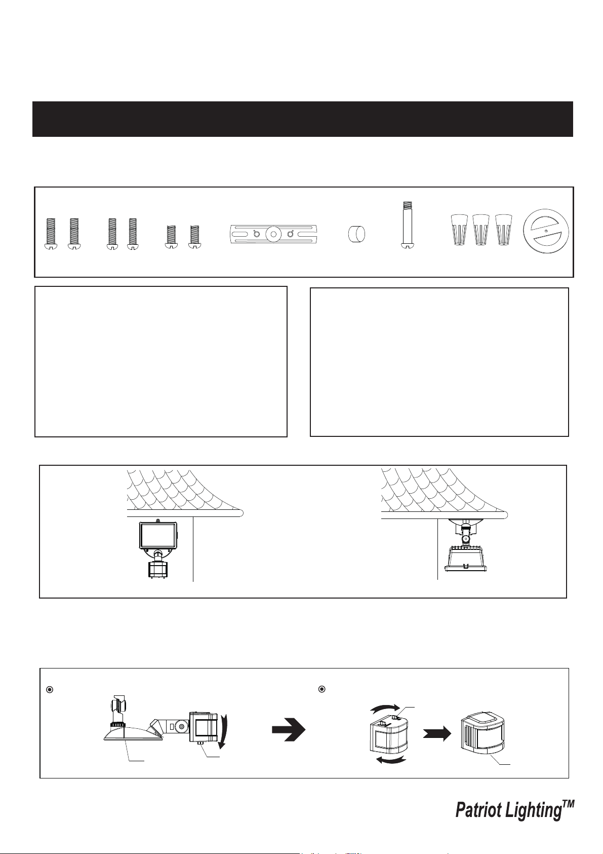
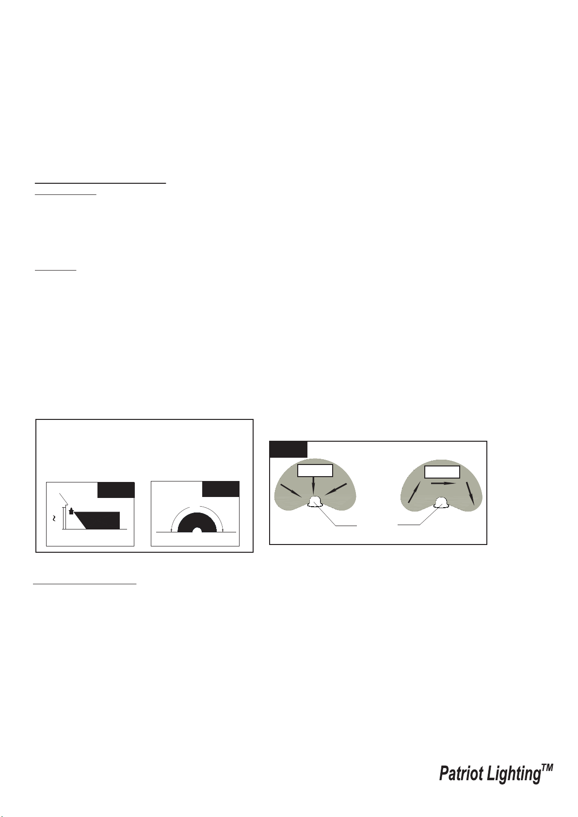
Note: Fixture can be wall mounted or eave mounted.
Wall Mounted
Eave Mounted
Read notes section on page 4 for additional information about mounting location of fixture.
Light fixture and sensor should be mounted as shown above when installed (depending upon type of installation)
Before installing the light fixture under an eave, the sensor head must be rotated as shown in the next two steps for
proper operation and to avoid the risk of electrical shock.
For eave mounted only:
Rotate the sensor head towards the back plate.
Rotate the sensor head clockwise 180˚ so the controls face down.
Controls
Back Plate
Controls
Controls
1. Motion sensor: turns light ON automatically when
motion is detected and turns light OFF automatically
when motion stops.
2. Photocell keeps the light OFF during daylight hours.
Hardware Package (included):
Decorative cover
Fixture Mounting Screw
Mounting Strap
Wire Nut X3
Gasket
Mounting Screw X2
#8/32X1/2 in
Mounting Screw X2
#6/32 X1/2 in
Mounting Screw X2
#10/24 X1/4 in

Installation Steps
Replacing Bulb Steps
Use a clean glove or cloth when handing the new blub. Use
isopropyl (rubbing) alcholol to clean the bulb if it is touched with
bare hands.
1. Using a phillips screwdriver (not included), loose the glass cover
locking screw on the light head and lower the glass cover.
2. To remove the bulb, push the bulb to the right until the left side
of the bulb is clear of the left bulb socket.
3. Place one end of the bulb on the contact in the right bulb socket.
While pushing the bulb agaist the contact, lower the other end of
the bulb onto the contact in the left bulb socket. The bulb should
spin easily if it is seated properly.
4.Before closing the glass cover, make sure the gasket is seated
properly in the groove around the edge of the light head. Close
the glass cover and tighten the locking screw securely.
Page 2 / 5
150619
Turn off the power at fuse or circuit box.
Turn on the power at fuse or circuit box.
Bulb
Gasket
Left Bulb
Socket
Right Bulb
Socket
Locking Screw
Glass
Cover
Light Head
Fig. 1
1. Install the mounting strap to the outlet box with the stamped word “FRONT” facing away from the outlet box, using
two mounting screws that best fit the outlet box. back plate should sit flush against wall surface when secured.
(Choose one matching pair of suitable mounting screws from the 3 pairs provided)
2. Fixture wires thread through gasket, then attach the gasket into back plate.
3. Pull out the source wires from the outlet box. Make wire connections using wire nuts as follows:
---Connect the black wire from the fixture to the “hot” wire from the power source. (usually black)
---Connect the white wire from the fixture to the neutral wire from the power source. (usually white)
---Connect the grounding wire from the fixture to the grounding wire from the power source. (usually green / yellow
insulation)
Carefully tuck the wires back into the outlet box.
4. Attach the back plate of the light fixture to the mounting strap, secure it with the fixture mounting screw.
5. Push the decorative cover firmly into the fixture mounting screw hole on the light.
6. With silicone caulking compound, caulk completely around where the back plate meets the wall surface.
CAUTION: Be sure to caulk completely where the back plate meets the wall surface to prevent water from
seeping into the outlet box.
Sensor
Mounting Strap
Outlet Box
Wire Nut
Back Plate
Mounting Screw
Fixture Mounting Screw
FRONT
Decorative cover
Gasket
T3 Halogen Bulb Max.150W
(included)
Light Head
Page 3 / 5
150619
Sensor Adjustment Lower For Short Coverage
Sensor Adjustment Higher For Long Coverage
Fig. 6
Fig. 5
Fig. 3
Fig. 4
Adjusting the Light Head:
1. Gently grasp the light heads and tilt them left or right, up or down by loosing the set screw in joint arm of sensor to
adjust the light coverage area. Keep the light heads at least 1” (25mm) away from the sensor. (See Fig. 6)
2. Keep the light heads 30˚ below horizontal to avoid water damage and electrical shock.
Sensitivity of Motion Sensor
● You can adjust the sensitivity of the motion sensor by using the “SENSITIVITY” selector located on the right
side of the bottom surface of the sensor. (See Fig. 5)
● Adjust motion sensor sensitivity to achieve desired performance.
● Approximate range for each setting from 10ft to 70ft.
Function and Operation
Choose a mode by rotating the switch on the bottom of the sensor of the fixture. (See Fig.5 )
Note: When power is first applied, the light will turn on immediately. Wait for 30 seconds to allow the sensor
to warm up.
1. TEST MODE (daytime and nighttime operation.)
● The light turns on automatically when motion is detected, and stays on as long as motion continues. About 5
seconds after motion is no longer detected, it turns off automatically.
sensor
Adjusting the Sensor Head:
1. Aim sensor head toward desired detection area, maintaining a
5° - 40° downward angle to allow moisture to drain.
Note: Make sure sensor head is positioned with controls facing
toward the ground.
2. You can move the sensor head up and down to change the coverage
area. (See Fig. 2)
Note: Range set too high may increase false triggering.
(See Fig. 3 and Fig. 4 )
Fig. 2
Set Screw
Page 4 / 5
150619
Customization Options:
Shut-off Delay
● The shut-off delay is the length of time the light will stay at brightness after motion is detected.
● You can set the shut-off delay by rotating the Time knob arrow so it points to the desired time setting (from 5
seconds to 3 minutes). To increase the shut-off delay, turn the knob clockwise. To decrease the shut-off delay,
turn the knob counterclockwise.
2. AUTO MODE (nighttime operation only)
● To shift to the “AUTO” mode, rotate knob arrow to the desired time setting (between 5 seconds and 3 minutes).
At dusk, the light turns on when motion is detected, and stays on as long as motion continues. When the motion
is no longer detected, the light remains on for the predetermined time you set (5s ~ 3min), and then turns off
automatically.
● The light turns off automatically at dawn.
Note: To make sure the above functions operate properly, always keep the wall switch in the “ON” position
(including the daytime).
Motion
Least sensitive
Motion
Most sensitive
Sensor
10'
8.0'
12.0'
70'
Where you install your fixture is important:
Be sure the light is mounted straight on the wall
or eave; otherwise, the detection distance may
be limited.
Fig. 7
Fig. 8
Fig. 9
Troubleshooting
---The light does not come on at all:
1. Make sure the wall switch and circuit breaker are on.
2. Make sure the wiring is correct.
3. Cover the sensor with dark color cloth to verify that the ambient light level is not too high.
---The light comes on for no apparent reason:
1. Re-aim the motion sensor.
2. Decrease the sensitivity setting.
3. Do not use a dimmer or timer to control the light fixture. Replace the dimmer or timer with a standard on/off wall
switch.
---The light flashes on and off:
1. Reposition the bulb away from the motion sensor.
2. Reposition the motion sensor.
3. The motion sensor is in “TEST” mode and warm up.
180˚
Notes:
1. The sensitivity of the motion sensor will increase as the environmental temperature gets cooler. For best
performance, gently clean the lens with a soft cloth every 1 or 2 months to ensure maximum sensitivity.
2. For best performance, install fixture at least 8 feet above the ground. At such a height, the fixture will provide a
detection distance of up to 70 feet at 77 degrees Fahrenheit. (See Fig.7)
3. The sensor detects movement across a detection range of 180 degrees. (See Fig.8)
4. The sensor will be more sensitive to motion across its detection path than motion directly towards it. (See Fig.9)
5. To reduce possible nuisances, do not mount the fixture near a heat source like an air conditioner, vent or furnace
exhaust, or in a direction facing any reflective object or other nearby light source.

Page 5 / 5
150619
5-YEAR LIMITED WARRANTY:
This Patriot Lighting fixture carries a limited warranty against defects in material or workmanship. If the Patriot Lighting
product fails at any time within five (5) years after the original date of sale due to defects in material or workmanship,
return the product to Menards with the original sales receipt. At its discretion, Patriot Lighting will replace the defective
fixture with the same or similar fixture or issue a refund. This warranty and any implied warranty (including but not limited
to any implied warranty of merchantability or fitness for a particular purpose) does not cover glass globes, light bulbs and
other expendable items. This warranty excludes coverage of finish or color against tarnishing, flaking, and discoloration.
If the original purchaser ceases to own the Patriot Lighting product this warranty and any implied warranty will be void.
This warranty does not cover damage caused by misuse or abuse, including but not limited to improper installation,
improper usage, accident, negligence, unauthorized repair, unauthorized modifications, or unauthorized maintenance of
the fixture. This warranty does not include reimbursement for inconvenience, installation, setup time, returned shipping
charges or defects, losses, labor, injuries to personal property.
This warranty gives the consumer specific legal rights, and the consumer may have other rights which vary from state to
state. The seller’s employees are not qualified to advise on the use of the fixture. Any oral representations made will
not be binding on seller or its employees.
For questions regarding this product, call us toll-free at 1-800-887-6326.
Assembly Kit
5353MM (1 SET)
The following parts are available for re-order if damaged or missing. Call us toll-free at 1-800-887-6326
Decorative cover
Fixture Mounting Screw
Mounting Strap
Wire Nut X3
Gasket
T3 Halogen Bulb Max.150W
8068HH(1PC)
Mounting Screw X2
#8/32X1/2 in
Mounting Screw X2
#6/32 X1/2 in
Mounting Screw X2
#10/24 X1/4 in