SKU Number: 343-2420
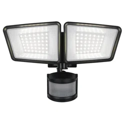
Linkable Solar Powered LED Security Wall Light
Model Number: ES01011G
Questions, problems, missing parts?
Before returning to your retailer, call our customer service at 855-232-6423
Monday – Friday 8:00 a.m. – 8:00 p.m. (EST)
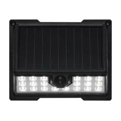
Solar Wall Light x 1
A B C
Plastic Anchor x 2 Mounting Screw x 2
PACKAGE CONTENTS
Read all instructions before installation, then store in a safe place for future reference. Failure to do so may result
in faulty assembly and potential injury.
SAFETY INFORMATION
• Your solar wall light is not a toy. Keep it out of reach from small children.
• Your solar wall light must be installed outdoors. Direct sunlight is needed for light to operate properly.
• If using a step ladder, you may require a second person to help install the solar wall light.
• Prior to installation, lay out all components and check against the part list section in this manual.
• CAUTION! Never look directly into the solar wall light when illuminated.
CLEANING AND MAINTENANCE
• The solar panel should be cleaned with a damp cotton cloth on a regular basis. This will ensure optimal performance and battery charging.
Periodically, utilize the same technique to clean the lenses of the motion sensor.
• Never let any abrasive material come into contact with the solar panel.
• To prolong the original appearance, clean the light fixture with a soft, damp cloth.
Do not use paints, solvents, or other chemicals on this light fixture.
LOCATION: Fixture can be wall mounted.
Some environmental factors may affect the sensor range and could result in a reduction in sensor detection distance.
It is recommended not to mount the fixture near a heat source like an air conditioner, vent, or furnace exhaust, or in a direction facing a light
reflecting object.
FEATURES:
Motion sensor: At night, turns light ON at automatically energy saving mode (low level brightness). When motion is detected, light illuminates at full
brightness for approximately 20 seconds. When movement detection ceases, the light will revert to energy saving mode after no motion is detected
for the set amount of time at night.
The light will turn off while the dawn is reached.
Sensor Range: Up to 8 m / 26 ft. x 120 degree spread (Varies with various environment).
Lumens output: 800 lumens / 5,000K (Max, after full charging).
Linkable distance up to 50ft at open space.
PREPARATION: Tools required for assembly (not included): Phillips screwdriver, safety goggles, power drill and ladder.
1
A
C
3.54i
nch/
9
c
m
C
B
B
C
B
A
5.
78 in
/
14.
7
c
m
INSTALLATION AND OPERATION INSTRUCTIONS
INSTALLATION
• Gently remove all parts from the package and lay them out on a smooth surface.
IMPORTANT: Ensure your solar panel is placed where it is exposed to optimized sunlight. Be aware of objects such as trees or property overhangs
that may impede the panel’s ability to generate a charge.
If install more than 1 light and you would like to have linkable function, you must link your lights first before installation begins.
You may link up to 20 lights. After the lights are linked you may begin the installation process.
LINKABLE SET-UP INSTRUCTION (THIS FUNCTION WORKS WITH MORE THAN 2 LIGHTS)
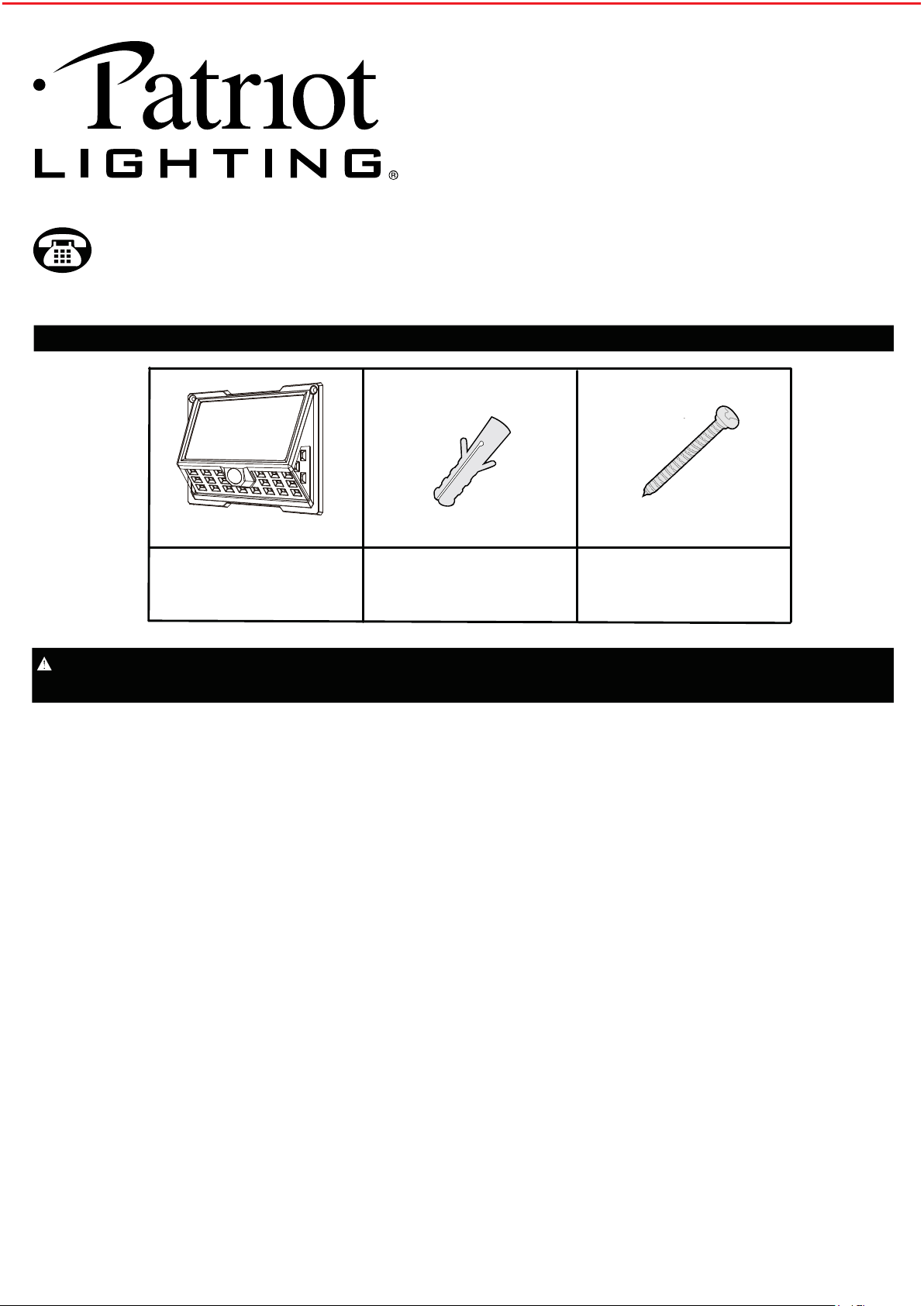
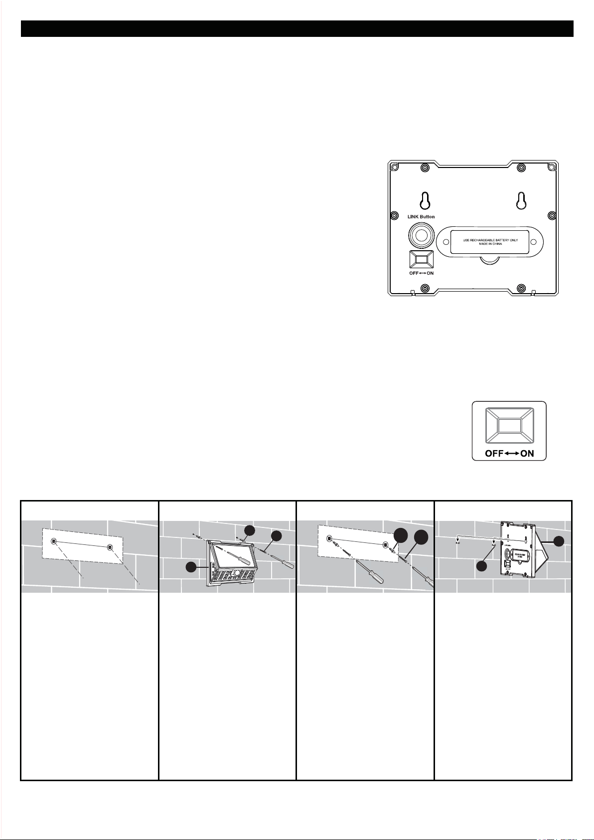
1. The "OFF-ON" switch and the “LINK Button" switch are all located on the back of the light.
Make sure every single light is switched to the "ON" position. Warm up time is approx. 15 seconds.
2. Select one light as the primary light, while the other light(or lights) will be the secondary light.
3. Signal Matching.
A - After 15 seconds "warm-up" period, press and hold the “LINK Button” switch on the
primary light for 3 - 5 seconds. The light will then flash slowly (1 time per second).
B - Press the “LINK Button” switch once on the secondary light.
When the secondary light flashes quickly (2 times per second) then turns off,
it means they are linked together successfully.
C - Repeat step B until all secondary lights are linked. When all lights are successfully
connected, press the primary light’s “LINK Button” switch once to cease linking.
D - When linked, all lights will illuminate to full brightness when any single one of them
detects motion. After 20 seconds of no motion detection, the lights will return back
to the low-level dusk-to-dawn brightness.
E - To remove the linkable function, press the “LINK Button” switch twice on each light
you choose to disconnect. The light will illuminate for 2 seconds and then turn off.
TROUBLE SHOOTING ON FAIL LINKABLE CONNECTING
1. Please check all lights and make sure every light is switched to the “ON” position.
2. Check that the primary light is flashing slowly. If not, press the “Link Button” switch 3-5 seconds to make sure the light flashes slowly.
3. Check that the secondary light flashes quickly. If not, please power off then back on, and press the "Link Button" switch once again.
4. Check that the distance between the primary light & the secondary light is no more than 50-ft apart, and that there are no obstacles in
between.Connectivity can be up to 50-ft between each light.
Prior to using your solar wall light, initial charge is needed and it should be done in the OFF position for at least three sunny days. After the third
day, your included battery will be enough power for operation of solar wall light.
1. Place the first mounting
bracket template (refer to the
template shown on the last
page of this instruction) over
the desired mounting
surface.
Mark the screw hole
locations indicated by the X
symbol for the
solar wall light.
2. Use a power drill (not
included) to drill two 13/64
inch holes into the mounting
surface. Insert the plastic
archors (B) in the holes and
fasten the solar wall light (A)
onto the wall with attached
mounting screws(C).
3. Another install type:
Place the second mounting
bracket template (refer to the
template shown on the last
page of this instruction) over
the desired mounting
surface. Mark the screw hole
locations indicated by the X
symbol for the solar wall
light.
4. Drill two 13/64 inch holes
into the mounting surface.
Insert the plastic anchors (B)
into the holes. Screw the
mounting screws (C) into the
anchors (B), leaving about
1/4 inch of the screws (C)
sticking out of the mounting
surface. Align and place the
two mounting holes on the
back of the solar wall light (A)
over the mounting screws
(C).
2
INSTALL THE LIGHT ON THE WALL
Questions, problems, missing parts?
Before returning to your retailer, call our customer service at 855-232-6423
Monday – Friday 8:00 a.m. – 8:00 p.m. (EST)
BATTERY REPLACEMENT
FREQUENTLY ASKED QUESTIONS
OPERATIONAL INSTRUCTIONS
Please slide the OFF-ON switch to "ON" position and linked your lights (if needed) before install your lights as above.
While slide the OFF-ON switch to "ON" position the light will turn on and enter a "warm-up" period for about 15 seconds, the light illuminates
automatically at dusk using an energy saving mode of low brightness.
When motion is detected at night, the light illuminates at full brightness for approximately 20 seconds.
Fully charged use for this light is approximately 36 minutes calculated using 20 seconds per cycle.
The light will not turn on at daytime.
Q: Where should the solar panel be mounted?
A: Mount your solar panel in a position that will enable the most amount of light to be absorbed. In the Northern Hemisphere this is usually south
facing.
Q: Does the solar panel require direct sun to charge?
A: The solar panel can charge the internal battery in direct and indirect light. For best results, try to keep your solar panel’s sun exposure.
Q: Will decorative or street lights have an effect on the motion sensor's ability to operate?
A: Yes, the sensor of the solar wall light is light-sensitive. For nighttime usage, ensure no other light affects the motion sensor.
Q: What type of battery does my solar wall light require to operate?
A: Your solar wall light requires the use of 1 pc of 3.7V 18650 1,800 mAh Lithium ion rechargeable battery (18650 3.7V 2,000mAh Lithium ion
rechargeable battery can works in this unit too).
When replacing the batteries, be sure to:
• Use same specification rechargeable battery (1 pc 18650 3.7V 1,800mAh Lithium ion rechargeable battery,
18650 3.7V 2,000mAh Lithium ion rechargeable battery can works in this unit too).
• Observe the correct polarity (+ and -) when installing the replacement battery.
• IMPORTANT: Dispose of the Lithium ion battery in accordance with local,
state and federal regulations.
Battery is located in the battery housing behind the light fixture.
Slide the OFF-ON switch to OFF position on the light prior to opening the battery housing.
Remove the screws to reveal the battery.
When replacing the battery, observe the correct polarity and match the battery specification with the battery you have removed.
Use rechargeable battery only.
The first time use after new battery change. Slide the OFF-ON switch to ON position the light will turn on and enter a "warm-up"
period for about 15 seconds.
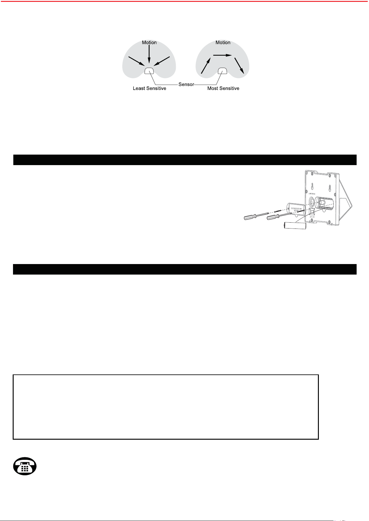
Recommended installation height: 4.5 ~ 8 feet above the ground.
At such a height, The fixture will provide a detection distance of up to 26 feet (Max) at ambient temperature of 77 degrees Fahrenheit.
The sensor will be more sensitive to motion across than motion towards it directly.
ONE-YEAR LIMITED WARRANTY:
If, during normal use, this PATRIOT LIGHTING
®
lighting fixture breaks or fails
due to a defect in material and workmanship within one (1) year from the date of original purchase,simply bring this
lighting fixture with the original sales receipt back to your nearest MENARDS
®
retail store. At its discretion, PATRIOT
LIGHTING
®
agrees to have the product or any defective part(s) repaired or replaced with the same or similar PATRIOT
LIGHTING
®
product or part free of charge, within the stated warranty period, when returmed by the original purchaser
with original sales receipt. This warranty; (1) excludes expendable parts including but not limited to light bulbs and
batteries; (2) does not cover damage that has resulted from abuse or misuse; and (3) does not cover any losses,
labor, injuries to persons/property or costs. This warranty does give you specific legal rights and you may have other
rights, which vary from state to state.
3
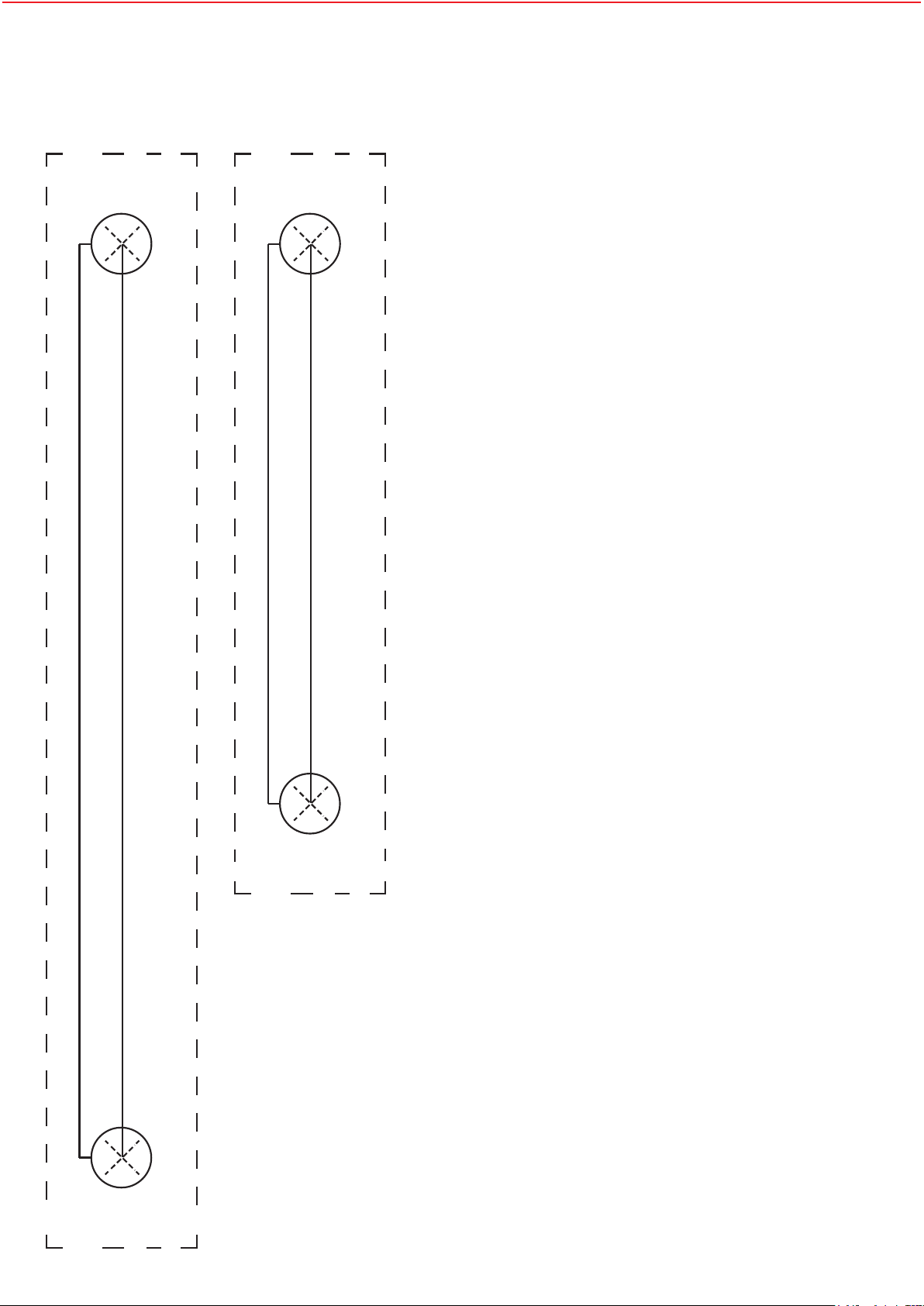
MOUNTING BRACKET TEMPLATE INSTRUCTIONS
1. Cut out the mounting bracket template.
2. Mark the screw hole locations(X) using a pencil or drill.
3. Drill holes in the marked locations.
4
5.78 in / 14.7 cm
3.54inch/ 9cm