PRIME MAGNETIC BELT DRIVE
INDOOR CYCLING BIKE
SF-B122061
USER MANUAL
IMPORTANT! Please retain owner’s manual for maintenance and adjustment instructions. Your
satisfaction is very important to us, PLEASE DO NOT RETURN UNTIL YOU HAVE CONTACTED
US: support@sunnyhealthfitness.com or 1-877-90SUNNY (877-907-8669).

1
IMPORTANT SAFETY INFORMATION
We thank you for choosing our product. To ensure your safety and health, please use this
equipment correctly. It is important to read this entire manual before assembling and using the
equipment. Safe and effective use can only be achieved if the equipment is assembled,
maintained, and used properly. It is your responsibility to ensure that all users of the equipment
are informed of all warnings and precautions.
1. Before starting any exercise program, you should consult your physician to determine if you
have any medical or physical conditions that could put your health and safety at risk or prevent
you from using the equipment properly. Your physician’s advice is essential if you are taking
medication that affects your heart rate, blood pressure, or cholesterol level.
2. Be aware of your body’s signals. Incorrect or excessive exercise can damage your health.
Stop exercising if you experience any of the following symptoms: pain, tightness in your chest,
irregular heartbeat, shortness of breath, lightheadedness, dizziness, or feelings of nausea. If
you do experience any of these conditions, you should consult your physician before
continuing with your exercise program.
3. Keep children and pets away from the equipment. The equipment is designed for adult use
only.
4. Use the equipment on a solid, flat level surface with a protective cover for your floor or carpet.
To ensure safety, the equipment should have at least 2 feet (60 CM) of free space all around it.
5. Ensure that all nuts and bolts are securely tightened before using the equipment. The safety of
the equipment can only be maintained if it is regularly examined for damage and/or wear and
tear.
6. Always use the equipment as indicated. If you find any defective components while
assembling or checking the equipment, or if you hear any unusual noises coming from the
equipment during exercise, discontinue use of the equipment immediately and do not use until
the problem has been rectified.
7. Wear suitable clothing while using the equipment. Avoid wearing loose clothing that may
become entangled in the equipment.
8. Do not place fingers or objects into the moving parts of the equipment.
9. The maximum weight capacity of this unit is 265 lbs (120 kgs).
10. This equipment is not suitable for therapeutic use.
11. To avoid bodily injury and/or damage to the product or property, proper lifting and moving are
required.
12. Your product is intended for use in cool and dry conditions. You should avoid storage in
extreme cold, hot or damp areas as this may lead to corrosion and other related problems.
13. This equipment is designed for indoor and home use only; it is not intended for commercial
use.
2
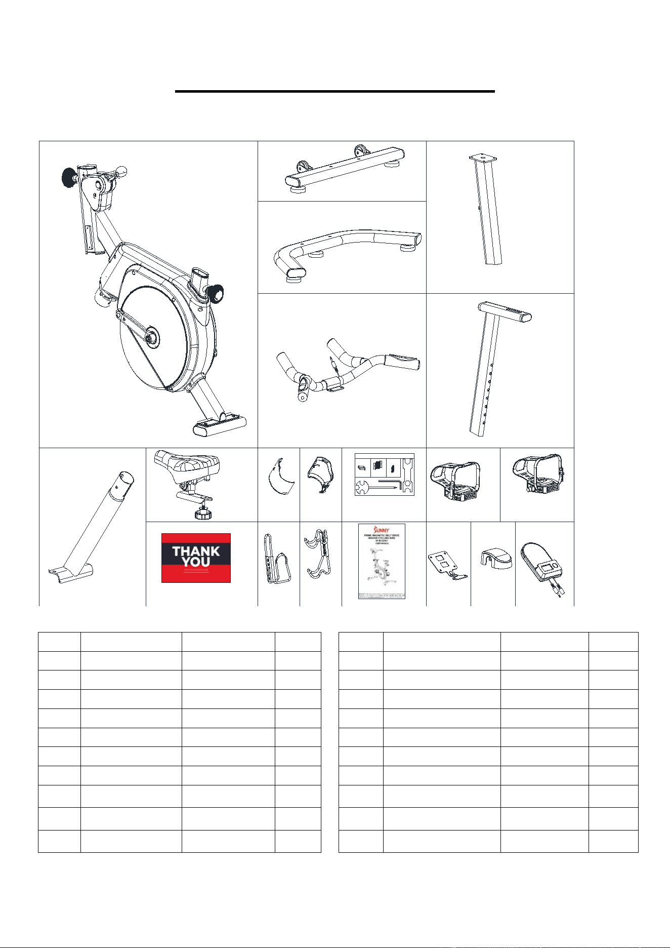
PRE-ASSEMBLY CHECK LIST
. Before you start to assemble, please make sure all parts are included.
1
4
5
3
2
7
15
31
101
102
106
107
D
E
87
8
53
10
86
#108 M5*6*φ10 4PCS
#39 M6*15*S5 4PCS
#40 d6 4PCS
STEP 7
STEP 4
HARDWARE PACKAGE SF-B122061
#41 d6*Φ16*1.5 4PCS
A S5 1PC
B S13-14-15 1PC
C S17-19 1PC
STEP 1
#29 ST4.2*19*φ8 2PCS
F
No. Description Spec. Qty. No. Description Spec. Qty.
1
Main Frame
1
53
Cover
113*76.5*44
1
2
Handlebar Post
1 86
Left Pedal
9/16, L 1
3
Handlebar
1 87
Right Pedal
9/16, R 1
4
Front Stabilizer
1 101
Cover L
93*89*44.5
1
5 Rear Stabilizer
1 102
Cover R
93*89*44.5
1
7 Seat Post
1 106
Bottle Holder
65*78*168
1
8
Mounting Plate
1 107
Dumbbell Rack
70*80*154
1
10 Computer
1 D Hardware package 1
15 Supporting Tube
1 E User Manual 1
31
Seat
1 F Thank You Card 1
3
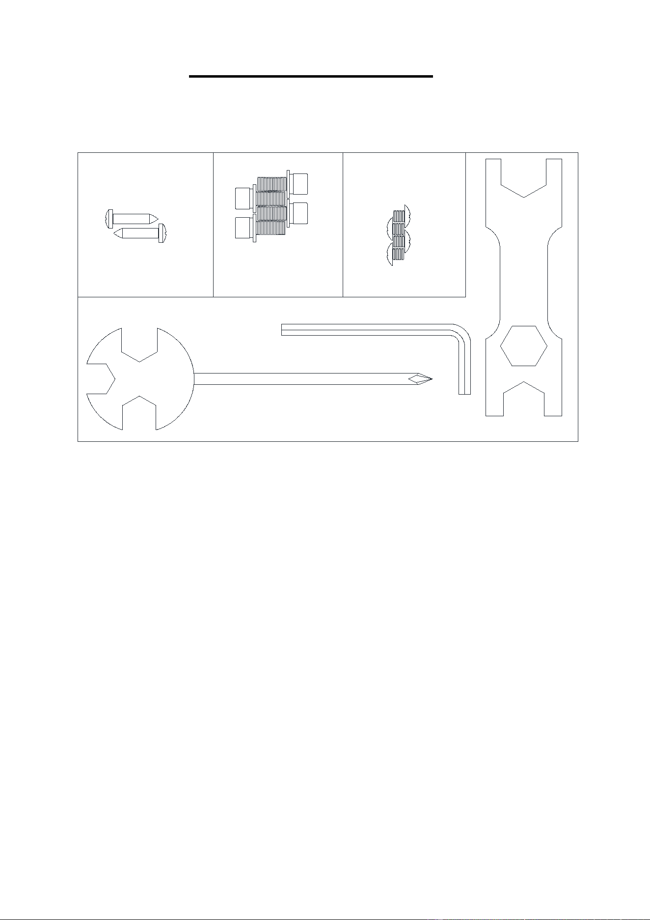
HARDWARE PACKAGE
HARDWARE PACKAGE SF-B122061
#108 M5*6*φ10 4PCS
#39 M6*15*S5 4PCS
#40 d6 4PCS
STEP 8
STEP 5
#41 d6*Φ16*1.5 4PCS
A S5 1PC
B S13-14-15 1PC
C S17-19 1PC
STEP 2
#29 ST4.2*19*φ8 2PCS
Ordering Replacement Parts (U.S. and Canadian Customers only)
Please provide the following information in order for us to accurately identify the part(s) needed:
The model number (found on cover of manual)
The product name (found on cover of manual)
The part number found on the “EXPLODED DIAGRAM” (page 16) and “PARTS LIST”
(pages 14-15).
Please contact us at support@sunnyhealthfitness.com or 1-877-90SUNNY (877-907-8669).
4
ASSEMBLY INSTRUCTIONS
We value your experience using Sunny Health and Fitness products. For assistance with parts
or troubleshooting, please contact us at support@sunnyhealthfitness.com or 1- 877 - 90SUNNY
(877-907-8669).
42 M8*20*S5 2PCS
43 d8 2PCS
44 d8*Φ16*1.5 2PCS
A S5 1PC
15
42
43
44
4
42 M8*20*S5 4PCS
43 d8 4PCS
91 d8*Φ20*1.5*R30 4PCS
A S5 1PC
29
101
42
43
91
42
43
91
102
29
1
15
29 ST4.2*19*Φ8 2PCS
B S13-14-15 1PC
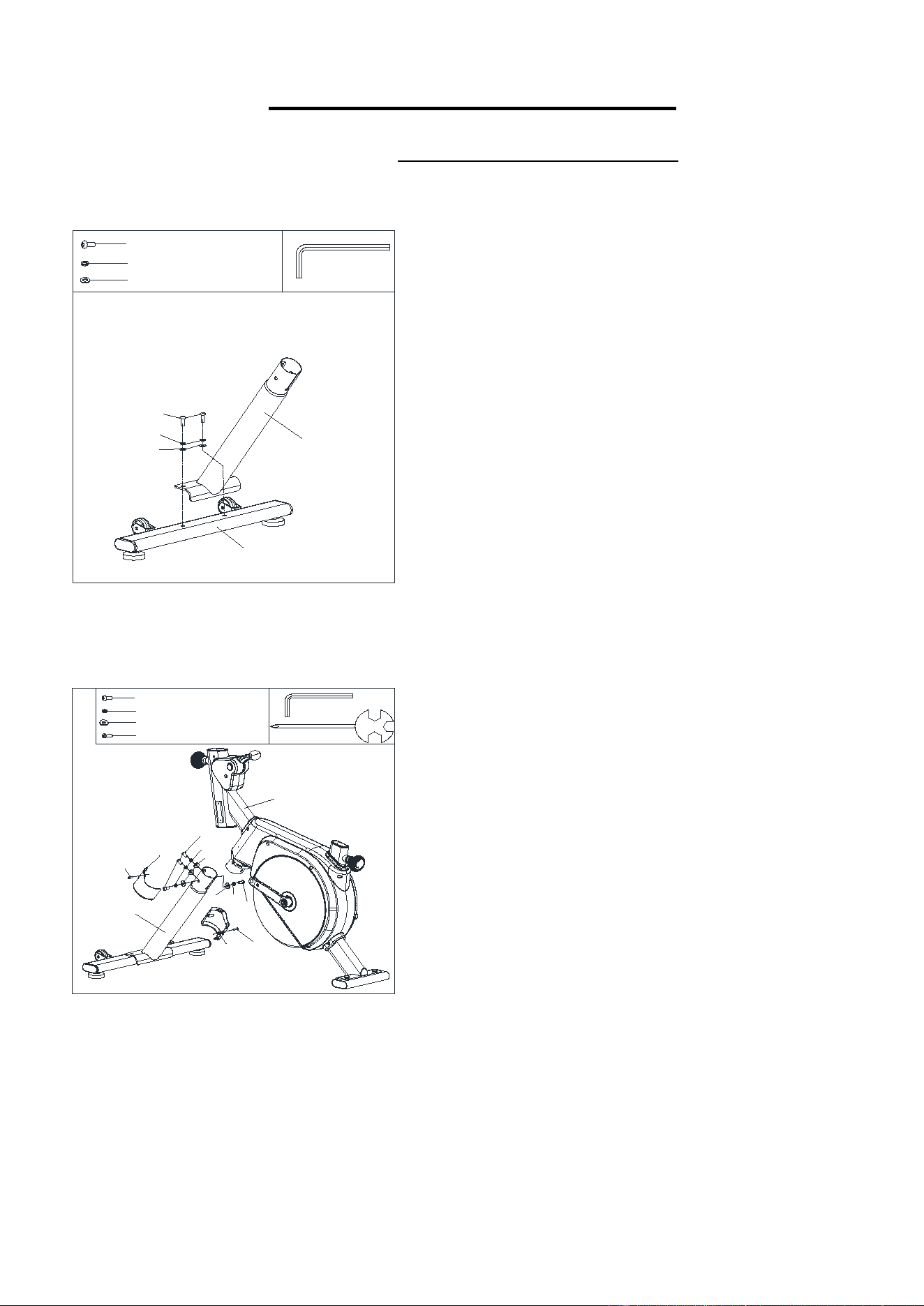
STEP 2:
Remove 4 Bolts (No. 42), 4 Spring Washers
(No. 43), and 4 Arc Washers (No. 91) from
Supporting Tube (No. 15) by Spanner (No. A).
Attach the Supporting Tube (No. 15) to the Main
Frame (No. 1) using 4 Bolts (No. 42), 4 Spring
Washers (No. 43), and 4 Arc Washers (No. 91)
that were just removed. Tighten with Spanner
(No. A).
Attach the Cover L (No. 101) and Cover R
(
No.
102) onto the Supporting Tube (No. 15) using 2
Screws (No. 29). Tighten with Spanner (No. B).
STEP 1:
Remove 2 Bolts (No. 42), 2 Spring Washers
(No. 43), and 2 Washers (No. 44) from Front
Stabilizer (No. 4) by Spanner (No. A).
Attach the Front Stabilizers (No. 4) to the
Supporting Tube (No. 15) by using 2 Bolts (No.
42), 2 Spring Washers (No. 43), and 2 Washers
(No. 44).
Tighten with
Spanner (No. A).
5
We value your experience using Sunny Health and Fitness products. For assistance with parts
or troubleshooting, please contact us at support@sunnyhealthfitness.com or 1-877-90SUNNY
(877-907-8669).
42
43
44
42
43
44
5
11
1
a
A S5 1PC
42 M8*20*S5 2PCS
43 d8 2PCS
44 d8*Φ16*1.5 2PCS
B S13-14-15 1PC
S15
C S17-19 1PC
B
S15
86
83
88
86
83
C
S19
87
84
B
S15
87
84
89
C
S19
B
S15
B
S15
86
87
88
89
83
84
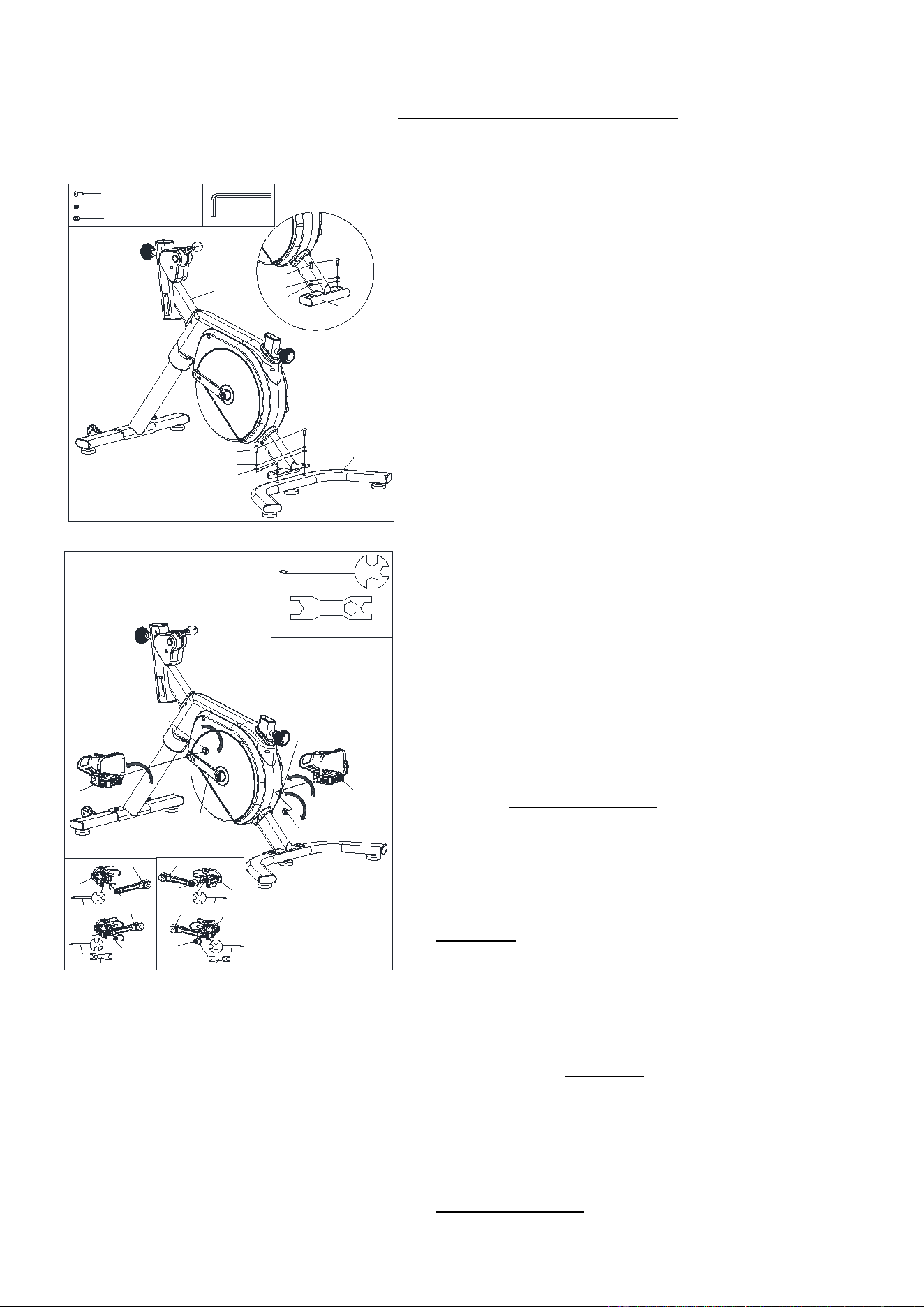
STEP 3:
Remove 2 Bolts (No. 42), 2 Spring Washers
(No. 43), and 2 Washers (No. 44) from Main
Frame (No. 1) by Spanner (No. A). Discard
Packaging Tube (No. 11) which is not needed
for the assembly (Figure A).
Attach the Rear Stabilizers (No. 5) to the Main
Frame (No. 1) by using 2 Bolts (No. 42), 2
Spring Washers (No. 43), and 2 Washers (No.
44). Tighten with
Spanner (No. A).
STEP 4:
NOTE: Left Pedal (No. 86) is marked "L" and
Right Pedal (No. 87) is marked “R”.
Screw out the Left & Right Nylon Nuts (No. 88 &
No. 89) from Left & Right Pedals (No. 86 & No.
87) by Spanner (No. C).
Align the Left Pedal (No. 86) with the Left Crank
(No. 83) at 90° and gently insert the Left Pedal
(No. 86) into the crank arm. Turn the Left Pedal
(No. 86) counter-clockwise as tightly as you can
with your hand, then tighten and securely with
Spanner (No. B).
Hold the bolt of Left Pedal (No. 86) by Spanner
(No. B). Screw the Left Nylon Nut (No. 88)
clockwise to the thread end of the Left Pedal (No.
86) securely with Spanner (No. C).
Align the Right Pedal (No. 87) with the Right
Crank (No. 84) at 90° and gently insert the Right
Pedal (No. 87) into the crank arm. Turn the Right
Pedal (No. 87) clockwise as tightly as you can with
your hand, then tighten and securely with Spanner
(No. B).
Hold the bolt of Right Pedal (No. 87) by Spanner
(No. B). Screw the Right Nylon Nut (No. 89)
counter-clockwise to the thread end of the Right
Pedal (No. 87) securely with Spanner (No. C).
6
We value your experience using Sunny Health and Fitness products. For assistance with parts
or troubleshooting, please contact us at support@sunnyhealthfitness.com or 1-877-90SUNNY
(877-907-8669).
39 M6*15*S5 4PCS
40 d6 4PCS
41 d6*Φ16*1.5 4PCS
A S5 1PC
30
18
2
19
8
53
3
39
40
41
39
40
41
1
18
19
a
B S13-14-15 1PC
10
105
19
16
10b
10a
8
10b
10a
19
16
a
10
10b
10a
b
8
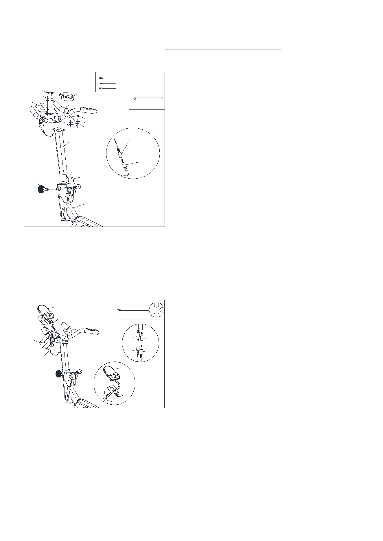
STEP 5:
Connect Sensor Wire (No. 18) with Trunk Wire
(No. 19). (Figure A).
Loosen and pull out the Knob (No. 30) from
Main Frame (No. 1).
Then insert the Handlebar Post (No. 2) to Main
Frame (No. 1), insert and tighten with the Knob
(No. 30) after adjusting the Handlebar Post (No.
2) to the desired position.
Attach the Handlebar (No. 3) on the Handlebar
Post (No. 2) using 2 Bolts (No. 39), 2 Spring
Washers (No. 40) and 2 Washers (No. 41).
Attach the Mounting Plate (No. 8) in front of the
Handlebar (No. 3) using 2 Bolts (No. 39), 2
Spring Washers (No. 40) and 2 Washers (No.
41). Tighten with Spanner (No. A), then put on the
Cover (No. 53).
STEP 6:
Remove the 4 Screws (No. 105) from the back of
Computer (No. 10) by Spanner (No. B).
First, put Computer Wire 1 (No. 10a) and
Computer Wire 2 (No. 10b) through the hole of
Mounting Plate (No. 8) (Figure b).
Attach the Computer (No. 10) to the Mounting
Plate (No. 8) using the 4 Screws (No. 105) by
Spanner (No. B).
Connect Computer Wire 1 (No. 10a) with Trunk
Wire (No. 19), connect Computer Wire 2 (No.
10b) with Pulse Sensor Wire (No. 16) (Figure a).
7
We value your experience using Sunny Health and Fitness products. For assistance with parts
or troubleshooting, please contact us at support@sunnyhealthfitness.com or 1-877-90SUNNY
(877-907-8669).
33 d10*Φ30*2.5 1PC
32 M10*Φ58*32 1PC
30
7
9
32
33
1
B S13-14-15 1PC
108 M5*6*φ10 4PCS
1
106
107
108
108
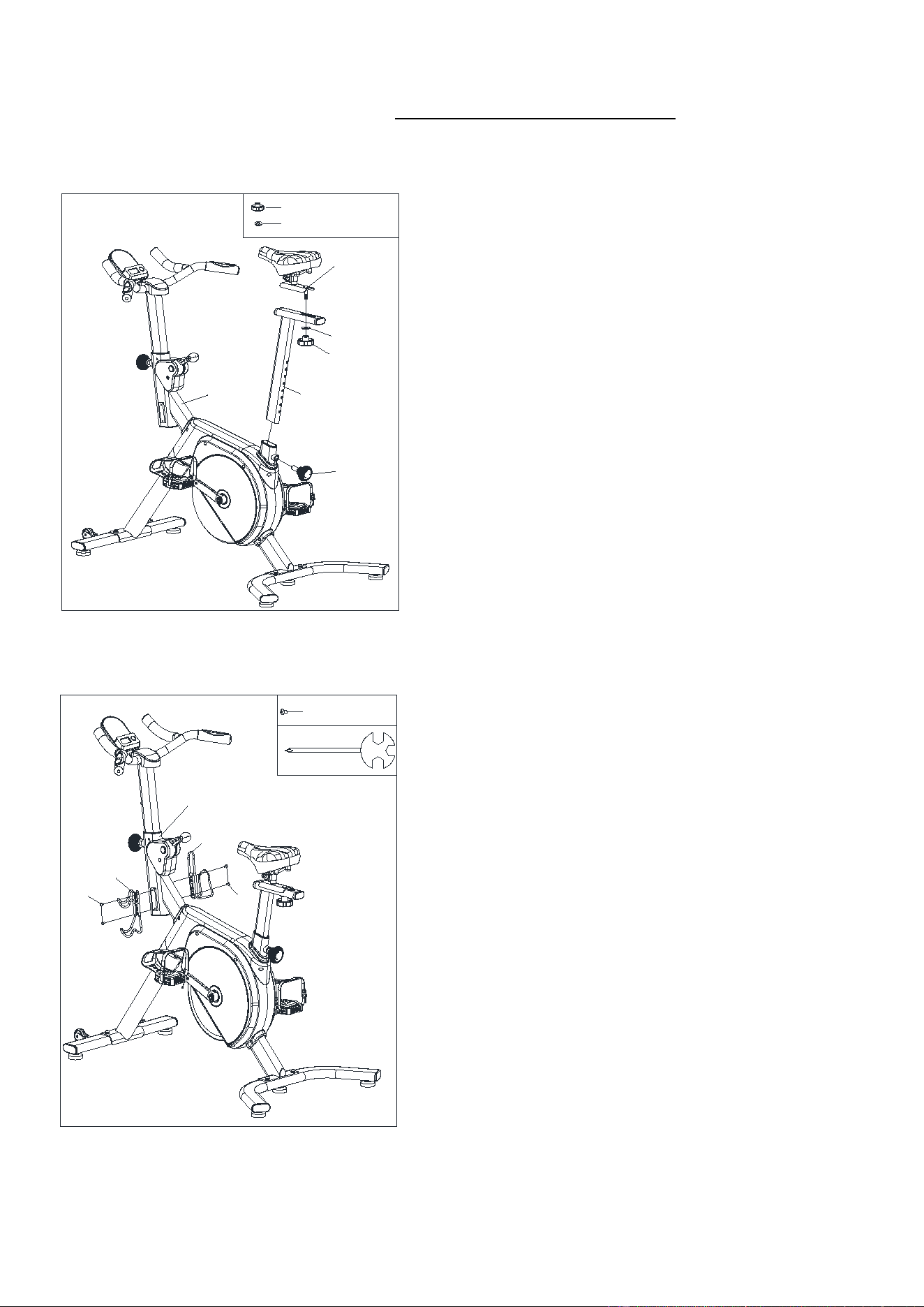
STEP 7:
Loosen and pull out the Knob (No. 30) from
Main Frame (No. 1).
Then insert the Seat Post (No. 7) to Main Frame
(No. 1), insert and tighten with the Knob (No. 30)
after adjusting the Seat Post (No. 7) to the desired
position.
Remove the Washer (No. 33) and the Knob (No.
32) from the Seat Slider (No. 9).
Attach the Seat Slider (No. 9) on the Seat Post
(No. 7), tighten and secure with Washer (No.33)
and Knob (No. 32) after adjusting to the desired
position.
STEP 8:
Attach Bottle Holder (No. 106) on the right of
Main Frame (No. 1) with 2 Screws (No. 108).
Tighten with Spanner (No. B).
Attach Dumbbell Rack (No. 107) on the left of
Main Frame (No. 1) with 2 Screws (No. 108).
Tighten with Spanner (No. B).
The assembly is complete!
8
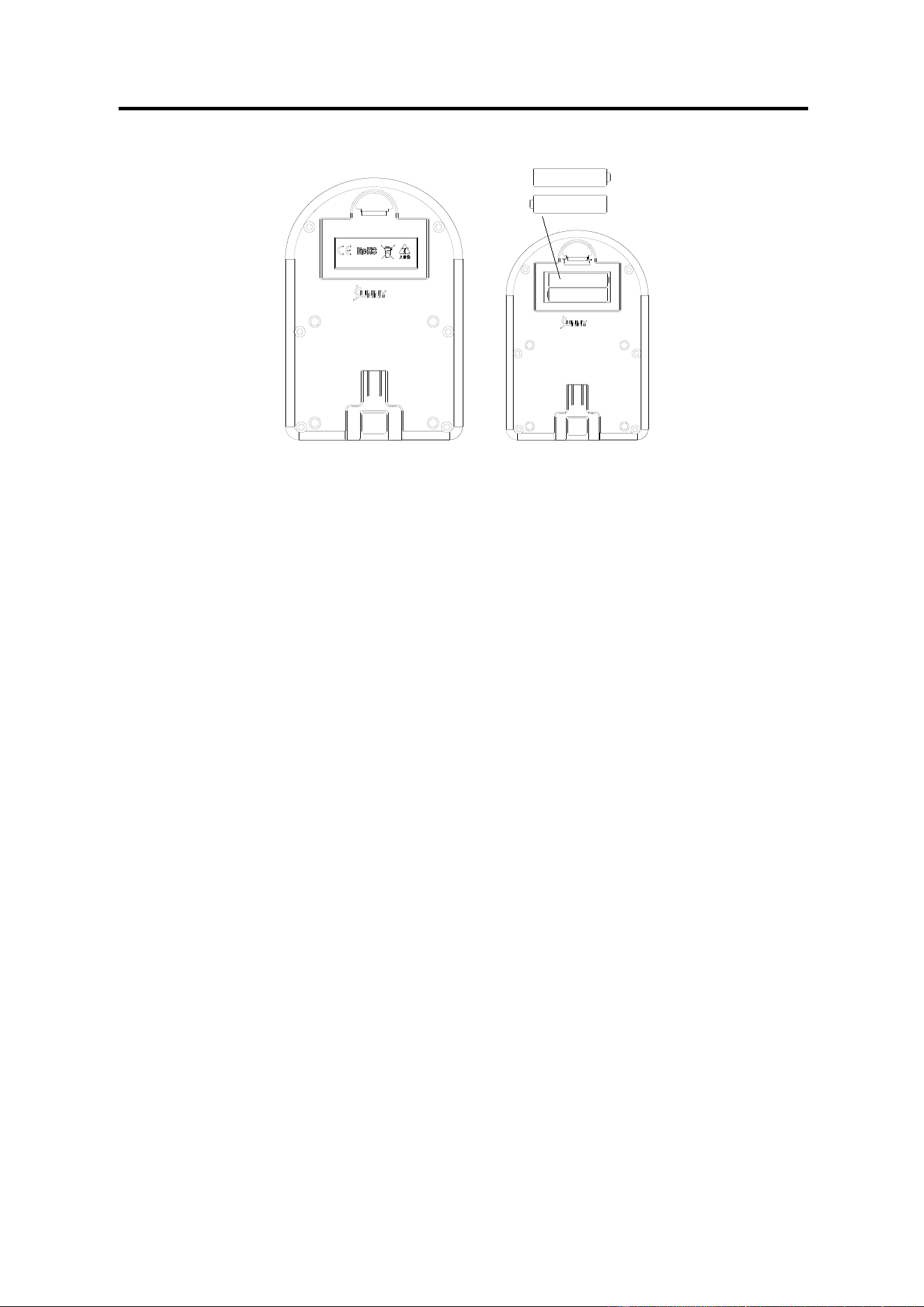
BATTERY INSTALLATION AND REPLACEMENT
BATTERY INSTALLATION
1. Take out 2 AAA batteries from computer box.
2. Press the buckle of battery cover on the back of the Computer (No. 10), then remove battery
cover.
3. Install 2 AAA batteries into the battery case on the back of the Computer (No. 10). Pay attention
to the battery + and – poles before installing.
4. Press the buckle of battery cover, then put the battery cover back to the back of the Computer
(No. 10).
The installation is complete!
BATTERY REPLACEMENT
1. Press the buckle of battery cover on the back of the Computer (No. 10), then remove battery
cover.
2. Remove the 2 old AAA batteries in the battery case and install 2 new AAA batteries into the
battery case on the back of the Computer (No. 10). Pay attention to the battery + and – poles
before installing.
3. Press the buckle of battery cover, then put the battery cover back to the back of the Computer
(No. 10).
The replacement is complete!
NOTE: Always change both batteries at the same time. Do not mix battery types and do not mix old
and new batteries. Dispose batteries according to your state and regional guidelines.
9
ADJUSTMENTS & USAGE GUIDE
A
B
20
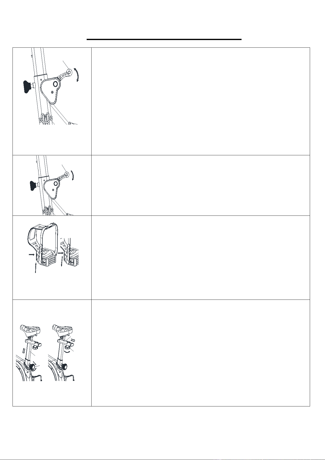
TENSION ADJUSTMENT:
Increasing or decreasing the resistance allows you to add variety to
your workout sessions.
There are 7 levels resistance. Level 1 is the lowest and level 7 is the
highest.
To increase the resistance, pull the Tension and Brake Handle (No.
20) (“+”) down (Arrow B). When you hear a "click", it means the
resistance is increased by 1 level.
To decrease the resistance, push the Tension and Brake Handle (No.
20) (“-”) up (Arrow A). When you hear a "click", it means the resistance is
decreased by 1 level.
20
EMERGENCY BRAKE FUNCTION:
The flywheel of the bike has a large inertia. When you need to get off the
bike, pull down the Tension and Brake Handle (No. 20) firmly. Please
wait until the flywheel has completely stopped rotating before releasing
the Tension and Brake Handle (No. 20). You can get off the bike once
the flywheel has stopped.
A
B
PEDAL STRAP ADJUSTMENT:
1. When you feel the pedal is too tight, press the buckle and pull the
strap upward to loosen the strap (see Figure A);
2. When you feel that the
pedal is too loose, press the buckle and pull the
strap down to tighten the strap (see Figure B).
3. This product is recommended to step in the forward direction, and the
backward direction is easy to cause loose pedal with gaps or abnormal
sounds. If it is really loose, it should be locked with a Spanner in time.
9
B
7
32
30
A
SEAT ADJUSTMENT:
The seat of this bike is fully adjustable. Move Seat Post (No. 7) up and
down: Loosen and pull out the Knob (No. 30), then raise or lower the
Seat Post (No. 7) to the desired height. Once adjusted, re-insert and
tighten the Knob (No. 30) to secure the Seat Post (No. 7) in place.
(Figure A).
Move Seat Slider (No. 9) forward and backward: Loosen the Knob
(No. 32), then move the Seat Slider (No. 9) forward or backward to
the desired position, then tighten the Knob (No. 32). (Figure B).
10
30
2
3
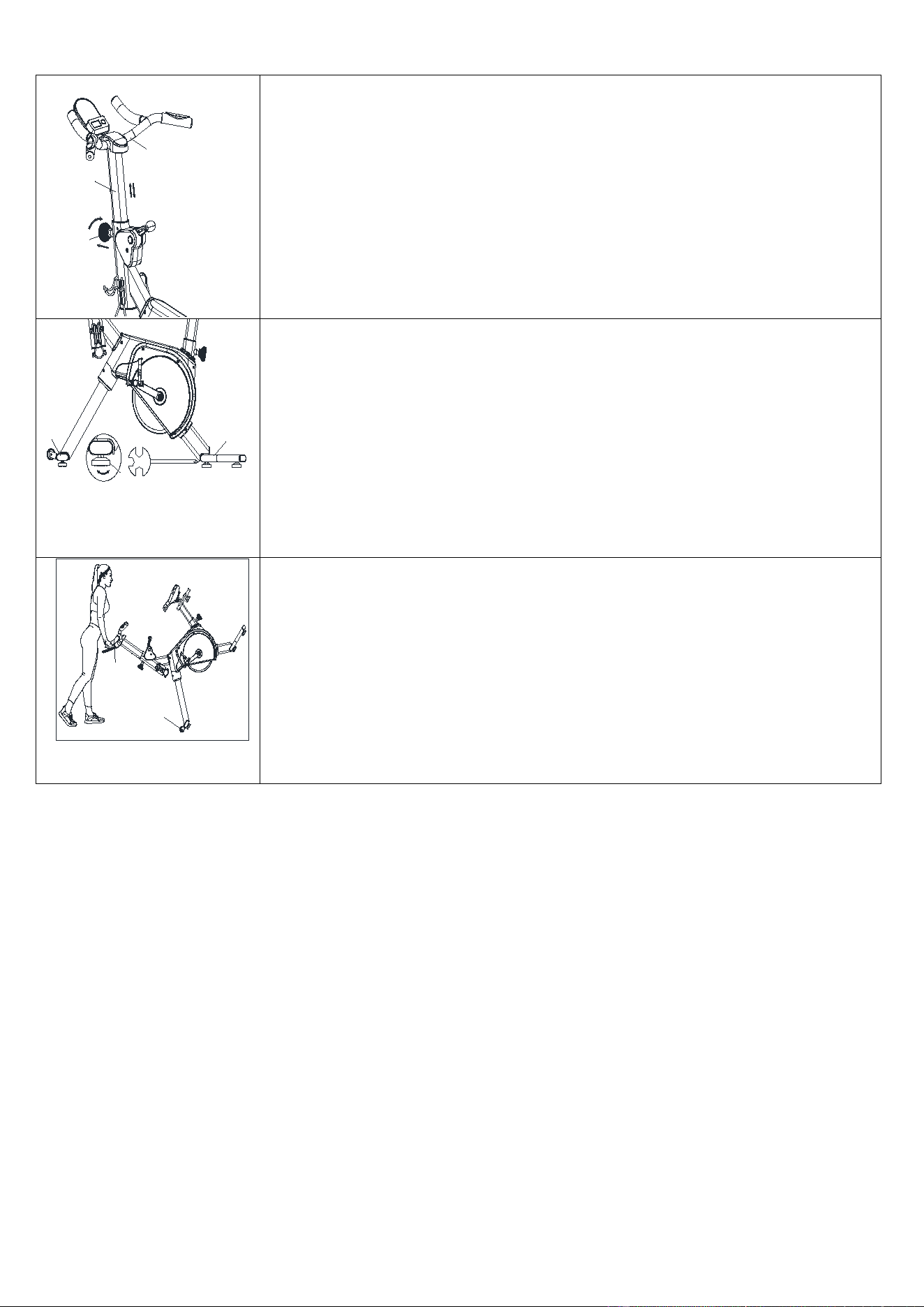
HANDLEBAR ADJUSTMENT:
To adjust the height of Handlebar (No. 3), loosen and pull out the Knob
(No. 30), then slide the Handlebar Post (No. 2) up or down to the
desired height. Once adjusted, re-insert and tighten the Knob (No. 30) to
secure the Handlebar Post (No. 2) in place.
49
B S13-14-15 1PC
4
5
A
B
BALANCE ADJUSTMENT:
During use, if you notice that the bike is unbalanced, you can adjust
the Foot Pad (No. 49) located beneath the Front & Rear Stabilizers
(No. 4 & No. 5). Rotate the Foot Pad (No. 49) to direction A or B until
the bike is balance, then use Spanner (No. B) to re-tighten.
46
3
MOVE THE BIKE:
To move the bike, stand at the front of the bike, firmly grasp and hold
each side of the Handlebar (No. 3), place one foot on the Front
Stabilizer (No. 4) and tilt the bike towards you until the Transport Wheel
(No. 46) touch the ground. With the Transport Wheels (No. 46) on the
ground, you can transport the bike to the desired location with ease.
11
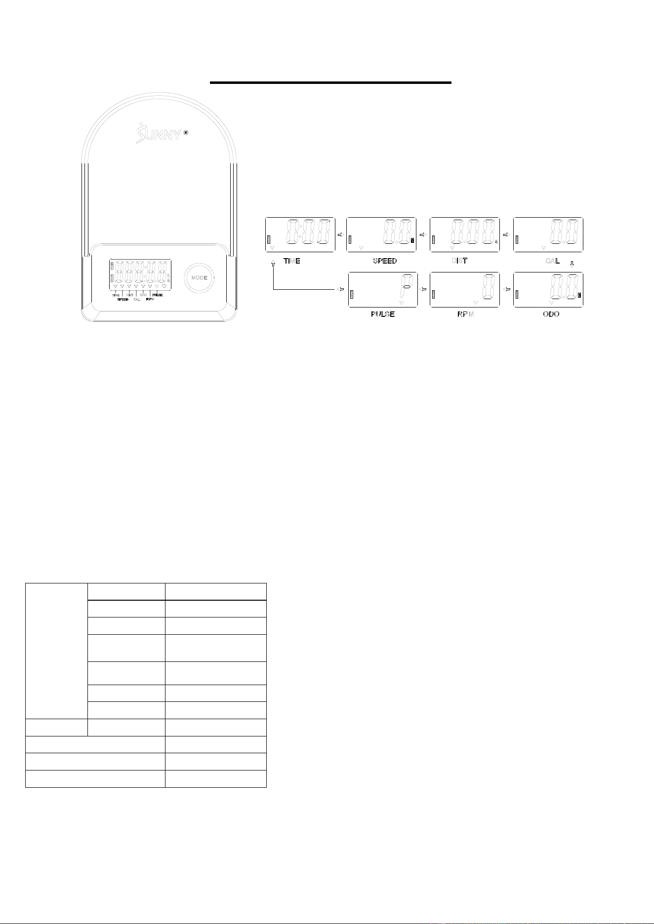
EXERCISE COMPUTER
■KEY FUNCTIONS
:
Pressing the MODE key to select and lock on a function for following sequence: SCANTIME SPEED DIST (DIATANCE) CAL
(CALORIES) ODO (TOTAL DISTANCE) RPMPULSE SCAN
Pressing and hold the MODE key with 3 seconds to reset the value to zero (without ODO).
■SLEEP MODE:
The system turns on when the MODE key is pressed or system sensed a signal input from the sensor.
The system turns off automatically when the sensor has no signal input or no key are pressed for approximately 4 minutes.
■FUNCTIONS:
SCAN: Display changes according to the next diagram every 6 seconds.
SPEED: The current speed with starting exercise.
DIST: The current distance with starting exercise.
TIME: The working times with starting exercise.
ODO: The total distance which refers to the distance with the battery’s life from the beginning to the end.
CAL: The calories burned with starting exercise.
RPM: Revolutions per Minute.
PULSE: The current heart rate during exercise.
■APP
Please follow the APP operation instructions.
HEALTH & FITNESS
SPECIFI
CATION
SCAN 6S
TIME
999:59 M:S
SPEED 0.00~99.99 M/H
DIST
(DISTANCE)
0.00~9999.9 M
ODO (TOTAL
DISTANCE)
0.00~9999.9 M
CAL (CALORIES) 0.0~9999.9Kcal
RPM 0~299
PULSE 40~240
BATTERY
SIZE-AAA *2
Operating temperature
0~40℃(32℉-104℉)
Storage temperature -10~60℃(14℉-140℉)

12
MAINTENANCE INSTRUCTIONS
This is general information for daily, weekly, and monthly maintenance to be performed on your bike.
DAILY MAINTENANCE
After each exercise session, wipe down all the
equipment: seat, frame, and handlebars. Pay
special attention to the seat post, handlebar
post, and belt/chain guard. Sweat is very
corrosive and may cause problems that require
parts replacement later.
1. Get on the bike and engage the drive train.
2. Pay attention to any vibrations felt through
the pedals. If you feel any vibrations, you
may need to tighten the pedals, bottom
bracket, or adjust the drive belt/chain
tension.
3. Use a wrench to tighten the pedals until
they are secured.
MONTHLY MAINTENANCE
1. Check if all hardware is secured, such as:
bottle holder, flywheel nuts, belt/chain guard
bolts, brake caliper lock nuts, and brake
caliper tension rod nuts.
2. Inspect the brake tension rod for signs of wear
such as missing threads. Clean and lubricate
the brake tension rod.
3. Clean and lubricate the seat post, handlebar
post and seat slider. Remove any built up of
foreign material.
WEEKLY MAINTENANCE
1.
Inspect moving parts and tighten the
hardware.
2.
Inspect pull pin frame fittings to make sure
the fittings
are secure. Loose frame fittings
may strip out threads over time and cause
extensive damage.
3.
Clean and lubricate pop pin assemblies.
Pull on the pin and spray a small amount of
lubricant onto the shaft.
4. Tighten the seat hardware to make sure the
seat is level and centered.
5.
Brush and treat the resistance pads.
Remove any foreign material that may have
collected on the pads. Spray the pads with
silicone lubricant. This helps
to reduce
noise from friction between the pads and
the flywheel.
6. Visually inspect t
he bottom bracket, toe
clips and toe straps. If any of them are loose
or disconnected, then attach and tighten
them.
LEATHER BRAKE PAD CARE (If applicable)
1. Perform this
maintenance when the brake pad
is first installed and for the life of the brake pad.
Following these simple guidelines can increase
the life of your brake pads.
2. Some
brake
pad
assemblies
are pre-
lubricated. Squeeze the brake pad. If lubricant
is released, then the pad has been pre-
lubricated.
3. If the brake pad is dry, then coat the brake pad
with 3-n-
1 oil. Brush the leather with a clean,
wire bristle brush, and then apply the oil. The
oil should be allowed to soak into the pad.
Repeat 4-5 times until the pad is saturated, but
not dripping with oil. When the pad is saturated,
it will no longer absorb oil.
4.
Inspect the brake pad weekly and lubricate if
needed. The pad should not have a glazed
appearance. If the pad appears glazed, then
brush it with wire brush and apply lubricant as
needed. If any of the sponge padding is
showing through the leather pad, the brake
pad should be replaced.

13
APP CONNECTION:
1. Scan the QR code below to download the SunnyFit app onto your mobile device.
2. If this is your first time using the SunnyFit app, follow the in-app instructions to register for your free
SunnyFit account and log in.
3. Ensure that the Bluetooth function is turned on from your mobile device.
4. To connect the equipment to the SunnyFit app:
a. From the “Workout” tab, press on the “Search” button to search for your equipment.
b. Once your equipment appears on the list, tap the “Select” button to confirm.
c. NOTE: If your equipment does not appear on the "Searching for Equipment" list, check the
EXERCISE METER on your equipment to ensure that it is not in sleep mode and your phone's
Bluetooth function is on, then tap "Retry" to search again.
d. Once your equipment shows up on the “Workout” tab as “Currently Selected”, your equipment
is now ready to display, track, and record your equipment’s workout stats on the app!
5. If you are unable to replicate these steps, or have any other issues with the SunnyFit app, please
contact SunnyFit support at support@sunnyfit.com, or use the in-app “Contact Us” form to request
support (“Me” tab -> “Contact Us”).

14
PARTS LIST
No.
Description
Spec.
Qty.
35
End Cap
PT50*25*16
2
36
Bushing
PT80*40*PT70*30*L170 1
37
Plug
Φ12*11*Φ3 2
38
End Cap
PT80*40*1.5*18 1
39
Bolt
M6*15*S5 5
40
Spring Washer
d6 4
41
Washer
d6*Φ16*1.5 4
42
Bolt
M8*20*S5 8
43
Spring Washer
d8
8
44
Washer
d8*Φ16*1.5
4
45
End Cap
PT70*30*19
4
46
Transport Wheel
Φ48*22*Φ8*22
2
47
Bolt
M6*12*S5
2
48
Bolt
Φ7.8*30*M6*15*S5
2
49
Foot Pad
Φ52*M10*25
5
50
Foam Grip
Φ26*Φ32*150
2
51
Foam Grip
Φ26*Φ32*170
2
52
End Cap
Φ28*20
4
53
Cover
113*76.5*44
1
54
Flywheel
4*Φ320*29
1
55
Idler Wheel 2
Φ45*29*4-M6
1
56
Bearing
6003-2RS
2
57
Bolt
M6*12*S4
4
58
Bolt
M6*12*S10
2
59
Nut
M6*H5*S10
2
60
Washer
d6*Φ16*1.5
2
61
Wave Washer
d10*Φ15.5*0.3
1
62
Bolt
M6*25*S5
1
63
Screw
M6*10*Φ15*1.2
1
64
Bearing
6000-2RS
2
65
Bearing
6202-2RS
4
66
Transition Wheel
Φ45*Φ35*24
1
67
Washer
d8*Φ20*1.5
1
68
Bolt
M8*16*S5*Φ16
1
69
Bolt
M6*60*S5
1
70
Idler Fixed Shaft 1
Φ20*Φ15*35
1
No.
Description
Spec.
Qty.
1
Main Frame
1
2
Handlebar Post
1
3
Handlebar
1
4
Front Stabilizer
1
5 Rear Stabilizer
1
6 Magnetic Board
1
7 Seat Post
1
8 Mounting Plate
1
9 Seat Slider
1
10 Computer
1
10a Computer Wire 1
1
10b Computer Wire 2
1
11 Packing Tube
1
12 Mounted Plate
1
13 Connecting Rod
1
14 Washer
1
15 Supporting Tube
1
16
Pulse Sensor Wire
Length 500mm
1
17 Pulse Sensor
2
18 Sensor Wire Length 1000mm
1
19 Trunk Wire Length 500mm
1
20
Tension and Brake
Handle
Φ1.5*700*72
1
21
Screw
ST4*19*Φ7
2
22
Screw
ST4.2*16*Φ8
9
23 Screw
ST3*10*Φ5.6
2
24
Bolt
M6*50*10*S5
1
25
Nylon Nut M6*H6*S10
1
26
Brake Cover R
128*123*34.5
1
27
Brake Cover L
128*123*34.5
1
28
Screw
M5*10*Φ9
2
29
Screw
ST4.2*19*Φ8
8
30
Knob
M16*1.5*25*Φ56
2
31
Seat
1
32
Knob M10*Φ58*32
1
33
Washer d10*Φ30*2.5
1
34
Bushing
PT70*30*PT60*20*L
150
1

15
No. Description Spec. Qty. No. Description Spec. Qty.
71
Idler Fixed Shaft 2
Φ16*20*M8
1
93
Magnet
25*10*5 6
72
Belt Disc
Φ114*Φ20*186
1
94
Ring-Shield
d12 1
73
Driven Shaft
Φ112*Φ20*86 1
95
Wave Washer
d12*Φ17.5*0.3 1
74
Bearing
6004-2RS 5
96
Spring
Φ1.5*Φ18.6*60 1
75
Idler Wheel 1
Φ36*27-9PJ 1
97
Brake Pad
50*30*8 1
76
Belt
5PJ170 1
98
Housing L
568*385*68 1
77
Belt
8PJ340 1
99
Housing R
568*385*68
1
78
Ring-Shield
d20 3
100
Transparent Cover
352*113*124.5
1
79
Ring-Shield
d17
1
101
Cover L
93*89*44.5
1
80
Wave Washer
d17*Φ22*0.3
1
102
Cover R
93*89*44.5
1
81
Wave Washer
d20*Φ25*0.3
2
103
Seal
89*41*8.7
1
82
Bolt
M8*20*S13
1
104
Seal
Φ64*Φ42*8
2
83
Left Crank
152*9/16-20,L
1
105
Screw
M5*10*Φ10
4
84
Right Crank
152*9/16-20,R
1
106
Bottle Holder
65*78*168
1
85
Crank Plug
Φ25*7
2
107
Dumbbell Rack
70*80*154
1
86
Left Pedal
9/16, L
1
108
Screw
M5*6*Φ10
4
87
Right Pedal
9/16, R 1
109
Sensor Base
1
88
Left Nylon Nut
9/16-20, L 1
110
Wave Washer
D15*Φ21*0.3
1
89
Right Nylon Nut
9/16-20, R 1
A
Spanner
S5*30*80
1
90
Nut
M10*1.25*H7.5*S14
2
B
Spanner
S13-14-15
1
91
Arc Washer
d8*Φ20*1.5*R30 4
C
Spanner
S17-19
1
92
Magnet lattice
25*10 1
16
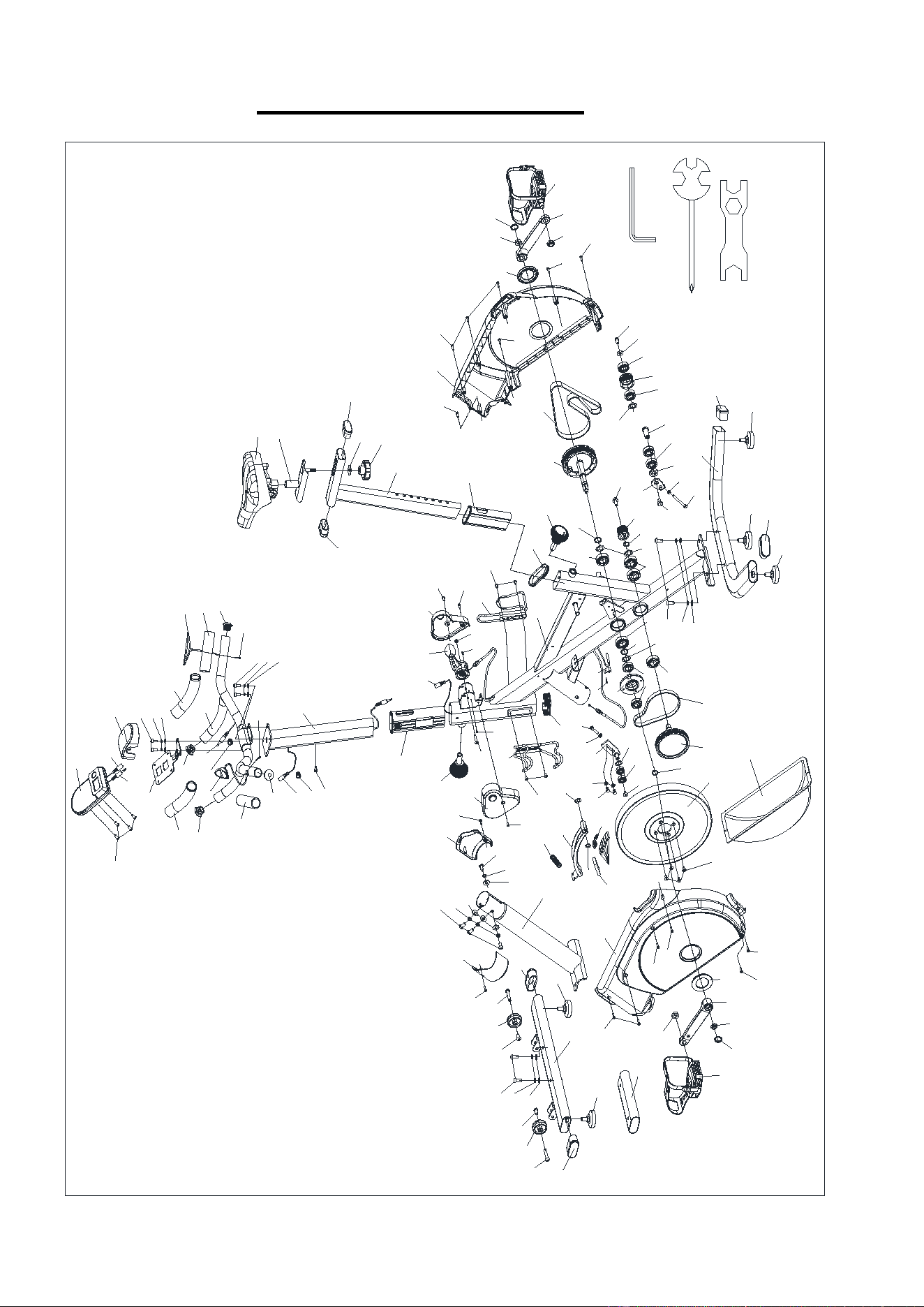
EXPLODED DIAGRAM
31
9
35
32
33
35
7
34
103
30
74
78
72
77
22
104
90
85
89
84
87
22
29
68
67
65
66
65
70
65
14
71
13
59
69
45
49
5
49
45
49
73
76
42
43
44
74
81
78
75
82
54
57
62
59
58
60
63
64
61
12
22
109
74
80
55
56
96
95
6
97
94
93
22
98
22
86
85
90
83
104
29
22
49
4
49
42
43
44
48
46
47
47
46
48
29
101
42
43
91
42
43
91
45
102
29
30
28
27
108
107
38
23
24
18
20
26
28
29
106
108
23
25
39
37
19
50
52
2
39
40
41
52
50
17
51
105
10
39
40
41
3
8
51
52
52
17
37
53
16
1
11
15
21
21
29
29
29
36
45
78
74
79
88
92
99
100
B S13-14-15 1PC
C S17-19 1PC
A S5 1PC
10a
10b
110
Version 1.0

17
