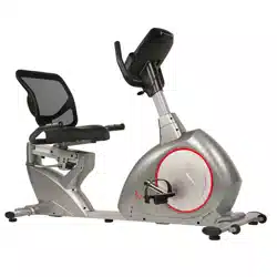
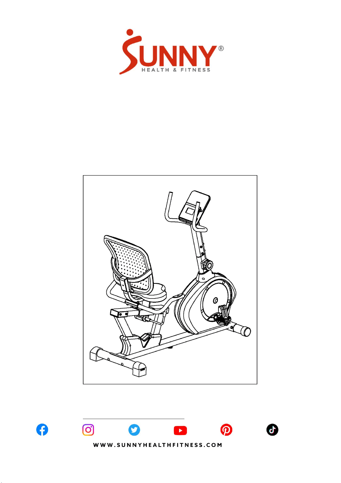
SMART HEAVY-DUTY
MAGNETIC RECUMBENT EXERCISE BIKE
WITH 350LB WEIGHT CAPACITY
SF-RB424002
USER MANUAL
IMPORTANT! Please retain owner’s manual for maintenance and adjustment instructions.
Your satisfaction is very important to us, PLEASE DO NOT RETURN UNTIL YOU HAVE
CONTACTED US: [email protected] or 1-877-90SUNNY (877-907-8669).

1
IMPORTANT SAFETY INFORMATION
We thank you for choosing our product. To ensure your safety and health, please use this
equipment correctly. It is important to read this entire manual before assembling and using the
equipment. Safe and effective use can only be achieved if the equipment is assembled,
maintained and used properly. It is your responsibility to ensure that all users of the equipment
are informed of all warnings and precautions.
1. Before starting any exercise program, you should consult your physician to determine if
you have any medical or physical conditions that could put your health and safety at risk,
or prevent you from using the equipment properly. Your physician’s advice is essential if
you are taking medication that affects your heart rate, blood pressure or cholesterol level.
2. Be aware of your body’s signals. Incorrect or excessive exercise can damage your health.
Stop exercising if you experience any of the following symptoms: pain, tightness in your
chest, irregular heartbeat, shortness of breath, lightheadedness, dizziness or feelings of
nausea. If you do experience any of these conditions, you should consult your physician
before continuing with your exercise program.
3. Keep children and pets away from the equipment. The equipment is designed for adult
use only.
4. Use the equipment on a solid, flat level surface with a protective cover for your floor or
carpet. To ensure safety, the equipment should have at least 2 feet (60 cm) of free space
all around it.
5. Ensure that all nuts and bolts are securely tightened before using the equipment. The
safety of the equipment can only be maintained if it is regularly examined for damage
and/or wear and tear.
6. Always use the equipment as indicated. If you find any defective components while
assembling or checking the equipment, or if you hear any unusual noises coming from the
equipment during exercise, discontinue use of the equipment immediately and do not use
until the problem has been rectified.
7. Wear suitable clothing while using the equipment. Avoid wearing loose clothing that may
become entangled in the equipment.
8. Do not place fingers or objects into the moving parts of the equipment.
9. The maximum weight capacity of this unit is 350 lbs (160 kgs).
10. The equipment is not suitable for therapeutic use.
11. To avoid bodily injury and/or damage to the product or property, proper lifting and moving
is required.
12. Your product is intended for use in cool, dry conditions. You should avoid storage in
extreme cold, hot or damp areas as this may lead to corrosion and other related problems.
13. This equipment is designed for indoor and home use only. It is not intended for
commercial use!
2
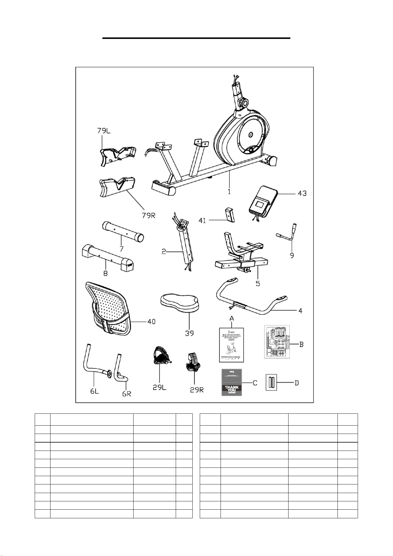
PRE-ASSEMBLY CHECK LIST
Before you start to assemble, please make sure all parts are included.
No.
Description
Spec.
Qty.
No.
Description
Spec.
Qty.
1
Main Frame
1
39
Seat
215
1
2
Handlebar Post
1
40
Backrest
KX838
1
4
Rear Handlebar
1
41
Backrest Cover
1
5
Rail
1
43
Meter
HR6035BSP
1
6L
Left Handlebar
1
79L
Left Seat Cover
1
6R
Right Handlebar
1
79R
Right Seat Cover
1
7
Front Stabilizer
Φ60X1.5X420
1
A
Manual
1
8
Rear Stabilizer
Φ60X1.5X480
1
B
Hardware Package
1
9
Adjustment Handle
1
C
Thank You Card
1
29L
Left Pedal
1/2”X20
1
D
Battery
AAA
2
29R
Right Pedal
1/2”X20
1
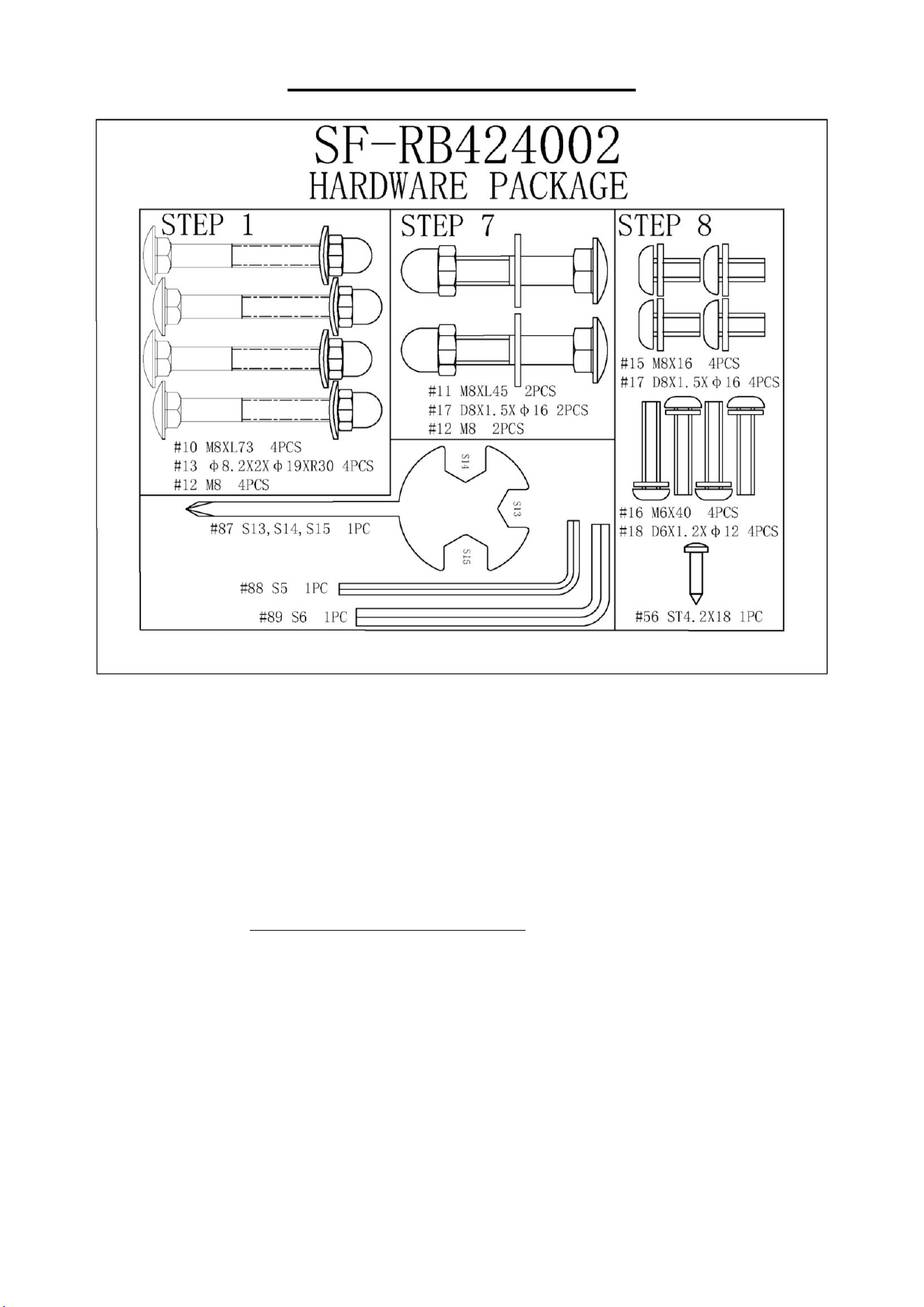
3
HARDWARE PACKAGE
Ordering Replacement Parts (U.S. and Canadian Customers only)
Please provide the following information in order for us to accurately identify the part(s)
needed:
✓ The model number (found on cover of manual)
✓ The product name (found on cover of manual)
✓ The part number found on the “EXPLODED DIAGRAM” (pages 14~15) and “PARTS LIST”
(page 13)
Please contact us at [email protected] or 1-877-90SUNNY (877-907-8669).
4
ASSEMBLY INSTRUCTIONS
We value your experience using Sunny Health and Fitness products. For assistance with parts or
troubleshooting, please contact us at suppo[email protected] or 1-877-90SUNNY
(877-907-8669).
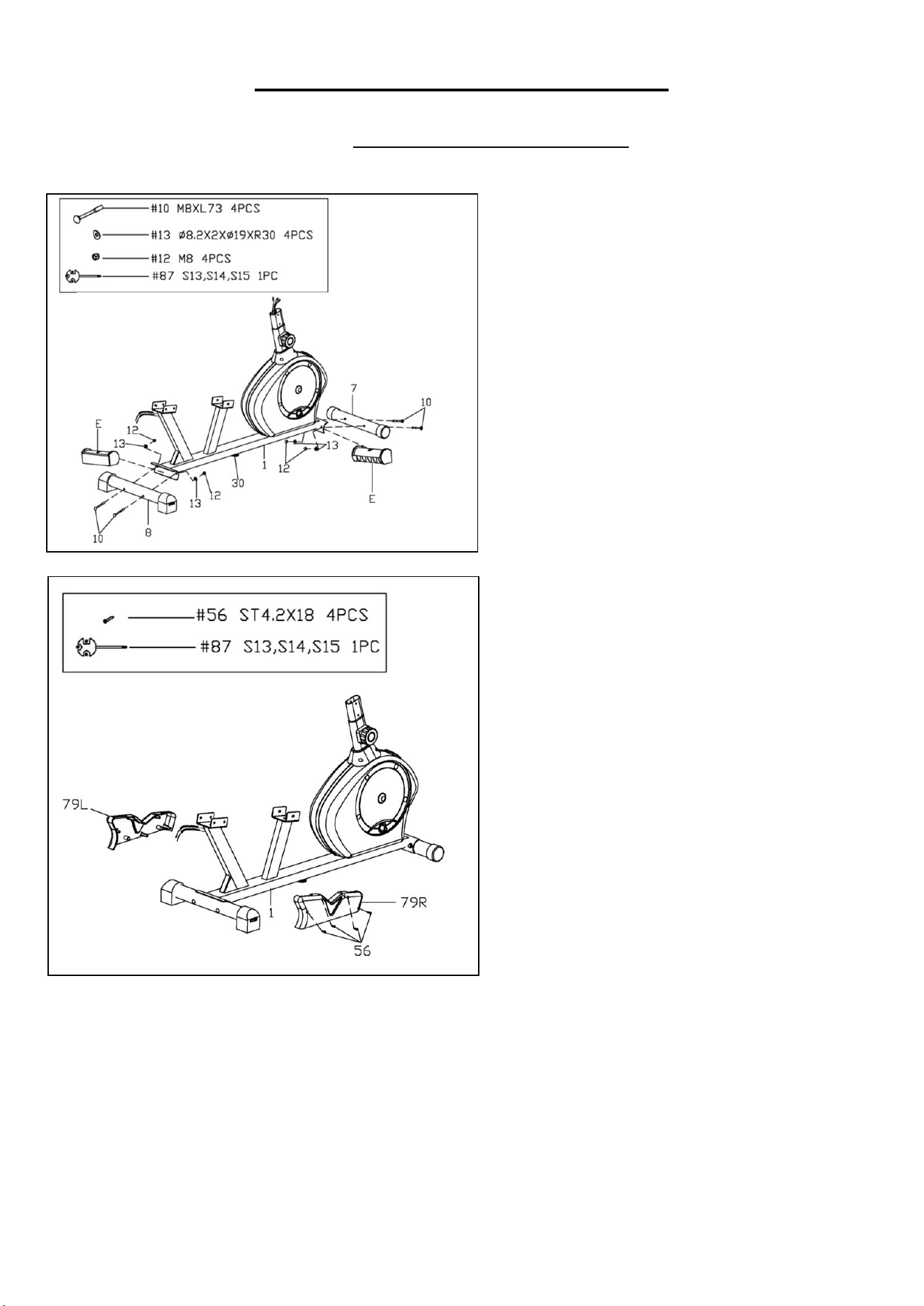
STEP 1:
Remove 2 Plastic Tubes (No. E) from the
Main Frame (No. 1).
Attach the Front Stabilizer (No. 7) and the
Rear Stabilizer (No. 8) to the Main Frame
(No. 1) with the 4 Carriage Bolts (No. 10), 4
Arc Washers (No. 13) and 4 Cap Nuts (No.
12) using Spanner (No. 87).
NOTE: Ensure that all bolts and washers are
in place and partially threaded in before
completely tightening them.
STEP 2:
Remove 4 Screws (No. 56) from the Left &
Right Seat Covers (No. 79L & No. 79R)
using Spanner (No. 87).
Attach the Left & Right Seat Covers (No.
79L & No. 79R) onto the Main Frame (No. 1)
with 4 Screws (No. 56) that were just
removed. Tighten and secure with Spanner
(No. 87).
5
We value your experience using Sunny Health and Fitness products. For assistance with parts or
troubleshooting, please contact us at suppo[email protected] or 1-877-90SUNNY
(877-907-8669).
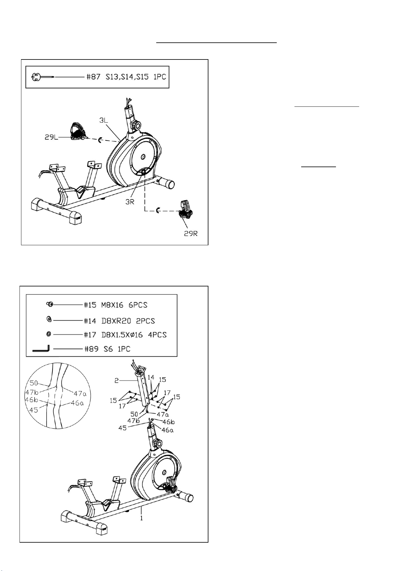
STEP 3:
Align the Left Pedal (No. 29L) with Left
Crank (No. 3L) at a 90° angle and gently
insert the pedal into the crank arm. Turn the
Left Pedal (No. 29L) counter-clockwise as
tightly as you can with your hands, then use
Spanner (No. 87) to tighten securely.
Align the Right Pedal (No. 29R) with Right
Crank (No. 3R) at a 90° angle and gently
insert the pedal into the crank arm. Turn the
Right Pedal (No. 29R) clockwise as tightly
as you can with your hands, then use
Spanner (No. 87) to tighten securely.
NOTE: Left Pedal (No. 29L) is marked with
“L” on the pedal, while Right Pedal (No.
29R) is marked with “R” on the pedal.
Attaching the Left & Right Pedals (No. 29L
& No. 29R) to the wrong Left & Right
Cranks (No. 3L & No. 3R) or turning them
with the wrong direction will damage the Left
& Right Cranks (No. 3L & No. 3R).
STEP 4:
Remove 6 Allen Bolts (No. 15), 2 Arc
Washers (No. 14) and 4 Flat Washers (No.
17) from the Main Frame (No. 1) using Allen
Wrench (No. 89).
Connect the Sensor Wire (No. 45) with the
Sensor Extension Wire (No. 50).
Connect the Pulse Extension Wire 1 A (No.
46a) with the Pulse Extension Wire 2 A
(No. 47a); connect the Pulse Extension
Wire 1 B (No. 46b) with the Pulse
Extension Wire 2 B (No. 47b).
Then attach the Handlebar Post (No. 2) to
the Main Frame (No. 1) with the 6 Allen
Bolts (No. 15), 2 Arc Washers (No. 14) and
4 Flat Washers (No. 17) that were just
removed. Tighten and secure with Allen
Wrench (No. 89).
NOTE: Ensure that all bolts and washers are
in place and partially threaded in before
completely tightening them.
NOTE: Be careful not cut or pinch any wires
when attaching the Handlebar Post (No. 2).
6
We value your experience using Sunny Health and Fitness products. For assistance with parts or
troubleshooting, please contact us at suppo[email protected] or 1-877-90SUNNY
(877-907-8669).
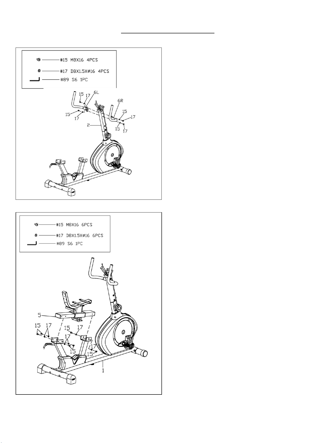
STEP 5:
Remove 4 Allen Bolts (No. 15) and 4 Flat
Washers (No. 17) from the Handlebar Post
(No. 2) using Allen Wrench (No. 89).
Attach the Left & Right Handlebars (No. 6L
& No. 6R) onto the Handlebar Post (No. 2)
with 4 Allen Bolts (No. 15) and 4 Flat
Washers (No. 17) that were just removed.
Tighten and secure with Allen Wrench (No.
89).
STEP 6:
Remove 6 Allen Bolts (No. 15) and 6 Flat
Washers (No. 17) from the Rail (No. 5)
using Allen Wrench (No. 89).
Attach the Rail (No. 5) to the Main Frame
(No. 1) with 6 Allen Bolts (No. 15) and 6
Flat Washers (No. 17) that were just
removed. Tighten and secure with Allen
Wrench (No. 89).
7
We value your experience using Sunny Health and Fitness products. For assistance with parts or
troubleshooting, please contact us at suppo[email protected] or 1-877-90SUNNY
(877-907-8669).
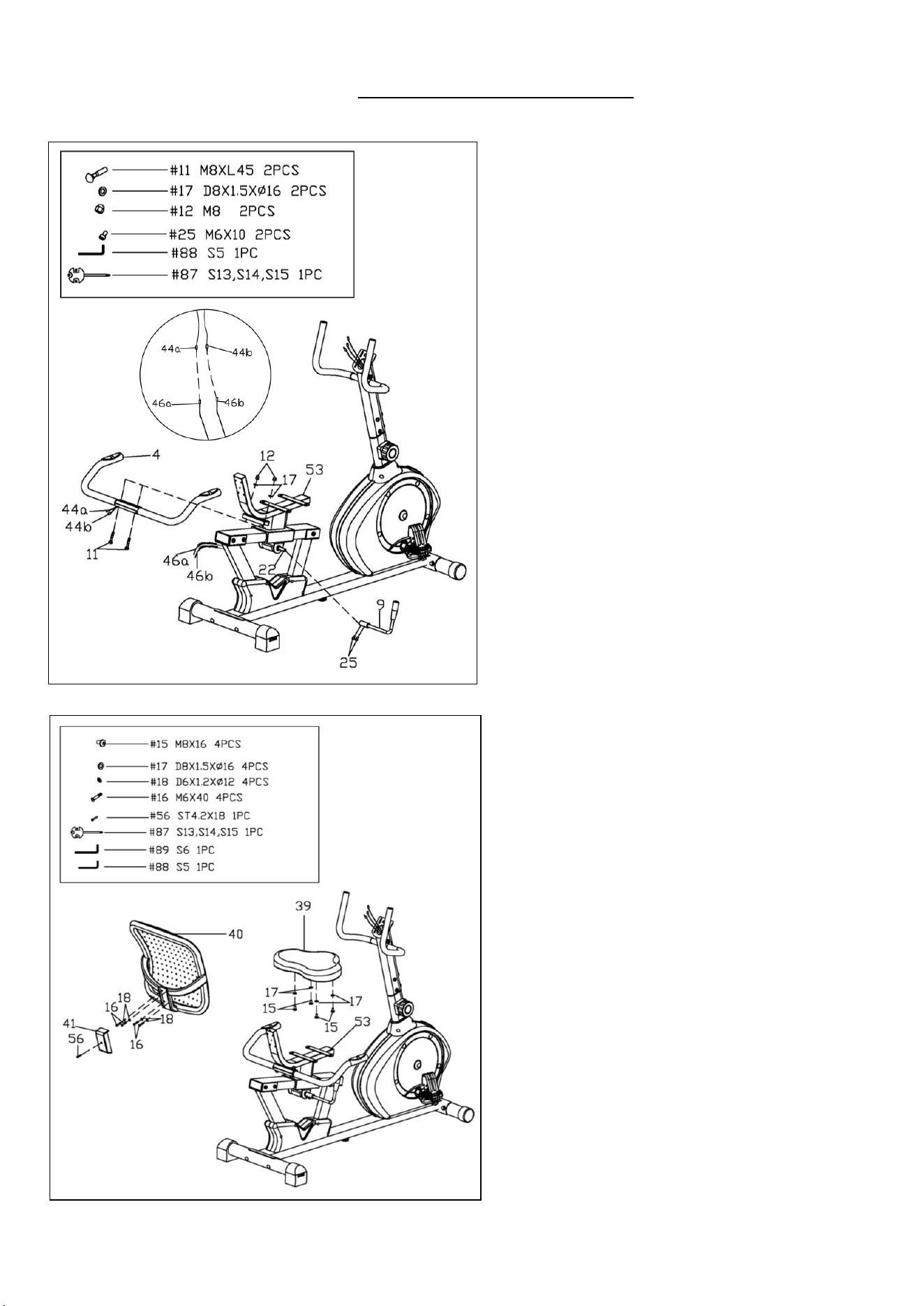
STEP 7:
First, remove 2 Allen Bolts (No. 25) from the
Adjustment Axle (No. 22) using Allen
Wrench (No. 88).
Attach the Adjustment Handle (No. 9) to the
Adjustment Axle (No. 22), and secure
tightly with the 2 Allen Bolts (No. 25) that
were just removed. Tighten and secure with
Allen Wrench (No. 88). Make sure the
Adjustment Handle (No. 9) is pointing up.
Attach the Rear Handlebar (No. 4) onto the
Seat Support (No. 53), and secure tightly
with the 2 Carriage Bolts (No. 11), 2 Flat
Washers (No. 17) and 2 Cap Nuts (No. 12)
using Spanner (No. 87).
Connect the Pulse Extension Wire 1 A (No.
46a) with the Pulse Wire A (No. 44a);
connect the Pulse Extension Wire 1 B (No.
46b) with the Pulse Wire B (No. 44b).
STEP 8:
Attach the Backrest (No. 40) to the Seat
Support (No. 53) with 4 Allen Bolts (No. 16)
and 4 Flat Washers (No. 18), tighten and
secure with Allen Wrench (No. 88).
Attach the Seat (No. 39) to the Seat Support
(No. 53) with 4 Allen Bolts (No. 15) and 4
Flat Washers (No. 17), tighten and secure
with Allen Wrench (No. 89).
Attach the Backrest Cover (No. 41) to the
Seat Support (No. 53) with Screw (No. 56),
tighten and secure with Spanner (No. 87).
8
We value your experience using Sunny Health and Fitness products. For assistance with parts or
troubleshooting, please contact us at suppo[email protected] or 1-877-90SUNNY
(877-907-8669).
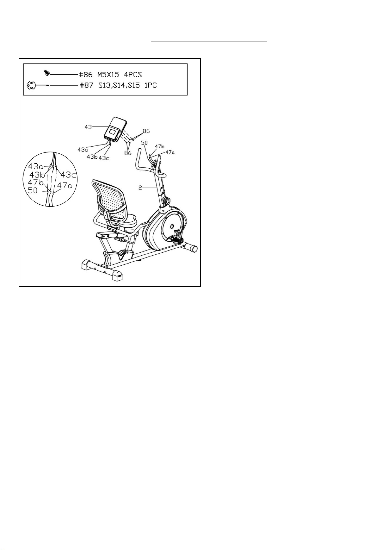
STEP 9:
Remove 4 Screws (No. 86) from the Meter
(No. 43) using Spanner (No. 87).
Connect the Sensor Extension Wire (No.
50) to the Meter Wire A (No. 43a).
Connect the Pulse Extension Wire 2 A (No.
47a) to the Meter Wire C (No. 43c); connect
the Pulse Extension Wire 2 B (No. 47b) to
the Meter Wire B (No. 43b).
Attach the Meter (No. 43) to the bracket of
the Handlebar Post (No. 2) using 4 Screws
(No. 86) that were just removed. Tighten and
secure with Spanner (No. 87).
NOTE: To avoid damaging the wires, please
push them into the Handlebar Post (No. 2)
before securing the Meter (No. 43) onto the
bracket.
THE ASSEMBLY IS COMPLETE!
9
ADJUSTMENT GUIDE
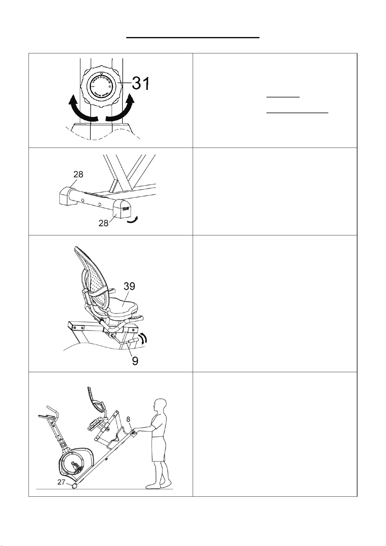
ADJUSTING THE TENSION
Adjust the tension by rotating the Tension
Controller (No. 31) clockwise to increase the
level of resistance. Rotate the Tension
Controller (No. 31) counter-clockwise to
decrease the level of resistance.
Tension levels are set at Level 1 being the
lowest and Level 15 being the highest.
ADJUSTING THE LEVEL
If at any point the bike feels uneven, you can
adjust the dials located on the side of the
Rear End Caps (No. 28).
ADJUSTING THE SEAT
To move the Seat (No. 39) forward or
backward, while seated on the recumbent
bike, put your feet on the floor. Shift the
Adjustment Handle (No. 9) up to loosen.
Adjust the Seat (No. 39) to your desired
position, then shift the Adjustment Handle
(No. 9) down to secure.
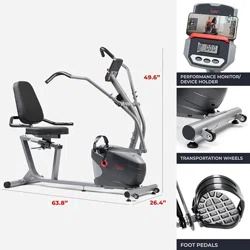
HOW TO MOVE THE RECUMBENT BIKE
There are transportation wheels located on
the Front End Caps (No. 27). Hold the Rear
Stabilizer (No. 8) and lift the recumbent bike
until the transportation wheels on the Front
End Caps (No. 27) touch the floor. Now you
can move the recumbent bike.
10
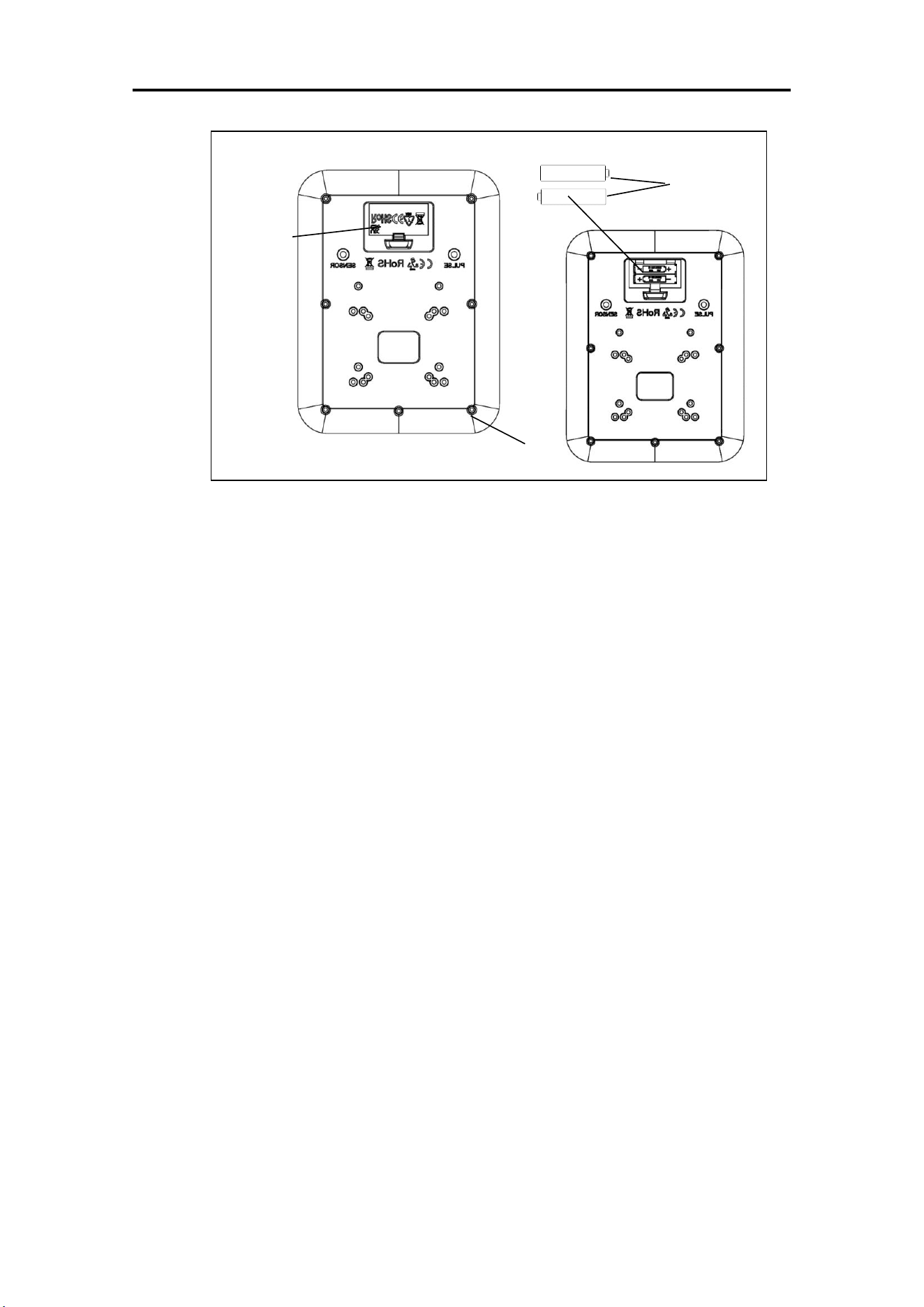
BATTERY INSTALLATION & REPLACEMENT
BATTERY INSTALLATION
1. Take out 2 AAA batteries from meter box.
2. Press the buckle of battery cover on the Meter (No. 43), then remove battery cover.
3. Install 2 AAA batteries into the battery case on the back of the Meter (No. 43). Pay attention
to the battery + and – poles before installing.
4. Press the buckle of battery cover, then put the battery cover back to the back of the Meter
(No. 43).
The installation is complete!
BATTERY REPLACEMENT
1. Press the buckle of battery cover on the back of the Meter (No. 43), then remove battery
cover.
2. Remove the 2 old AAA batteries in the battery case and install 2 new AAA batteries into the
battery case on the back of the Meter (No. 43). Pay attention to the battery + and – poles
before installing.
3. Press the buckle of battery cover, then put the battery cover back to the back of the Meter
(No. 43).
The replacement is complete!
BATTERY DISPOSAL
Dispose the batteries according to the laws and regulations of your local region. Some
batteries may be recycled. When disposing or recycling, do not mix battery types.
Battery
Cover
Battery
43

11
EXERCISE METER
SPECIFICATIONS:
TIME…………………………………..…...0:00-99:59
SPEED..……………………………………0.0-99.9 MPH
DIST (DISTANCE)………………………...0.00-999.9 M (MILES)
CAL (CALORIES)………………………….0.0-9999 KCAL
ODO (ODOMETER)……………………….0.0-9000 M (MILES)
PULSE……...............................................0-255 BPM
KEY FUNCTIONS:
MODE: Press the key to select and lock on to a particular function you want.
Press and hold the key for 2 seconds to clear data, except for ODO (ODOMETER)
when Bluetooth is not connected.
Press and hold the key for 6 seconds to disconnect from both the SunnyFit APP and
the heart rate monitor; then, the meter will enter sleep mode.
SET: Press the key to set the target values for TIME, DIST (DISTANCE), CAL (CALORIES),
PULSE.
RESET: Press the key to reset the value to zero.
NOTE: The SET & RESET keys are available when not exercising and when Bluetooth is not
connected.
OPERATION PROCEDURES:
1. AUTO ON/OFF:
The system turns on when any key is pressed or when it senses an input from the speed
sensor.
In stop mode and Bluetooth is not connected, the meter will shut off automatically and
disconnect the heart rate monitor if there is no activity for 4 minutes.
2. RESET: The unit can be reset by pressing the RESET button or changing the batteries.
3. MODE: To choose to SCAN or LOCK. If you do not want the scan mode, press the MODE
key when the pointer is on the function you want.
FUNCTIONS:
1. TIME: Press the MODE key until the pointer locks onto TIME. The total workout time will be
shown from starting exercise. In stop mode and Bluetooth is not connected, press the
MODE key to select the TIME function, then press the SET key to set a target value. The
meter will count down from the target value during exercise.
2. SPEED: Press the MODE key until the pointer locks onto SPEED. The current speed will be
shown.
3. DIST (DISTANCE): Press the MODE key until the pointer locks onto DIST (DISTANCE).
The distance of each workout will be shown. In stop mode and Bluetooth is not connected,
press the MODE key to select the DIST (DISTANCE) function, then press the SET key to
set a target value. The meter will count down from the target value during exercise.
4. CAL (CALORIES): Press the MODE key until pointer locks onto CAL (CALORIES). The
calories burned will be shown from starting exercise. In stop mode and Bluetooth is not
connected, press the MODE key to select the CAL (CALORIES) function, then press the
SET key to set a target value. The meter will count down from the target value during
exercise.
5. ODO (ODOMETER): Press the MODE key until the pointer locks onto ODO (ODOMETER).
The total accumulated distance will be shown.
6. PULSE: Press the MODE key until the pointer locks onto PULSE. User’s current heart rate
will be shown in beats per minute. Place the palms of your hands on both pulse sensors or
connect to the SunnyFit Heart Rate Monitor (HR200) and wait for 30 seconds for the most
accurate reading.
In stop mode and Bluetooth is not connected, press the MODE key to select the PULSE
function, then press the SET key to set a target value. The meter will display the target
value, even with your palms on the pulse sensors or connect to the HR200, while in stop
mode. Once you begin the workout, the meter will display the current pulse value. If your
12
pulse value surpasses the target value, the meter will “Beep“ every 5 seconds.
NOTE: This data is for reference only and cannot be used for medical treatment.
7. SCAN: Automatically cycles through functions every 6 seconds.
BATTERY: If meter display is not functioning correctly, please reinstall the batteries.
BLUETOOTH :
1. The Bluetooth icon will flash when the meter is on or wakes from sleep mode. If no
Bluetooth connection is established within 3 minutes, the Bluetooth icon will turn off.
2. The Bluetooth icon will stay on when it is connected.
WIRELESS HEART RATE
1. The wireless heart rate icon will flash when the meter is on. If the heart rate monitor is not
connected within 1 minute, the wireless heart rate icon will turn off.
2. After exercise resumes, the wireless heart rate icon will flash. If the heart rate monitor is not
connected within 1 minute, the wireless heart rate icon will turn off.
3. When the meter wakes from sleep mode, the wireless heart rate icon will flash. If the heart
rate monitor is not connected within 1 minute, the wireless heart rate icon will turn off.
4. The wireless heart rate icon will flash when the MODE key is pressed. If the heart rate
monitor is not connected within 1 minute, the wireless heart rate icon will turn off.
5. The wireless heart rate icon will stay on when the heart rate monitor is connected.
NOTE: The heart rate monitor is not included. Wireless heart rate function works with
SunnyFit Heart Rate Monitor HR200.
APP CONNECTION:
Connect Smart Equipment to SunnyFit App:
1. Scan to download SunnyFit from the app store:
2. Ensure that the Bluetooth function is turned on from your mobile device.
3. If this is your first time using the SunnyFit app, follow the in-app instructions to register
for your free SunnyFit account and log in.
4. Begin any workout activity that matches your smart equipment, then follow the onscreen
prompts to search for and connect to your smart equipment.
5. When connected, your stats and records will be displayed at the end of your
course/session, and recorded in your account profile!
Troubleshooting:
•
If you are having trouble connecting your smart equipment, visit
www.sunnyfit.com/guide or scan the QR code below:
•
If you require additional support, please contact [email protected].
13
PARTS LIST
No.
Description
Spec.
Qty.
No.
Description
Spec.
Qty.
1
Main Frame
1
44b
Pulse Wire B
650mm
1
2
Handlebar Post
1
45
Sensor Wire
600mm
1
3L
Left Crank
1
46a
Pulse Extension Wire 1 A
12100mm
1
3R
Right Crank
1
46b
Pulse Extension Wire 1 B
12100mm
1
4
Rear Handlebar
1
47a
Pulse Extension Wire 2 A
500mm
1
5
Rail
1
47b
Pulse Extension Wire 2 B
500mm
1
6L
Left Handlebar
1
48
Flat Washer
D5X20X1
1
6R
Right Handlebar
1
49
Pulse Sensor
650mm
2
7
Front Stabilizer
Φ60X1.5X420
1
50
Sensor Extension Wire
500mm
1
8
Rear Stabilizer
Φ60X1.5X480
1
51
Round Cap
Φ25X1.5
4
9
Adjustment Handle
1
53
Seat Support
1
10
Carriage Bolt
M8XL73
4
54
Magnetic Board
1
11
Carriage Bolt
M8XL45
2
55
Screw
ST4.2X30
5
12
Cap Nut
M8
6
56
Screw
ST4.2X18
30
13
Arc Washer
Φ8.2X2XΦ19XR30
4
57
Spring
58XФ14.5XФ1.6
1
14
Arc Washer
D8XR20
2
58
Magnet
40X10X25
8
15
Allen Bolt
M8X16
20
59
Nut
M6
2
16
Allen Bolt
M6X40
4
60
Nut
M5
2
17
Flat Washer
D8X1.5XΦ16
20
61
Hex Bolt
M5X60
1
18
Flat Washer
D6X1.2XΦ12
4
62
Hex Bolt
M8XL60X120
1
19
Axle Stop Ring
D12
1
63
Nylon Nut
M8
1
20
Axle Stop Ring
D10
1
64
Flange Nut
M10X1
2
21
Eccentric Gear
Φ28X60
1
65
Cone Thin Nut
M10X1XH5
2
22
Adjustment Axle
Φ12X142
1
66
Adjusting U Washer
3X30X20
2
23
Alloy Bushing
Φ14XΦ10X10
1
67
Adjusting Bolt
M6X50
2
24
Alloy Bushing
Φ18XΦ12X10
1
68
Flywheel
Φ192X45
1
25
Allen Bolt
M6X10
4
69
Flywheel Axle
Φ11.5X127
1
26
Screw
M5X30
1
70
Middle Axle
Φ17X150.5
1
27
Front End Cap
Φ60
2
71
Flange Nut
M10X1.25
2
28
Rear End Cap
Φ60
2
72
Axle Spring Washer
D17
2
29L
Left Pedal
1/2”X20
1
73
Bearing
6003RZ
2
29R
Right Pedal
1/2”X20
1
74
Allen Bolt
M6X15
4
30
Foot Pad
M10X25
1
75
Nylon Nut
M6
4
31
Tension Controller
270mm
1
76
Spring Washer
D6
4
32
Foam Grip
Φ24XT3X460
4
77L
Left Belt Cover
1
33
Square Cap
50X25X2
2
77R
Right Belt Cover
1
34
Square Cap
60X30X1.5
1
78
Disc
Φ335X25
2
35
Square Cap
80X40X2
2
79L
Left Seat Cover
1
36
Bushing
100X50X2
2
79R
Right Seat Cover
1
37
Upper Block
60X55X46
1
80
Nut Cap
M10
2
38
Grip
1
81L
Left Front Tube Cover
1
39
Seat
215
1
81R
Right Front Tube Cover
1
40
Backrest
KX838
1
82
Big Belt Pulley
Φ260
1
41
Backrest Cover
1
83
Belt
370PJ6
1
42
Wire Plug
Φ12.5
2
84
Small Belt Pulley
Φ34
1
43
Meter
HR6035BSP
1
85
Sensor Seat
1
43a
Meter Wire A
1
86
Screw
M5X15
4
43b
Meter Wire B
1
87
Spanner
S13,S14,S15
1
43c
Meter Wire C
1
88
Allen Wrench
S5
1
44a
Pulse Wire A
650mm
1
89
Allen Wrench
S6
1
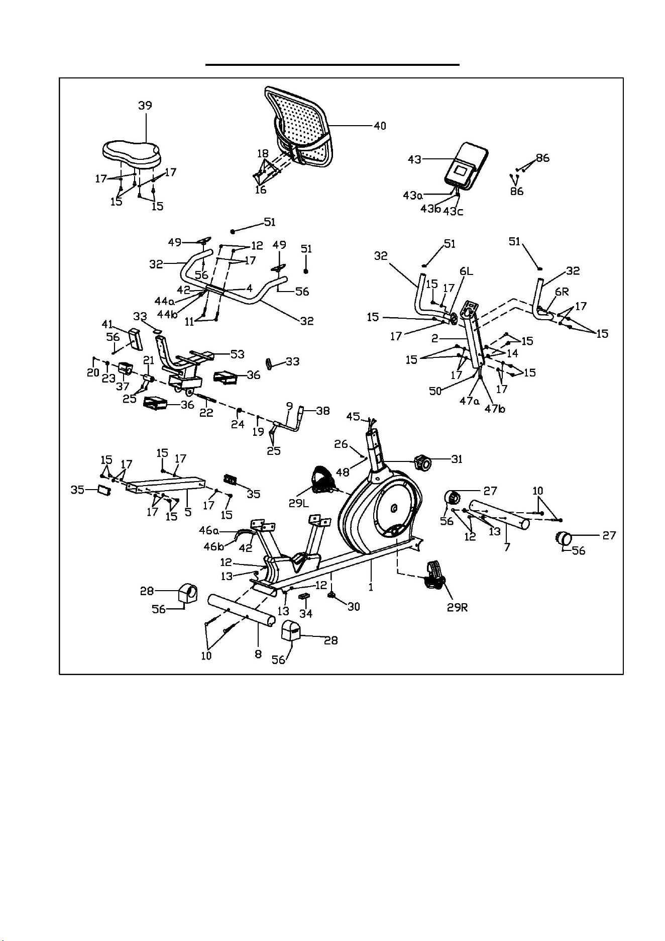
14
EXPLODED DIAGRAM 1
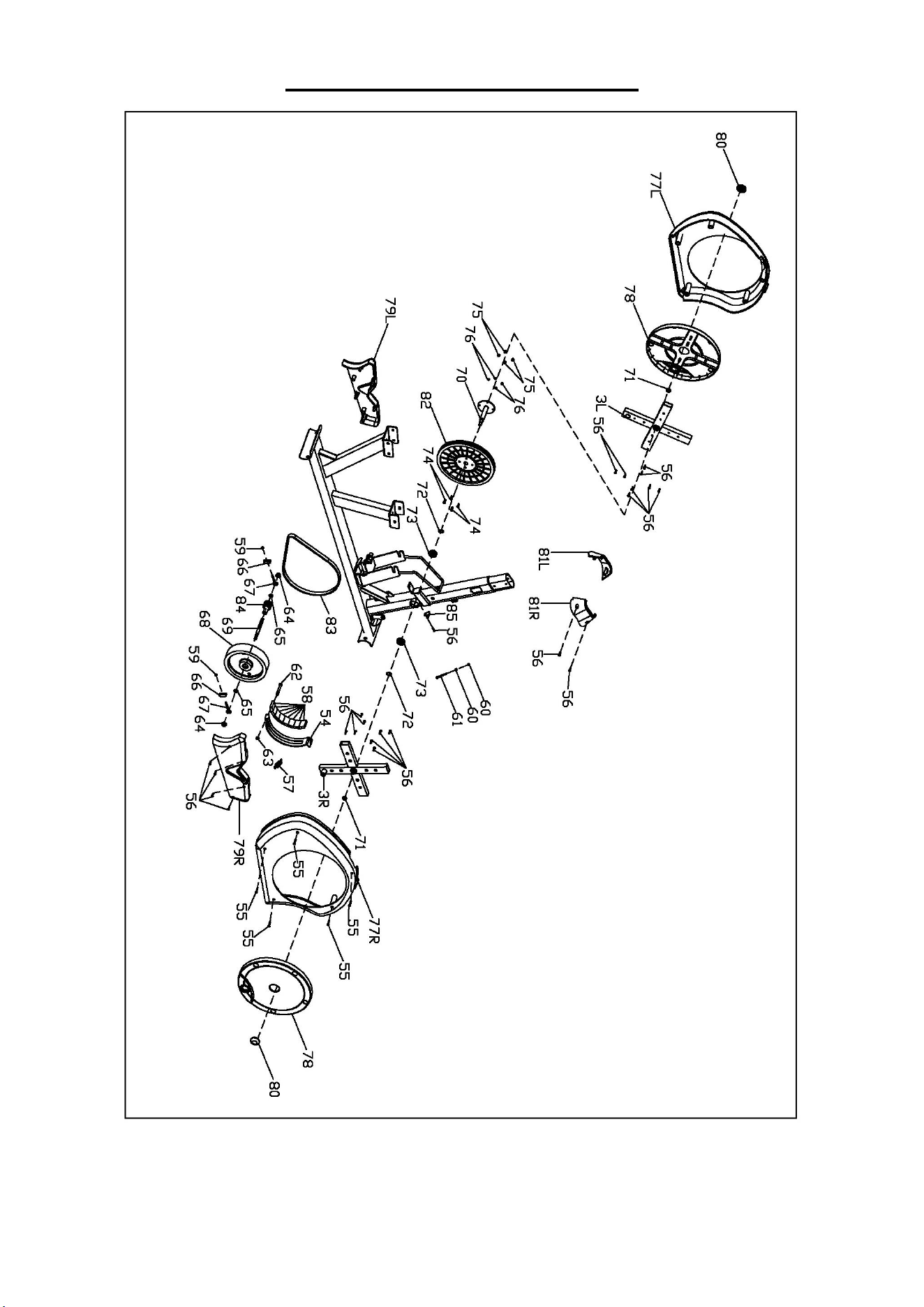
15
EXPLODED DIAGRAM 2
Version: 1.0