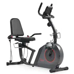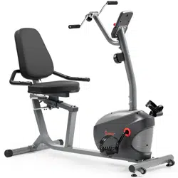
SMART MAGNETIC RESISTANCE RECUMBENT
BIKE WITH EASY ADJUSTABLE SEAT
SF-RB4616 SMART
USER MANUAL
IMPORTANT! Please retain owner’s manual for maintenance and adjustment instructions. Your
satisfaction is very important to us, PLEASE DO NOT RETURN UNTIL YOU HAVE
CONTACTED US: [email protected] or 1- 877 - 90SUNNY (877-907-8669).

1
IMPORTANT SAFETY INFORMATION
We thank you for choosing our product. To ensure your safety and health, please use this
equipment correctly. It is important to read this entire manual before assembling and using the
equipment. Safe and effective use can only be achieved if the equipment is assembled,
maintained, and used properly. It is your responsibility to ensure that all users of the equipment
are informed of all warnings and precautions.
1. Before starting any exercise program, you should consult your physician to determine if you
have any medical or physical conditions that could put your health and safety at risk or
prevent you from using the equipment properly. Your physician’s advice is essential if you are
taking medication that affects your heart rate, blood pressure, or cholesterol level.
2. Be aware of your body’s signals. Incorrect or excessive exercise can damage your health.
Stop exercising if you experience any of the following symptoms: pain, tightness in your chest,
irregular heartbeat, shortness of breath, lightheadedness, dizziness, or feelings of nausea. If
you do experience any of these conditions, you should consult your physician before
continuing with your exercise program.
3. Keep children and pets away from the equipment. The equipment is designed for adult use
only.
4. Use the equipment on a solid, flat level surface with a protective cover for your floor or carpet.
To ensure safety, the equipment should have at least 2 feet (60 CM) of free space all around
it.
5. Ensure that all nuts and bolts are securely tightened before using the equipment. The safety
of the equipment can only be maintained if it is regularly examined for damage and/or wear
and tear.
6. Always use the equipment as indicated. If you find any defective components while
assembling or checking the equipment, or if you hear any unusual noises coming from the
equipment during exercise, discontinue use of the equipment immediately and do not use
until the problem has been rectified.
7. Wear suitable clothing while using the equipment. Avoid wearing loose clothing that may
become entangled in the equipment.
8. Do not place fingers or objects into the moving parts of the equipment.
9. The maximum weight capacity of this unit is 300lbs (135kgs).
10. The equipment is not suitable for therapeutic use.
11. To avoid bodily injury and/or damage to the product or property, proper lifting and moving are
required.
12. Your product is intended for use in cool and dry conditions. You should avoid storage in
extreme cold, hot or damp areas as this may lead to corrosion and other related problems.
13. This equipment is designed for indoor and home use only; it is not intended for commercial
use.
2
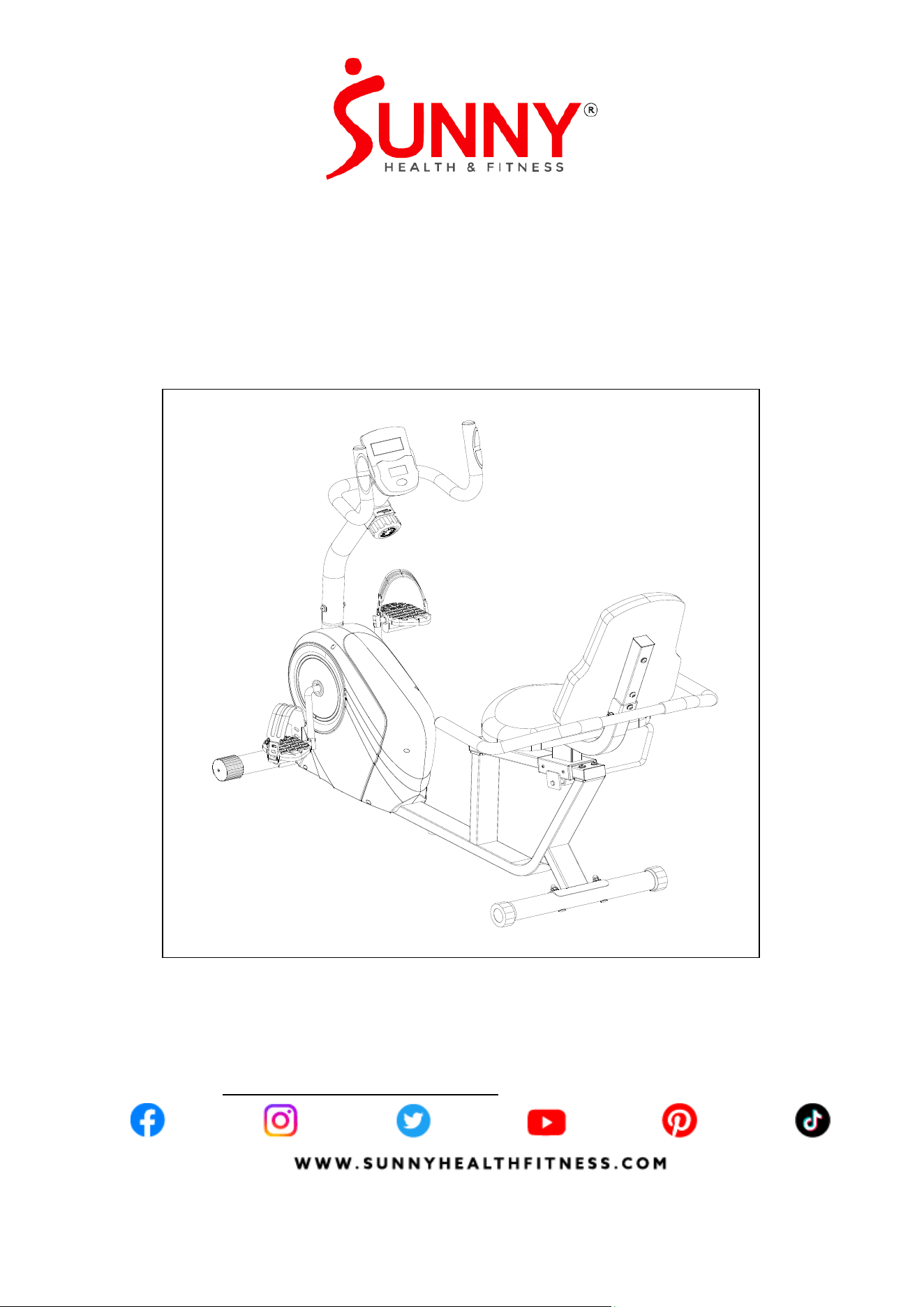
PRE-ASSEMBLY CHECK LIST
Before you start to assemble, please make sure all parts are included.
19
18
3
2
24
A
B
5
76
4
30
29
6R
6F
1
C
D
THANK
YOU
FOR YOUR PURCHASE
SF-RB4616 SMART HARDWARE PACKAGE
Step 1
Step 2
Step 4
Step 6
#53 M8 4PCS
#58 M8*65 4PCS
#54 Φ20*1.5 4PCS
#59 M8*15 4PCS
#54 Φ20*1.5 4PCS
#64 M8*25 2PCS
#66 S13-15-17 1PC
#67 S6 1PC
#68 S5 1PC
#
5
2
M
8
1
P
C
#
5
5
Φ
1
6
*
Φ
8
*
1
.
5
1
P
C
#
6
2
M
8
*
6
0
1
P
C
#
5
5
Φ
1
6
*
Φ
8
*
1
.
5
2
P
C
S
#
6
1
M
8
*
5
5
2
P
C
S
#
5
5
Φ
1
6
*
Φ
8
*
1
.
5
5
P
C
S
#
6
0
M
8
*
2
0
5
P
C
S
Step 5
#
5
5
Φ
1
6
*
Φ
8
*
1
.
5
4
P
C
S
#
7
4
M
8
*
4
5
4
P
C
S
#
8
3
M
6
*
1
2
2
P
C
S
UNNY
H E A L T H & F L T N E S S
22
SMART MAG NETIC RESISTANCE RECUMBENT
BIKE WITH EASY ADJUSTABLE SEAT↓
MPORTANT! Please retain owner’s manual for maintenance and
adju stmen t in struct ions. You r sat isfact ion is ver y impo rtant t o us,
PLEASE DO NOT RETURN UNTIL YOU HAVE CONTACTED US :
support@sunnyhealthfitness.com or 1- 877 - 90SUNNY (877-907-8669).
UNNY
H E A L T H & F L T N E S S
W W W.S U N N Y H E A L T H F I T N E S S.C O M
SF-RB4616 SMART
USER MANUAL
No. Description Spec. Qty. No. Description Spec. Qty.
1 Main Frame 1 22 Handlebar Cover 58*70*40 1
2 Front Post 1 24 Computer BJHT-060 1
3 Front Handlebar 1 29 Back Cushion 430*325*50 1
4 Seat Post 1 30 Seat 430*300*50 1
5 Rear Handlebar 1 A Manual 297*210 1
6F Front Stabilizer Φ50*1.5*370 1 B Hardware Package 340*185 1
6R Rear Stabilizer Φ50*1.5*460 1 C Thank You Card 1
18 Left Pedal 1/2"(L) 1 D Battery AAA 2
19 Right Pedal 1/2"(R) 1
3
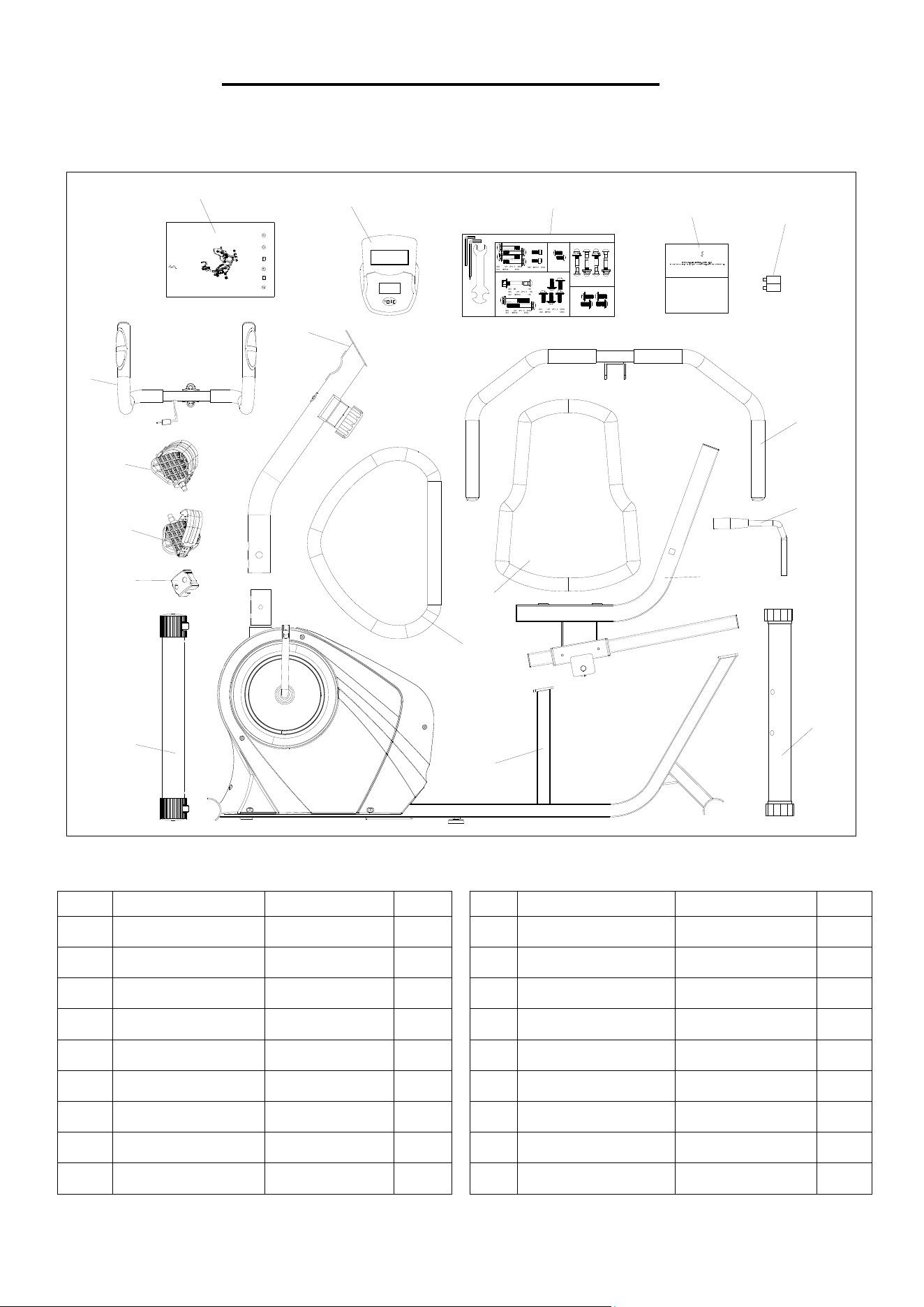
HARDWARE PACKAGE
Step 5
#
5
5
Φ
1
6
*
Φ
8
*
1
.
5
4
P
C
S
#
7
4
M
8
*
4
5
4
P
C
S
#
8
3
M
6
*
1
2
2
P
C
S
SF-RB4616 SMART HARDWARE PACKAGE
Step 1
Step 2
Step 4
Step 6
#53 M8 4PCS
#58 M8*65 4PCS
#54 Φ20*1.5 4PCS
#59 M8*15 4PCS
#54 Φ20*1.5 4PCS
#64 M8*25 2PCS
#66 S13-15-17 1PC
#67 S6 1PC
#68 S5 1PC
#
5
2
M
8
1
P
C
#
5
5
Φ
1
6
*
Φ
8
*
1
.
5
1
P
C
#
6
2
M
8
*
6
0
1
P
C
#
5
5
Φ
1
6
*
Φ
8
*
1
.
5
2
P
C
S
#
6
1
M
8
*
5
5
2
P
C
S
#
5
5
Φ
1
6
*
Φ
8
*
1
.
5
5
P
C
S
#
6
0
M
8
*
2
0
5
P
C
S
Ordering Replacement Parts (U.S. and Canadian Customers only)
Please provide the following information in order for us to accurately identify the part(s) needed:
The model number (found on cover of manual)
The product name (found on cover of manual)
The part number found on the “EXPLODED DIAGRAM” (page 12) and “PARTS LIST” (page
13~14)
Please contact us at support@sunnyhealthfitness.com or 1- 877 - 90SUNNY (877-907-8669).
4
ASSEMBLY INSTRUCTIONS
We value your experience using Sunny Health and Fitness products. For assistance with parts or
troubleshooting, please contact us at support@sunnyhealthfitness.com or 1-877-90SUNNY
(877-907-8669).
6
F
5
8
1
5
3
5
3
5
4
5
4
5
8
6
R
#66 S13-15-17 1PC
#54 φ20 *1.5 4PCS
#53 M8 4PCS
#58 M8*65 4PCS
5
3
5
4
5
3
5
4
38
38
38
59
54
59
54
59
54
70
23a
69
38
1
2
23
#67 S6 1PC
#54 φ20 *1.5 4PCS
#59 M8*15 4PCS
38
23a
23a
23a
23a
69
70
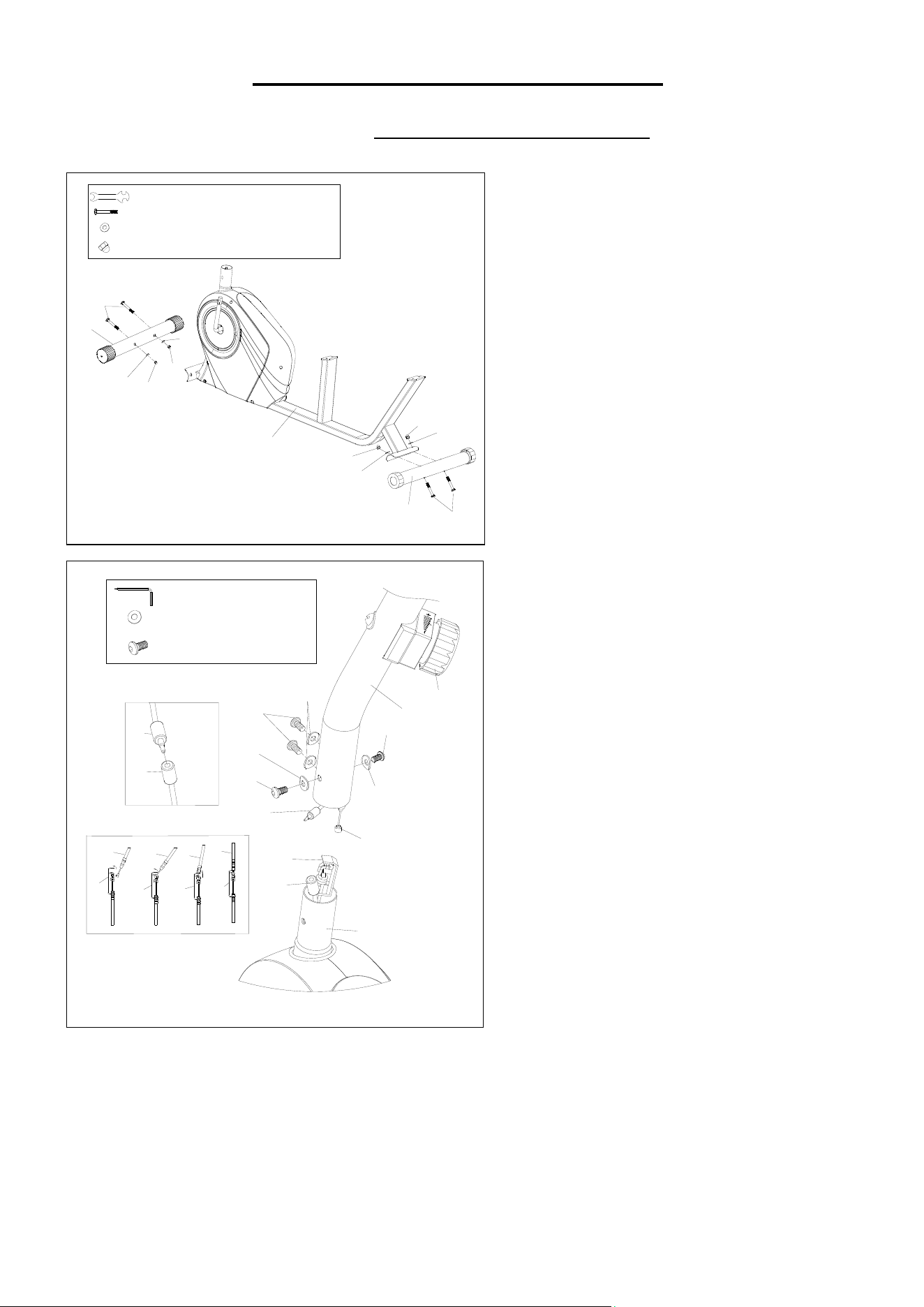
STEP 1:
NOTE:The Front Stabilizer (No. 6F) is
marked “FRONT” and the Rear
Stabilizer (No. 6R) is marked “REAR”.
Attach the Front & Rear Stabilizers
(No. 6F & No. 6R) onto the Main Frame
(No. 1) with 4 Cross Head Bolts (No.
58), 4 Arc Washers (No. 54), and 4 Cap
Nuts (No. 53). Tighten with the Spanner
(No. 66).
STEP 2:
Connect the Sensor Wire 2 (No. 70)
with Sensor Wire 1 (No. 69).
CAUTION: Please make sure the
Tension Control Knob (No. 23) is at
the highest resistance level (level 8, all
the way to the right) before you connect
the Tension Wire (No. 38).
Connect Tension Control Wire (No.
23a) and Tension Wire (No. 38). Then,
pull Tension Control Wire (No. 23a)
upward and insert it into the slot of
metal bracket on Tension Wire (No.
38). Make sure the metal fitting on
Tension Control Wire (No. 23a) is
secured in the metal bracket.
Attach the Front Post (No. 2) onto the
Main Frame (No. 1) using with 4
Hexagon Bolts (No. 59) and 4 Arc
Washers (No. 54). Tighten and secure
with the Allen Wrench (No. 67).
5
We value your experience using Sunny Health and Fitness products. For assistance with parts or
troubleshooting, please contact us at support@sunnyhealthfitness.com or 1-877-90SUNNY
(877-907-8669).
70
24
51
2
#67 S6 1PC
#51 M5*10 4PCS
70
24a
24a
24
71
19
64
22
3
2
18
10
66
66
23
66
19
10
18
10
66
# 67 S6 1 PC
# 64 M8*25 2 PCS
# 66 S13-15-17 1 PC
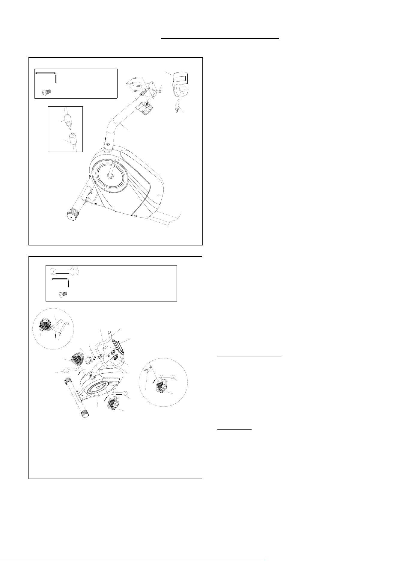
STEP 3:
Remove 4 Cross Head Screws (No. 51)
from the back of the Computer (No. 24)
using Allen Wrench (No. 67).
Connect the Sensor Wire 2 (No. 70) and
the Computer Wire (No. 24a). Then attach
the Computer (No. 24) onto the bracket of
the Front Post (No. 2) with 4 Cross Head
Screws (No. 51) that were removed.
Tighten and secure with Allen Wrench (No.
67).
STEP 4:
WARNING! Read instructions carefully as
improper assembly may cause permanent
damage to your bike.
Align the Left Pedal (No. 18) with the left
side of the Crank (No. 10) at 90°. Turn the
pedal bolt on Left Pedal (No. 18)
counter-clockwise as tightly as you can with
your hand. Then, use Spanner (No. 66) to
tighten and secure.
Align the Right Pedal (No. 19) with the right
side of the Crank (No. 10) at 90°. Turn the
pedal bolt on Right Pedal (No. 19)
clockwise as tightly as you can with your
hand. Then, use Spanner (No. 66) to
tighten and secure.
Attach the Front Handlebar (No. 3) onto
the Front Post (No. 2) with 2 Hexagon
Bolts (No. 64). Tighten with Allen Wrench
(No. 67). Then attach the Handlebar Cover
(No. 22) onto Front Handlebar (No. 3).
Plug the Pulse Wire (No. 71) to the jack on
the back of the Computer (No. 24).
6
We value your experience using Sunny Health and Fitness products. For assistance with parts or
troubleshooting, please contact us at support@sunnyhealthfitness.com or 1-877-90SUNNY
(877-907-8669).
#67 S6 1 PC
#55 φ16*φ8*1.5 4 PCS
#74 M8*45 4 PCS
#83 M6*12 2 PCS
#68 S5 1 PC
#67 S6 1PC
#55 φ16*φ8*1.5 8PCS
#60 M8*20 5PCS
#62 M8*60 1PC
#52 M8 1PC
#61 M8*55 2PCS
#66 S13-15-17 1PC
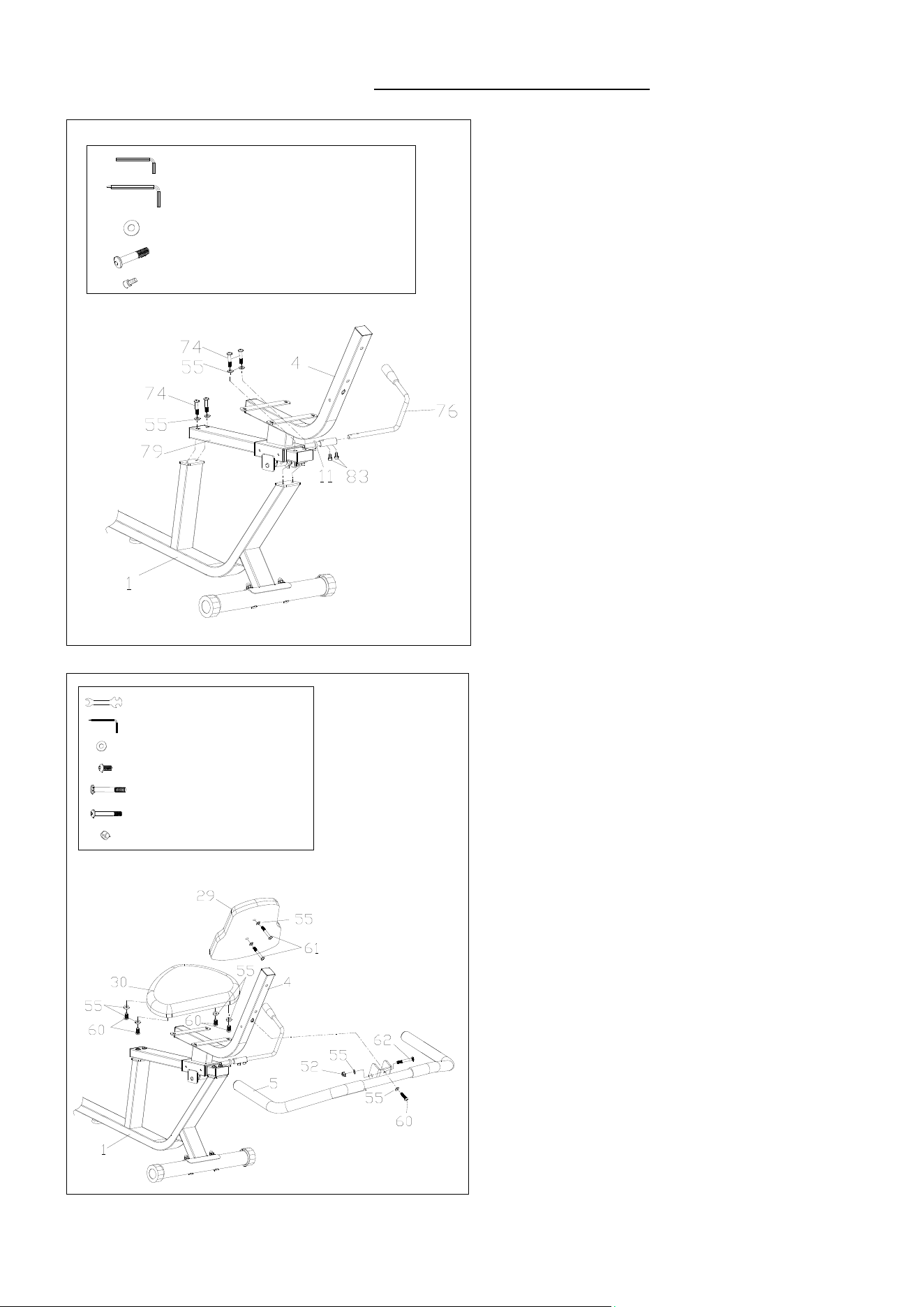
STEP 5:
Attach the Slide Rail Assembly (No.
79) to the Main Frame (No. 1), using 4
Hexagon Bolts (No. 74) and 4 Flat
Washer (No. 55) to secure and tighten
with Allen Wrench (No. 67).
Attach the Adjustable Handle (No. 76)
to the Axle (No. 11) with 2 Hexagon
Socket Bolts (No. 83). Tighten with
Allen Wrench (No. 68).
STEP 6:
Attach the Seat (No. 30) onto the Seat
Post (No. 4) with 4 Hexagon Bolts (No.
60) and 4 Flat Washers (No. 55).
Tighten with Allen Wrench (No. 67).
Attach the Rear Handlebar (No. 5) onto
the Seat Post (No. 4) with 2 Flat
Washers (No. 55), 1 Hexagon Bolt (No.
60), 1 Cross Head Bolt (No. 62) and 1
Lock Nut (No. 52). Tighten with the
Spanner (No. 66) and the Allen Wrench
(No. 67).
Attach the Back Cushion (No. 29) onto
the Seat Post (No. 4) with 2 Flat
Washers (No. 55) and 2 Hexagon Bolts
(No. 61). Tighten with the Allen Wrench
(No. 67).
The assembly is complete!
7
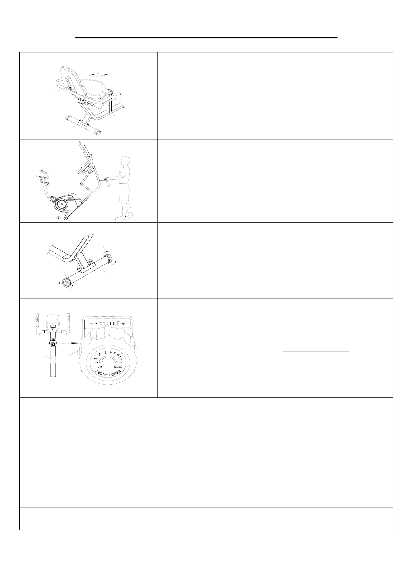
MAINTENANCE & ADJUSTMENT GUIDE
ADJUSTING THE SEAT
To adjust the Seat Post (No. 4) forward or backward, while
seated on the bike, put your feet on the floor. Shift down the
Adjustable Handle (No. 76), then slide the seat to your
desired position, lift the Adjustable Handle (No. 76) to
tighten.
MOVING THE RECUMBENT BIKE
To move the recumbent bike, hold the Rear Stabilizer (No.
6R) and tilt the recumbent bike until the End Caps (No. 31)
located on the front stabilizer touch the ground. With the End
Caps (No. 31) on the ground, you can transport the
recumbent bike to the desired location with ease.
ADJUSTING THE BALANCE
To achieve a smooth and comfortable ride, you must ensure
that the recumbent bike is stable and secure. If you notice the
recumbent bike is unbalanced during use, adjust the End
Caps (No. 25) located on the Rear Stabilizer (No. 6R) until
the recumbent bike becomes levelled with the floor surface.
ADJUSTING THE TENSION
Adjust the tension by rotating the Tension Control Knob (No.
23) clockwise to increase the level of resistance. Rotate the
Tension Control Knob (No. 23) counter-clockwise to
decrease the level of resistance.
Tension levels are set at Level 1 being the lowest and Level 8
being the highest.
CLEANING
The recumbent bike can be cleaned with a soft, clean, damp cloth. Do not use abrasives or solvents
on plastic parts. Please wipe your perspiration off the recumbent bike after each use. Be careful not
get excessive moisture on the computer display panel as this might cause electrical hazards or
electronics to fail.
Please keep the recumbent bike, especially the computer, out of direct sunlight to prevent screen
damage.
Please inspect all assembly bolts and pedals on the recumbent bike for proper tightness every
week.
STORAGE
Store the recumbent bike in a clean and dry environment, away from children.
4
76
25
6R
25
2
23
8
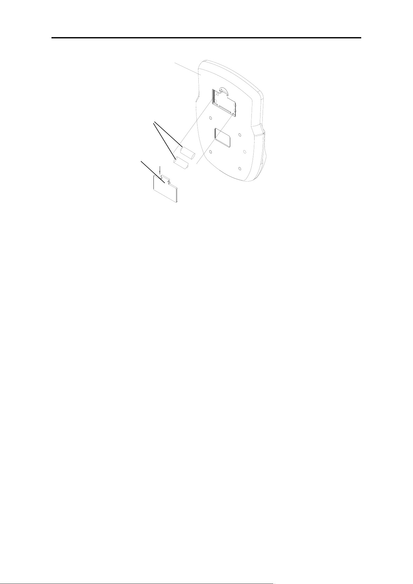
BATTERY INSTALLATION AND REPLACEMENT
BATTERY INSTALLATION:
1. Take out 2 AAA batteries from computer box.
2. Press the buckle of battery cover on the back of the Computer (No. 24), then remove battery
cover.
3. Install 2 AAA batteries into the battery case on the back of the Computer (No. 24). Pay
attention to the battery + and – ends before installing.
4. Press the buckle of battery cover, then put the battery cover back to the back of the Computer
(No. 24).
The installation is complete!
BATTERY REPLACEMENT:
1. Press the buckle of battery cover on the back of the Computer (No. 24), then remove battery
cover.
2. Remove the 2 old AAA batteries in the battery case and install 2 new AAA batteries into the
battery case on the back of the Computer (No. 24). Pay attention to the battery + and – ends
before installing.
3. Press the buckle of battery cover, then put the battery cover back to the back of the Computer
(No. 24).
The replacement is complete!
BATTERY DISPOSAL
NOTE: Always change both batteries at the same time. Do not mix battery types and do not mix
old and new batteries. Dispose batteries according to your state and regional guidelines.
Battery
Battery Cover
24
9
EXERCISE COMPUTER
BLUETOOTH :
1. The Bluetooth icon will flash when the meter is on or wakes from sleep mode. If no Bluetooth
connection is established within 3 minutes, the Bluetooth icon will turn off.
2. The Bluetooth icon will stay on when it is connected.
WIRELESS HEART RATE
1. The wireless heart rate icon will flash when the meter is on. If the heart rate monitor is not
connected within 1 minute, the wireless heart rate icon will turn off.
2. After exercise resumes, the wireless heart rate icon will flash. If the heart rate monitor is not
connected within 1 minute, the wireless heart rate icon will turn off.
3. When the meter wakes from sleep mode, the wireless heart rate icon will flash. If the heart rate
monitor is not connected within 1 minute, the wireless heart rate icon will turn off.
4. The wireless heart rate icon will flash when the MODE key is pressed. If the heart rate monitor
is not connected within 1 minute, the wireless heart rate icon will turn off.
5. The wireless heart rate icon will stay on when the heart rate monitor is connected.
NOTE: The heart rate monitor is not included. Wireless heart rate function works with SunnyFit
Heart Rate Monitor HR200. HR200 can only connect to the computer when the wireless heart
rate icon is flashing.
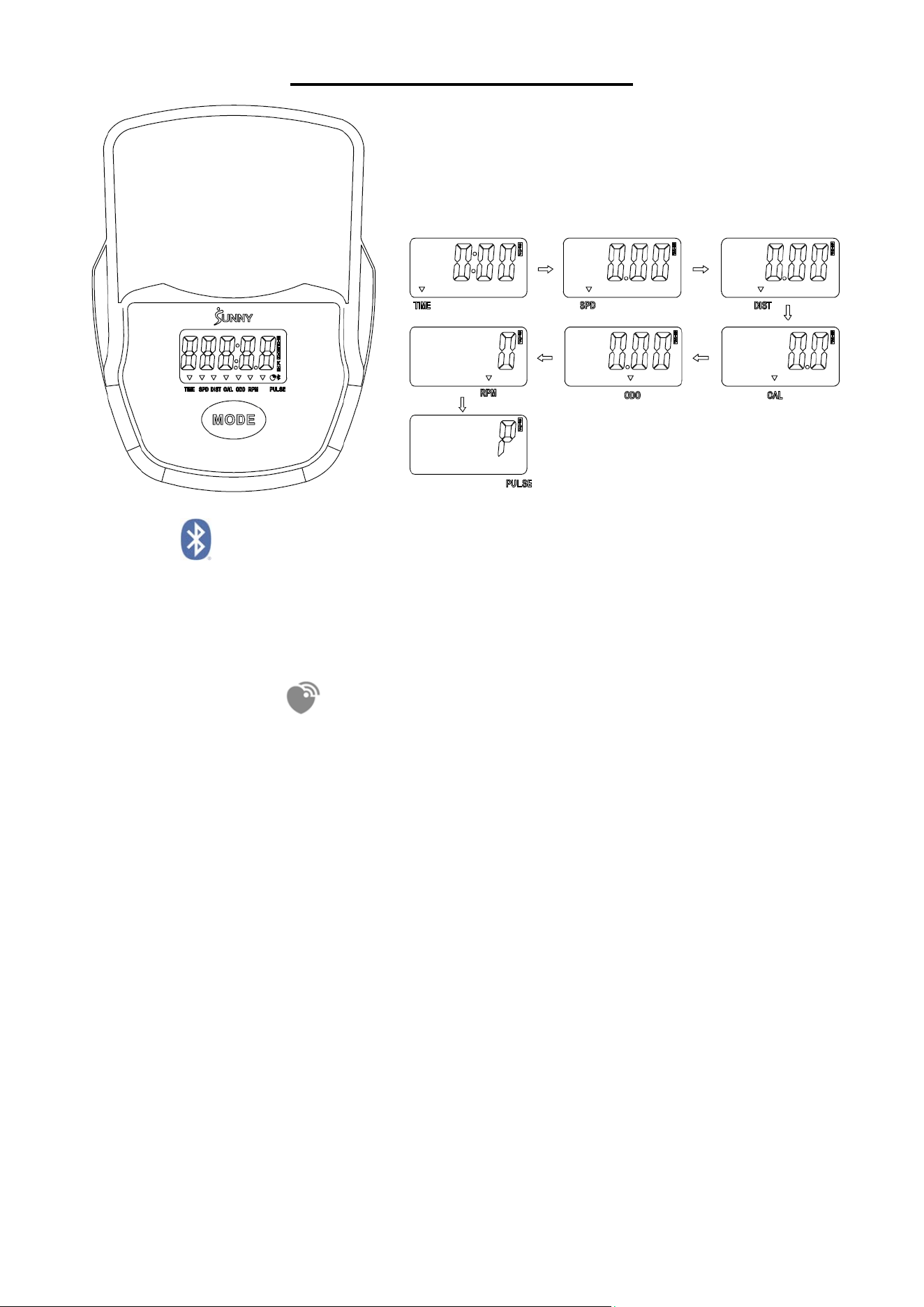
KEY FUNTION:
This key lets you to select and lock on to a particular function you want.
SCAN→TIME→SPEED(SPD) →DISTANCE(DIST) →CALORIES(CAL)→TOTAL
DIST(ODO) →RPM →PULSE
Pressing and hold with 3 seconds to reset the value to zero (without ODO) when the
Bluetooth is not connected.
Press and hold the MODE key for 6 seconds to disconnect from both the SunnyFit APP and
the heart rate monitor; then, the meter will enter sleep mode.
10
FUNCTION
SCAN: Display changes according to the next diagram every 6 seconds. and the icon will be
flash.
TIME: The total working time with starting exercise.
SPEED: The current speed with starting exercise.
DISTANCE: The current distance with starting exercise.
CALORIE: The current calorie burned with starting exercise.
TOTAL DIST (ODO): Counts the total distance with from start to finish. If the battery is
replaced, the value returns to zero.
RPM: The average number of turns per minute of the wheel to measure the speed of the
pedal.
PULSE: The current pulse rate.
SLEEP MODE
The meter will shut off automatically and disconnect the heart rate monitor if there is no
activity for 4 minutes when the Bluetooth is not connected.
The system turns on when the MODE key is depressed or a signal input from the sensor.
SPECIFICATIONS
FUNCTION
SCAN 6S
TIME 00:00-999:59(M :S)
SPEED 0.00~99.99KPH(MPH)
DIST 0.00~9999.9KM(MILES)
ODO 0.0~9999.9KM(MILE)
CAL 0.0~9999.9KCAL
PULSE RATE 40~240BPM
RPM 0~240
BATTERY SIZE-AAA, 2PCS
Operating temperature
0~40℃(32℉-104℉)
Storage temperature
-10~60℃(14℉-140℉)
APP CONNECTION:
Connect Smart Equipment to SunnyFit App:
1. Scan to download SunnyFit from the app store:
2. Ensure that the Bluetooth function is turned on from your mobile device.
3. If this is your first time using the SunnyFit app, follow the in-app instructions to register for your
free SunnyFit account and log in.
4. Begin any workout activity that matches your smart equipment, then follow the onscreen
prompts to search for and connect to your smart equipment.
5. When connected, your stats and records will be displayed at the end of your course/session,
and recorded in your account profile!
11
TROUBLESHOOTING
PROBLEM SOLUTION
There is no display on the
computer console.
1. Remove the computer and verify that the wire from the computer
is properly connected to the wire that comes from the front post.
2. Check if the batteries are correctly positioned and battery
springs are in proper contact with batteries.
3. The batteries in the computer may be unresponsive. Change to
new batteries.
The recumbent bike
wobbles when in use.
Turn the end caps on the rear stabilizer as needed to level the
recumbent bike.
The recumbent bike
makes squeaking noise
when in use.
The bolts may have become loose on the recumbent bike. Please
inspect all the bolts and tighten any loose bolts.
NOTE:
1.If you are having trouble connecting your smart equipment, visit www.sunnyfit.com/guide or
scan the QR code below:
2.If you require additional support, please contact support@sunnyfit.com
.
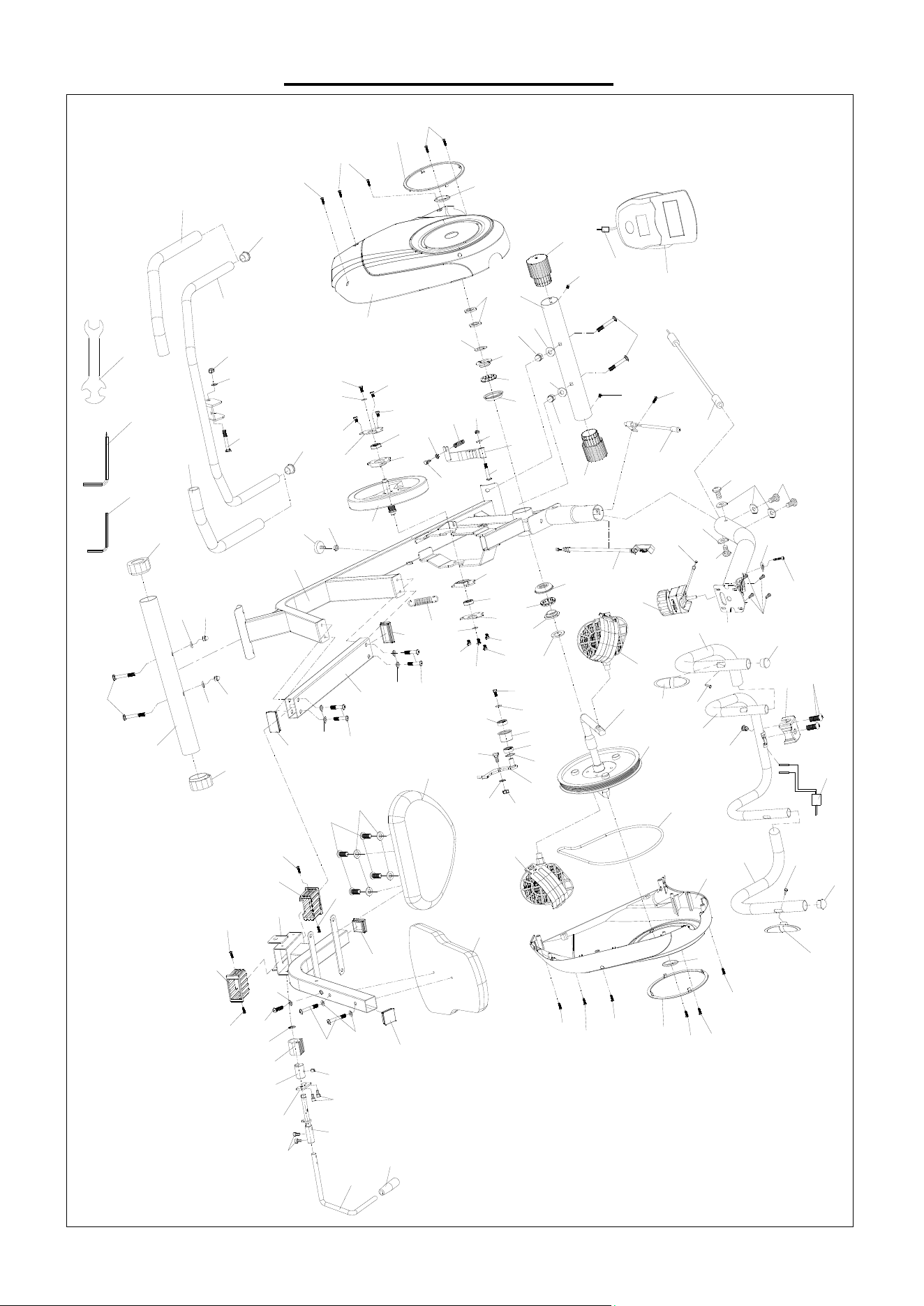
12
EXPLODED DRAWING
21
85
84
89
89
52
86
9
85
84
63
8
93
84
92
49
12
42
44
44
89
91
44
41
91
89
41
84
44
44
85
44
90
1
13
14
15
17
16
16
17
45
46
40
58
6R
25
25
53
54
53
54
32
55
60
4
35
55
60
32
29
30
37
56
87
56
56
87
56
26
19
56
56
26
27
18
64
22
3
34
28
48
20
10
39
24
31
58
53
54
53
54
6F
59
54
59
51
47
50
23
38
2
59
54
69
70
75
75
66
67
31
73
73
11
76
83
68
34
57
35
57
36
36
34
34
5
62
55
52
61
55
65
65
55
55
71
43
79
72
74
74
77
77
87
56
56
24a
88
33
78
7
78
78
78
83
80
81
82
87
23a

13
PARTS LIST
No. Description Spec. Qty No. Description Spec. Qty
1 Main Frame 1 33 Handle Grip Φ24*78 1
2 Front Post 1 34 End Cap Φ25*1.5 4
3 Front Handlebar 1 35
Handle Pulse
Sensor
110*25 2
4 Seat Post 1 36 End Cap 60*30*2.0 2
5 Rear Handlebar 1 37 Grommet Φ15*12 1
6F Front Stabilizer Φ50*1.5*370 1 38 Tension Wire 539 1
6R Rear Stabilizer Φ50*1.5*460 1 39 Spring Φ18*86.7 1
7 Idler Wheel Shaft 1 40 Circlip Φ12 1
8 Magnetic Board 1 41 Fixed Disk 72*56*1.5
2
9 Magnetic Wheel Φ230*28 3Kgs 1 42 Fixed Bolt Φ16*Φ10*25 1
10 Crank Φ16*140 1 43 Adjusting Pad M8 1
11 Axle 1 44 Hexagon Bolt M6*8 6
12 Hexagon Bolt M6*15 1 45
Locking Nut -
Right
15/16" 1
13 Hexagon Nut 7/8"L(24) 2 46 Locking Washer Φ40*T2.8 1
14 Locking Washer Φ35*T2 1 47 Step Gasket Φ25*Φ12*Φ6*1.5
1
15 Locking Nut - Left 7/8"L(24) 1 48 Ribbed Belt P320-J6 1
16
Open Face
Bearing
Φ44.5(12) 2 49 Hexagonal Nut M6 1
17 Bearing Housing Φ56.6*T16 2 50
Cross Head
Screw
M5*45 1
18 Left Pedal 1/2"(L) 1 51
Cross Head
Screw
M5*10 4
19 Right Pedal 1/2"(R) 1 52 Lock Nut M8 2
20 Belt Wheel Φ200 1 53 Cap Nut M8 4
21 Idler Wheel Φ34*Φ12、H24 1 54 Arc Washer Φ20*1.5 8
22 Handlebar Cover 58*70*40 1 55 Flat Washer Φ16*Φ8*1.5 12
23
Tension Control
Knob
Φ69*81 1 56
Cross Head
Tapping Screw
ST4.2*16 9
23a
Tension Control
Wire
L400 1 57
Cross Head
Tapping Screw
ST4.2*19 2
24 Computer BJHT-060 1 58 Cross Head Bolt M8*65 4
24a Computer Wire 1 59 Hexagon Bolt M8*15
4
25 End Cap Φ50 2 60 Hexagon Bolt M8*20
5
26 Snap Joint Φ178 2 61 Hexagon Bolt M8*55 2
27 Left Belt Cover 484*418*88 1 62 Cross Head Bolt M8*60 1
28 Right Belt Cover 484*418*88 1 63 Lock Nut M6 1
29 Back Cushion 430*325*50 1 64 Hexagon Bolt M8*25 2
30 Seat 430*300*50 1 65 Foam Grip Φ23*3*500 2
31 End Cap Φ50 2 66 Spanner S13-15-17 1
32 End Cap 38*38 2 67 Allen Wrench S6 1

14
No. Description Spec. Qty No. Description Spec. Qty
68 Allen Wrench S5 1 81 Eccentric Wheel Φ25*38 1
69 Sensor Wire 1 L=350 1 82
Hexagon Socket
Fixing Bolt
M8*12 1
70 Sensor Wire 2 L=750 1 83
Hexagon Socket
Bolt
M6*12 4
71 Pulse Wire L=650 1 84 Flat Washer Φ16*Φ6.2*1.5 4
72
Outer Hexagon
Nut
M8 1 85 Hexagon Bolt M6*10 3
73 Foam Grip Φ23*3*430 2 86 Flat Washer Φ20*Φ8.3*2.0 1
74 Hexagon Bolt M8*45 4 87
Self-Tapping
Self-Drilling
Screws
ST4.2*16 5
75 Crank Cover Φ44*10 2 88
Handle Fixing
Plate
50*25*T4 1
76 Adjustable Handle Φ12*367 1 89 Bearing 6001 4
77 Slide Rail Bushing 40*80*40 2 90
Wave Shaped
Pad
Φ16*Φ12.2*0.3 1
78
Cross Head
Tapping Screw
ST4.8*8 4 91 Fixed Seat Φ72*56*11 2
79
Slide Rail
Assembly
WELDMENT 1 92
Compression
Spring
Φ12.6*Φ0.9*39.7 1
80 Brake Block 38*34*36.2 1 93 Hexagon Bolt Φ7.9*45(M6) 1
Version:1.0

15