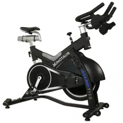
BELT DRIVE MAGNETIC INDOOR
CYCLING BIKE
SF-B1709
USER MANUAL
IMPORTANT! Please retain owner’s manual for maintenance and adjustment instructions.
Your satisfaction is very important to us, PLEASE DO NOT RETURN UNTIL YOU HAVE
CONTACTED US: [email protected] or 1-877-90SUNNY (877-907-8669).

1
IMPORTANT SAFETY INFORMATION
We thank you for choosing our product. To ensure your safety and health, please use this equipment
correctly. It is important to read this entire manual before assembling and using the equipment. Safe
and effective use can only be achieved if the equipment is assembled, maintained and used properly.
It is your responsibility to ensure that all users of the equipment are informed of all warnings and
precautions.
1. Before starting any exercise program, you should consult your physician to determine if you have
any medical or physical conditions that could put your health and safety at risk, or prevent you
from using the equipment properly. Your physician’s advice is essential if you are taking
medication that affects your heart rate, blood pressure or cholesterol level.
2. Be aware of your body’s signals. Incorrect or excessive exercise can damage your health. Stop
exercising if you experience any of the following symptoms: pain, tightness in your chest, irregular
heartbeat, shortness of breath, lightheadedness, dizziness or feelings of nausea. If you do
experience any of these conditions, you should consult your physician before continuing with your
exercise program.
3. Keep children and pets away from the equipment. The equipment is designed for adult use only.
4. Use the equipment on a solid, flat level surface with a protective cover for your floor or carpet. To
ensure safety, the equipment should have at least 2 feet (60 CM) of free space all around it.
5. Ensure that all nuts and bolts are securely tightened before using the equipment. The safety of the
equipment can only be maintained if it is regularly examined for damage and/or wear and tear.
6. Always use the equipment as indicated. If you find any defective components while assembling or
checking the equipment, or if you hear any unusual noises coming from the equipment during
exercise, discontinue use of the equipment immediately and do not use until the problem has
been rectified.
7. Wear suitable clothing while using the equipment. Avoid wearing loose clothing that may become
entangled in the equipment.
8. Do not place fingers or objects into the moving parts of the equipment.
9. The maximum weight capacity of this unit is 300 pounds (135 KG).
10. The equipment is not suitable for therapeutic use.
11. To avoid bodily injury and/or damage to the product or property, proper lifting and moving is
required.
12. Your product is intended for use in cool, dry conditions. You should avoid storage in extreme cold,
hot or damp areas as this may lead to corrosion and other related problems.
13.This equipment is designed for indoor and home use only, it is not intended for commercial use!
2
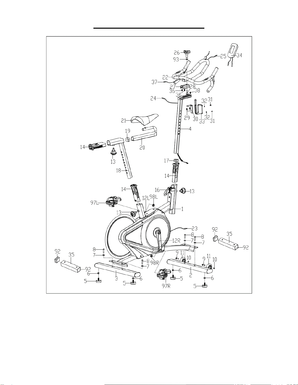
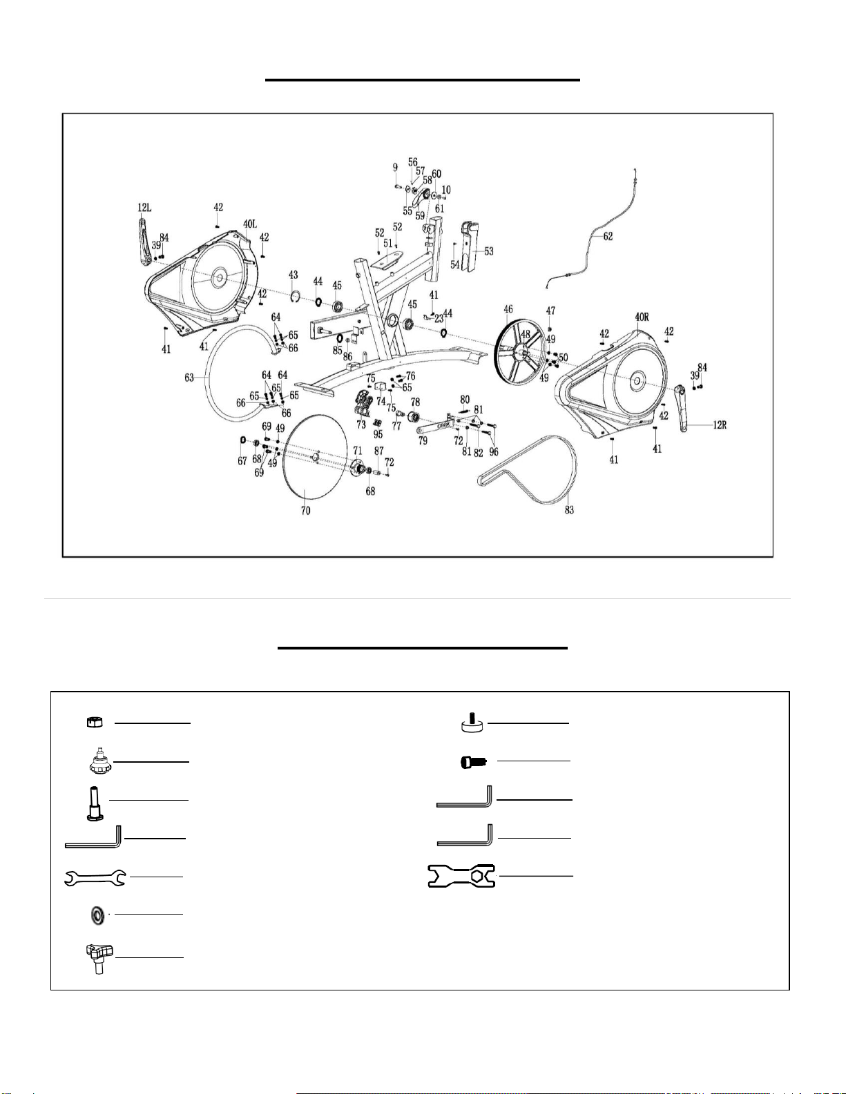
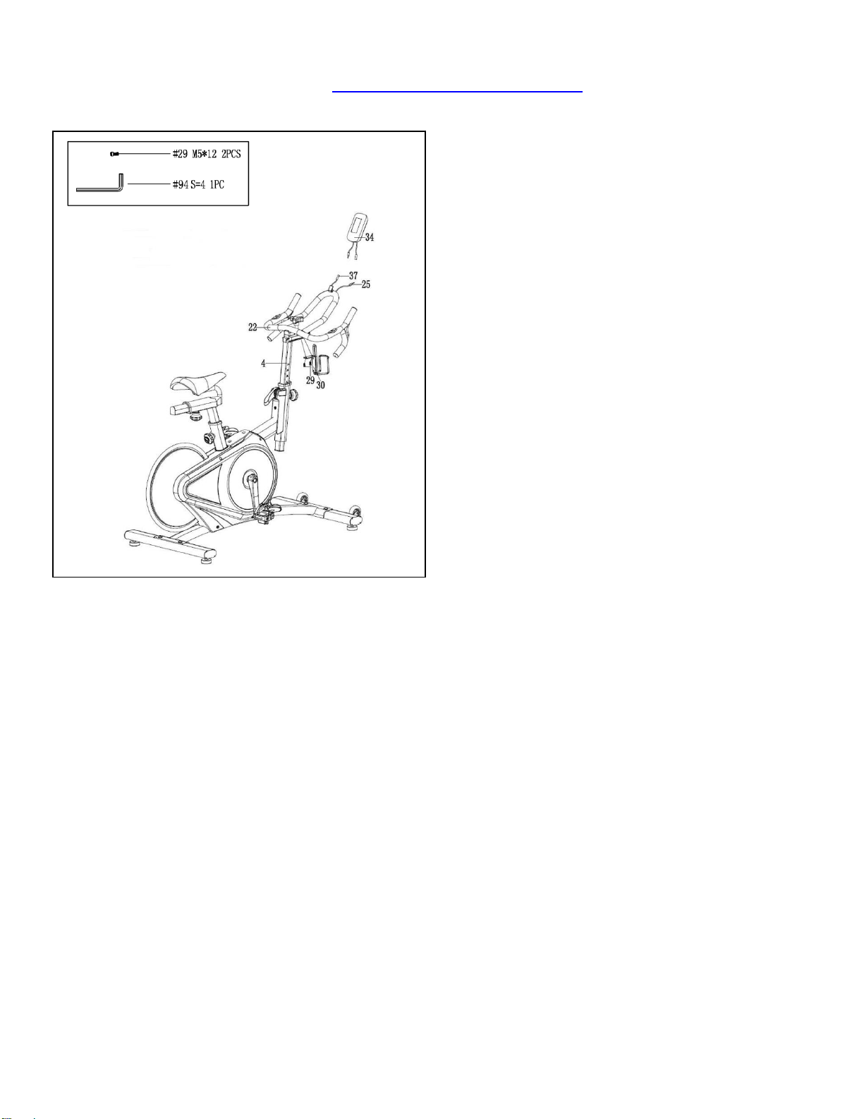
EXPLODED DIAGRAM 1
3
EXPLODED DIAGRAM 2
HARDWARE PAKAGE
#29 M5X12 2PCS
#26 1PC
#28 17.2XΦ22 1PC
#13 M16X1.5X18 3PCS
#5 2PCS
#6 M10 2PCS
#86 S5 1PC
#87 S6 1PC
#94 S4 1PC
#89 S13,15 1PC
#88 S17,19 1PC
#93 D8XΦ20*2 1PC

4
PARTS LIST
No.
Description
Spec.
Qty.
No.
Description
Spec.
Qty.
1
Main Frame
1
33
Bottle Holder
1
2
Front Stabilizer
1
34
Meter
1
3
Rear Stabilizer
1
35
Shipping Tube
2
4
Handlebar Post
1
36
Hexagon Socket Cap
Screw
M8X16
2
5
Adjusting Pad
4
37
Extension Wire 2
1
6
Hex Nut
M10
4
38
Hexagon Socket Cap
Screw
M6X10
1
7
Flat Washer
d10XΦ20X2
4
39
Flat Washer
Φ8XΦ12X1
2
8
Hexagon Socket
Head Screw
M10X25
4
40L/R
Belt Cover
1 pr.
9
Hexagon Socket
Head Screw
M8X30
3
41
Cross Head Self
Tapping Screw
5
10
Hexagon Socket
Head Screw
M6X12
3
42
Screw
6
11
Transportation
Wheel
2
43
Closing Ring
d52
1
12L/R
Crank
1 pr.
44
Axle Ring
d25
2
13
Spring Knob
M16*1.5*18
3
45
Bearing
2
14
Sleeve
3
46
Belt Pulley
1
15L/R
Refer to #97L/R
-
47
Round Magnet
1
16
Brake Handle
1
48
Center Axle
1
17
D Shape Plug
1
49
Spring Washer
D8
6
18
Seat Post
1
50
Hexagon Socket
Head Screw
M8X12
3
19
D Shape Plug
1
51
Foot Plate
1
20
Seat Horizontal
Tube
1
52
Inner Hexagon
Countersunk Head
Screw
M8X12
2
21
Seat
1
53
Brake Cover
1
22
Handlebar
1
54
Screw
M5X10
1
23
Sensor Wire
1
55
Stop Block
1
24
Extension Wire 1
1
56
Ball
1
25
Pulse Wire
1
57
Compressed Spring
1
26
Triangle Knob
1
58
Stop Block
1
27
Sliding Block
1
59
Brake Handle
1
28
Bolt
17.2XΦ22
1
60
Block
1
29
Hexagon Socket
Cap Screw
M5X12
2
61
Spacer
1
30
Bracket
1
62
Tension Wire
1
31
Cross Head Screw
M5X8
2
63
Steel Ring
1
32
Flat Washer
Φ5XΦ10X1
2
64
Hex Bolt
M6X16
5

5
65
Spring Washer
D6
7
82
Hex Bolt
M8X50
1
66
Washer
D6XΦ12X1.2
5
83
Belt
1
67
Wave Washer
D12XΦ18X0.3
1
84
Bolt
M8X18
4
68
Bearing
2
85
Stop Ring
D12
1
69
Hexagon Socket
Head Screw
M8X20
3
86
Allen Wrench
S5
1
70
Flywheel
1
87
Allen Wrench
S6
1
71
Sleeve
1
88
Wrench
S=17-19
1
72
Inner Hexagon
Countersunk Head
Screw
M8X25
2
89
Wrench
S=13-15
1
73
Brake Block
1
90
Spacer
1
74
U Shape Block
1
91
Flywheel Spacer
1
75
Cross Countersunk
Head Screw
M6X16
2
92
Square Plug
4
76
Hex Bolt
M6X12
2
93
Washer
D8XΦ20X2
1
77
Axle
1
94
Allen Wrench
S4
1
78
Idler Wheel
1
95
Rubber Cushion
1
79
Supporting Board
1
96
Hex Bolt
M8X40
2
80
Spring
1
97L/R
Pedal
1 pr.
81
Hex Screw
M8
3
98L/R
Nylon Nut
9/16
1 pr.
Ordering Replacement Parts (U.S. and Canadian Customers only)
Please provide the following information in order for us to accurately identify the part(s) needed:
✓ The model number (found on cover of manual)
✓ The product name (found on cover of manual)
✓ The part number found on the “EXPLODED DIAGRAM” and “PARTS LIST” (found near the front of
the manual)
Please contact us at [email protected] or 1- 877 – 90SUNNY (877-907-8669).
6
ASSEMBLY INSTRUCTIONS
We value your experience using Sunny Health and Fitness products. For assistance with parts or
8669).
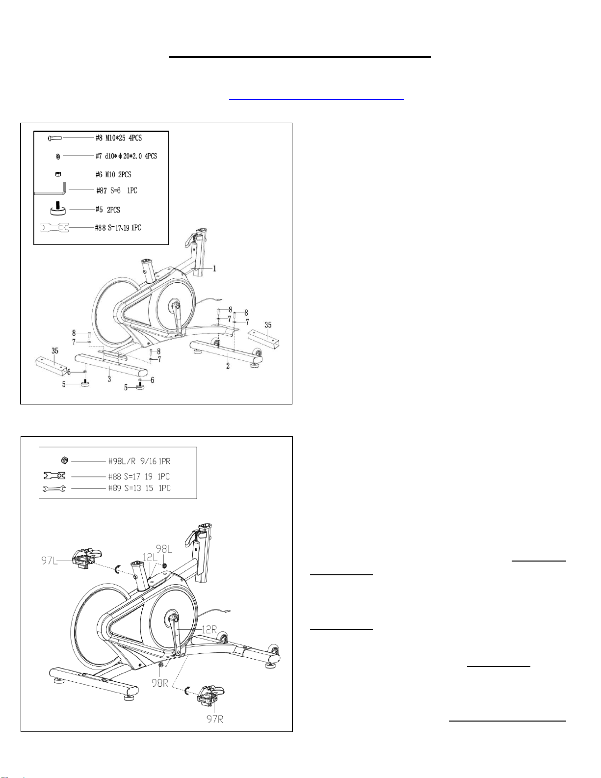
STEP 1:
Attach 2 Adjusting Pads (No. 5) and 2 Hex Nuts
(No. 6) to the Rear Stabilizer (No. 3) by using
Wrench (No. 88).
Unscrew the preassembled 4 Hexagon Socket Head
Screws (No. 8) with Allen Wrench (No. 87). Then
remove the 4 Flat Washers (No. 7) and 2 Shipping
Tubes (No. 35) from the Main Frame (No. 1).
Attach the Front & Rear Stabilizer (No. 2 & No. 3)
to the Main Frame (No. 1) using 4 Hexagon Socket
Head Screws (No. 8), 4 Flat Washers (No. 7) that
were just removed. Tighten and secure with the Allen
Wrench (No. 87).
NOTE: You can discard the Shipping Tubes (No.
35) or save them for future packaging or
transportation.
STEP 2:
IMPORTANT! Read instructions carefully. Failure
to follow instructions may cause permanent
damage to your bike.
Remove the Left & Right Nylon Nuts (No. 98L/R)
located on the Pedals (No. 97L/R). The Right Nylon
Nut (No. 98R) is white on the inside. The Left Nylon
Nut (No. 98L) is blue on the inside.
Screw the Left Pedal (No. 97L) COUNTER-
CLOCKWISE into the Left Crank (No. 12L) by using
the Wrench (No. 89). Once it is properly screwed into
the place, use the Wrench (No. 89) to hold the bolt of
the pedal and screw the Left Nylon Nut (No. 98L)
CLOCKWISE to the thread end of the Left Pedal (No.
97L) securely with Wrench(No. 88).
Screw the Right Pedal (No. 97R) CLOCKWISE into the
Right Crank (No. 12R) by using the Wrench (No. 89).
Once properly screwed into the place, use the Wrench
(No. 89) to hold the bolt of the pedal and screw the
Right Nylon Nut (No. 98R) COUNTER-CLOCKWISE
to the thread end of the Right Pedal (No. 97R) securely
with Wrench (No. 88).
7
We value your experience using Sunny Health and Fitness products. For assistance with parts or
8669).
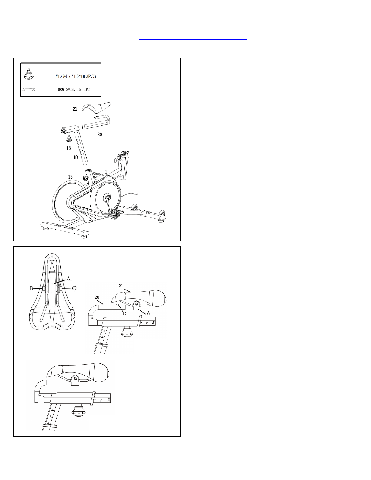
STEP 3:
Insert the Seat Post (No. 18) into the Main
Frame (No. 1). Set Seat Post (No. 18) at
desired height. Insert Spring Knob (No. 13)
and tighten to secure.
Insert the Seat Horizontal Tube (No. 20) into
the Seat Post (No. 18). Set Seat Horizontal
Tube (No. 20) at desired position. Insert Spring
Knob (No. 13) and tighten to secure.
ASSEMBLING THE SEAT
1. Use Wrench (No. 89) to loosen the 2 nuts (B
& C) on the Seat (No. 21). The round side of
the seat clamp (A) should be horizontal and on
the bottom. If it is not on the bottom, turn the
seat clamp (A), so the round side is on the
bottom. If the seat clamp (A) does not fit on the
Seat Horizontal Tube (No. 20), loosen the 2
nuts (B & C) some more. (Figure 1)
2. Slide the Seat (No. 21) onto the Seat
Horizontal Tube (No. 20). The points on the
front edge of the seat clamp (A) will go into the
indentations (D) on the Seat Horizontal Tube
(No. 20), and the V-shaped stopper at the end
of the seat clamp (A) will be in contact with the
back edge of the Seat Horizontal Tube (No.
20). (Figure 2)
3. Use Wrench (No. 89) to tighten the 2 nuts (B
& C) on the Seat (No. 21). Adjust the Seat (No.
21) so that it is leveled and not tilted forward or
backward. Continue tightening the 2 nuts (B &
C).
4. Use your hand to try to move the Seat (No.
21) forward, backward, and side to side to test if
it is secured. If the Seat (No. 21) moves, tighten
the nuts (B & C) until the Seat (No. 21) does not
move. (Figure 3)
Figure 1
Figure 2
Figure 3
8
We value your experience using Sunny Health and Fitness products. For assistance with parts or
8669).
Fig A
Fig B
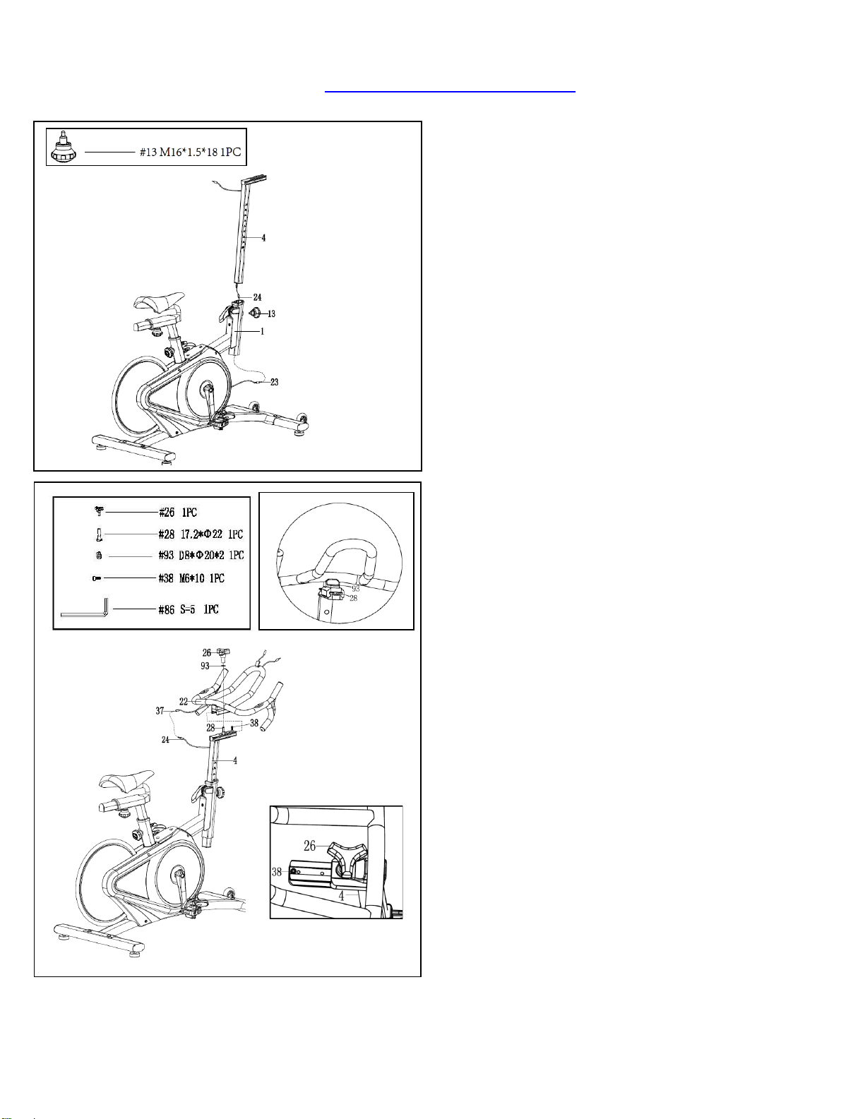
STEP 4:
Thread Extension Wire 1 (No. 24) into Main
Frame (No. 1). Insert Handlebar Post (No. 4)
into Main Frame (No. 1) and set at suitable
height. Then insert Spring Knob (No. 13) and
tighten to secure. Finally connect Extension
Wire 1 (No. 24) to Sensor Wire (No. 23).
STEP 5:
Remove Hexagon Socket Cap Screw (No. 38)
from Handlebar Post (No. 4) using Allen
Wrench (No. 86). Unscrew preassembled Bolt
(No. 28) and Washer (No. 93) from Triangle
Knob (No. 26). Place Handlebar (No. 22) on
Handlebar Post (No. 4). Do not slide all the
way on yet.
Insert Bolt (No. 28) into the hole in the
Handlebar (No. 22) from the bottom. Hold Bolt
(No. 28) on the threaded end to keep it in place
while you slide the Handlebar (No. 22) onto the
Handlebar Post (No. 4). Make sure the head of
Bolt (No. 28) fits into the groove in the
Handlebar Post (No. 4) (See Fig A). Now slide
the Handlebar (No. 22) all the way in.
Put Washer (No. 93) and Triangle Knob (No.
26) on Bolt (No. 28). Then turn the Triangle
Knob (No. 26) to tighten. Put Hexagon Socket
Cap Screw (No. 38) into the hole in the
Handlebar Post (No. 4) (See Fig B), and
tighten using Allen Wrench (No. 86).
Finally connect the Extension Wire 1 (No. 24)
and Extension Wire 2 (No. 37).
9
We value your experience using Sunny Health and Fitness products. For assistance with parts or
troubleshooting, please contact us at [email protected] or 1-877-90SUNNY (877-907-
8669).
STEP 6:
Attach the Bracket (No. 30) to the Handlebar
Post (No. 4) with 2 Hexagon Socket Cap
Screws (No. 29) using Allen Wrench (No. 94).
Connect the Extension Wire 2 (No. 37) and
Pulse Wire (No. 25) with wires from the Meter
(No. 34), then attach the Meter (No. 34) to the
Handlebar (No. 22).
Assembly is complete!
10
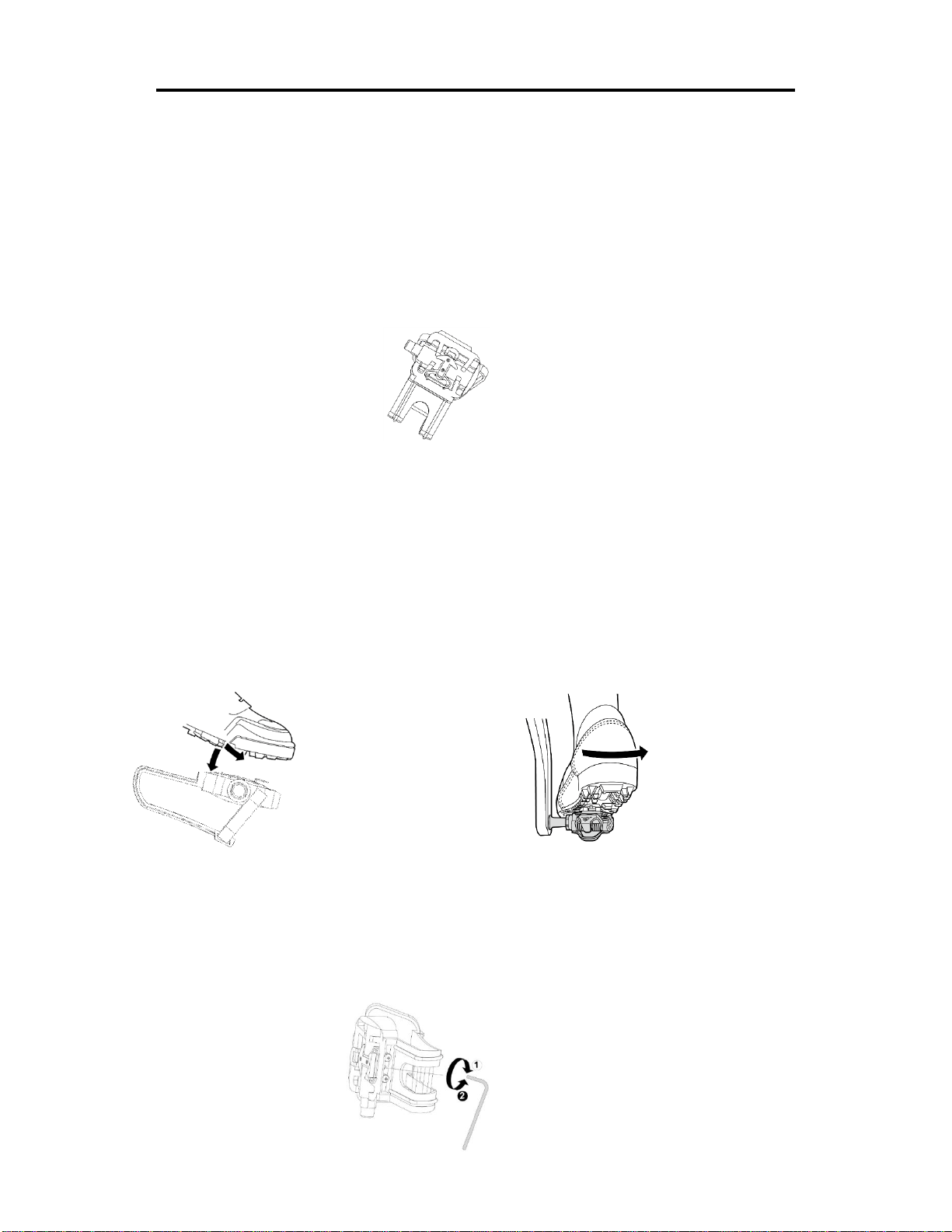
SPD TECHNICAL SERVICE INSTRUCTIONS
Caution!
Before use, read these instructions carefully.
⚫ Practice engaging and disengaging from the pedals several times in a stationary position
before riding.
⚫ Before using, lubricate the concave area of the clip.
⚫ Keep the cleat and pedal clean to ensure proper usage.
⚫ Before using, adjust the retention force of the pedal to suit your needs.
Note:
1. After tightening the cleat, practice engaging and releasing one shoe at a time.
2. Check your pedals each time before you ride the bike.
3. When the pedal starts to wear on the axle, it will not function properly. We recommend you
replace the entire pedal.
USE
Engaging Disengaging
Press the cleat into the pedal. Remove by twisting your heel to the outside.
ADJUSTING THE SPRING TENSION OF THE BINDING
The tension of the spring is adjusted for each pedal (top & bottom) with the adjustment bolt in the rear
using a 3mm Allen Wrench. Turn the bolt in a clockwise direction to increase retention force. Turn the
bolt in a counter-clockwise direction to decrease retention force.
Decrease
Increase
3mm Allen Wrench
11
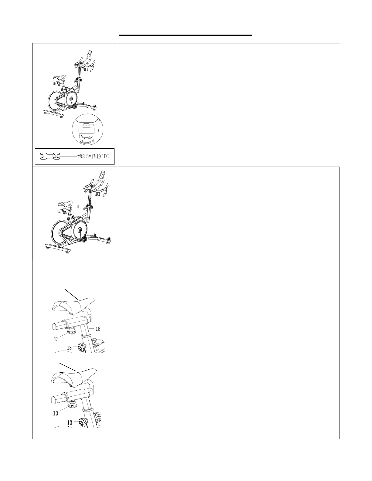
ADJUSTMENTS GUIDE
ADJUSTING THE BALANCE
In order to achieve a smooth and comfortable ride, you must
ensure that the stability of the bike is secured. If you notice that
the bike is unbalanced during use, you should adjust the foot
levelers located beneath the front and rear stabilizers. To do
so, use the Wrench (No. 88) to loosen Hex Nut (No. 6) by
turning it clockwise (direction A). With the screw loosened,
rotate Adjusting Pad (No. 5) until it sits level with the surface
that the bike is on. When you have finished adjusting the
Adjusting Pad (No. 5), use the Wrench (No. 88) to re-tighten
the Hex Nut (No. 6) by turning it counter-clockwise (direction
B). If required, repeat this process to adjust the remaining feet.
ADJUSTING THE SEAT
An appropriate seat height helps to ensure your exercise
efficiency and reduce the risk of injury. Adjusting the seat
forward or backward can help you work out different body
muscle groups.
With one pedal in the upward position, place your foot in the
toe clip and get on the bike. If your leg is bent too much, you
should move the seat up. If your foot cannot touch the pedal
or your leg is too straight, you should move the seat down.
Dismount the bike before adjusting the seat.
Loosen the [seat adjustment] Spring Knob (No. 13) to raise or
lower Seat Post (No. 18) to the desired position. Make sure
Spring Knob (No. 13) secures into the desired hole.
Loosen Spring Knob (No. 13) to move the Seat (No. 21)
forward or backward to the desired position. Once the position
is located, firmly secure Spring Knob (No. 13) by turning
clockwise.
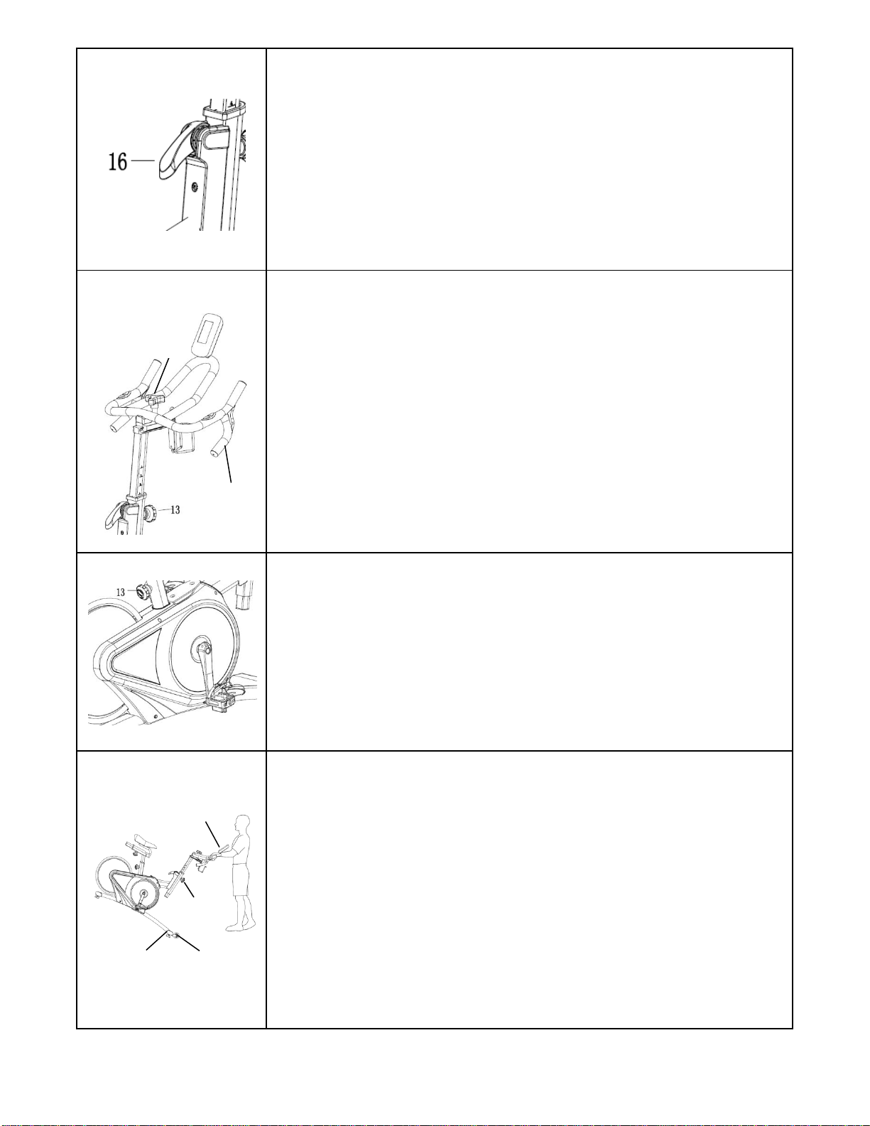
ADJUSTING THE RESISTANCE
Adjust the resistance of the bike using the Brake Handle (No.
16). Increase the level of resistance by pressing the Brake
Handle (No. 16) downward, decrease the level of resistance
by pressing the Brake Handle (No. 16) upward. Push down on
the Brake Handle (No. 16) for emergency brake.
21
21
12
DISMOUNTING THE BIKE
WARNING! Do not dismount the bike or remove your feet from
the pedals until the pedals have stopped completely. You can
stop the flywheel at any time by pushing down on Brake
Handle (No. 16).
ADJUSTING THE HANDLEBAR
Loosen the [handlebar adjustment] Spring Knob (No. 13) to
raise or lower the Handlebar (No. 22) to the desired position.
Make sure the Spring Knob (No. 13) settles into the desired
hole and secure it firmly by turning clockwise.
Loosen Triangle Knob (No. 26) to move the Handlebar (No.
22) forward or backward to desired position. Tighten the
Triangle Knob (No. 26) to secure.
ADJUSTING THE PEDAL STRAP
Place the ball of each foot in the toe clips so the front of your
shoe fits snugly in the toe clip cage. Rotate one foot to within
arm’s reach and pull the strap until the top clip cage fits your
shoe snugly. Insert the strap back into the hoop of the toe clip.
Repeat this for the other foot.
MOVING THE BIKE
To move the bike, first ensure that the Handlebar (No. 22) is
properly secured. If the Handlebar (No. 22) is loose, tighten
the Spring Knob (No. 13) to secure it. Next, stand at the front
of the bike so that you’re directly in front of the Handlebar (No.
22). Firmly grasp and hold each side of the Handlebar (No. 22),
place one foot on the front stabilizer and tilt the bike towards
you until the Transportation Wheels (No. 11) on the Front
Stabilizer (No. 2) touch the ground. With the Transportation
Wheels (No. 11) on the ground, you can transport the bike to
the desired location with ease.
26
22
22
13
2
11

13
MAINTENANCE INSTRUCTIONS
This is general information for daily, weekly and monthly maintenance to be performed on your bike.
DAILY MAINTENANCE
After each exercise session, wipe down all
the equipment: seat, frame, and handlebars.
Pay special attention to the seat post,
handlebar post and belt/chain guard. Sweat
is very corrosive and may cause problems
that require parts replacement later.
1.
Get on the bike and engage the drive
train.
2.
Pay attention to any vibrations felt
through the pedals. If you feel any
vibrations, you may need to tighten the
pedals, bottom bracket, or adjust the drive
belt/chain tension.
3.
Use a wrench to tighten the pedals until
they are secure.
MONTHLY MAINTENANCE
1.
Check all hardware is secure, such as: water
bottle holder, flywheel nuts, belt/chain guard
bolts, brake caliper lock nuts and brake
caliper tension rod nuts.
2.
Inspect the brake tension rod for signs of
wear such as missing threads. Clean and
lubricate the brake tension rod.
3.
Clean and lubricate the seat post, handlebar
post and seat slider. Remove any buildup of
foreign material.
WEEKLY MAINTENANCE
1.
Inspect moving parts and tighten the
hardware.
2.
Inspect pull pin frame fittings, making
sure the fittings are snug. Loose frame
fittings may strip out threads over time
and cause extensive damage.
3.
Clean and lubricate pop pin assemblies.
Pull on the pin and spray a small amount
of lubricant onto the shaft.
4.
Tighten the seat hardware, to make sure
the seat is level and centered.
5.
Brush and treat the resistance pads.
Remove any foreign material that may
have collected on the pads. Spray the
pads with silicone lubricant. This helps to
reduce noise from friction between the
pads and the flywheel.
6.
Visually inspect the bottom bracket, toe
clips and toe straps. If any of them are
loose or disconnected, attach and tighten.
LEATHER BRAKE PAD CARE (If Applicable)
1.
Perform this maintenance when the brake
pad is first installed and for the life of the
brake pad. Following these simple guidelines
can increase the life of your brake pads.
2. Some brake pad assemblies are pre-
lubricated. Squeeze the brake pad. If
lubricant is released, then the pad has been
pre-lubricated.
3.
If the brake pad is dry, then coat the brake
pad with 3-n-1 oil. Brush the leather with a
clean, wire bristle brush, and then apply the
oil. The oil should be allowed to soak in to
the pad. Repeat 4-5 times until the pad is
saturated, but not dripping with oil. When the
pad is saturated, it will no longer absorb oil.
4.
Inspect the brake pad weekly and lubricate if
needed. The pad should not have a glazed
appearance. If the pad appears glazed, then
brush it with wire brush and apply lubricant
as needed. If any of the sponge padding is
showing through the leather pad, the brake
pad should be replaced.
14
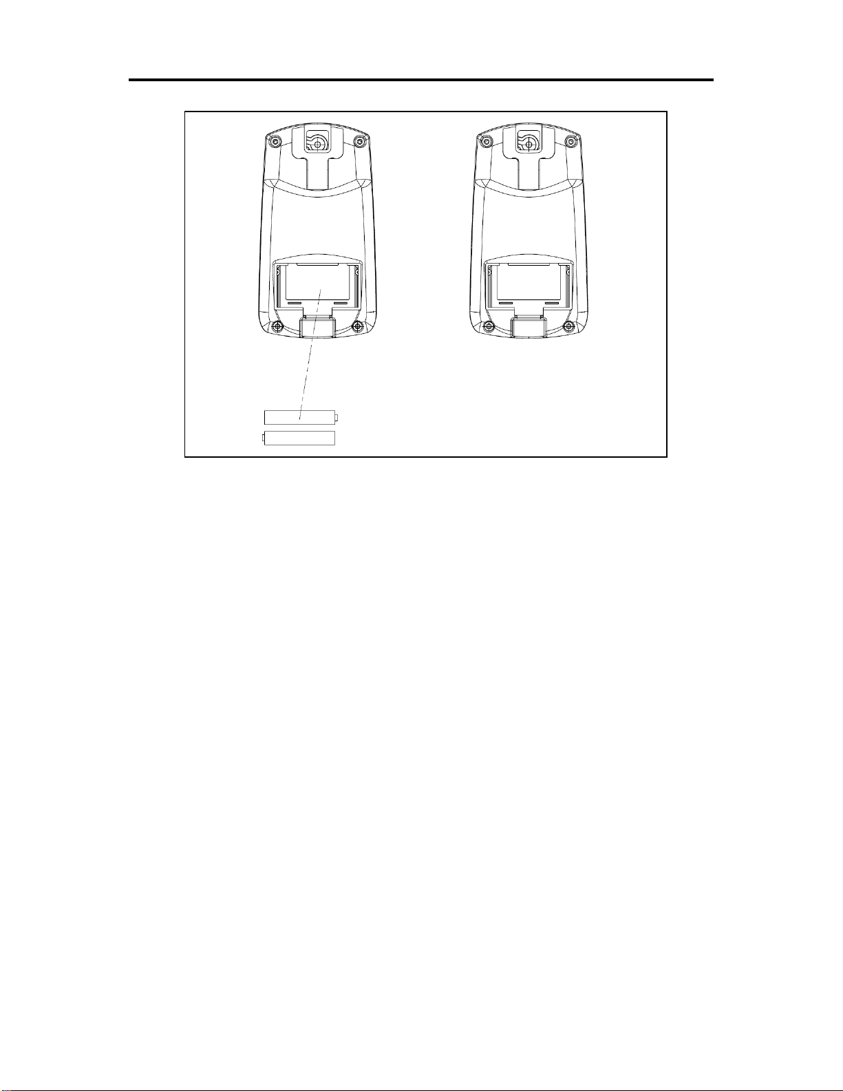
BATTERY INSTALLATION & REPLACEMENT
BATTERY INSTALLATION
The meter uses 2 AAA batteries. Open the battery cover from the back of meter, then put 2
batteries into the battery compartment. Make sure the (+) and (-) ends of the batteries are in the
correct position. Put the battery cover back.
BATTERY REPLACEMENT
If there is a problem with the display, try changing the batteries first. Open the battery cover,
remove the old batteries, and replace with new batteries. Make sure the (+) and (-) ends of the
batteries are in the correct position. Put the battery cover back. When changing batteries,
always replace both with new batteries. Do not mix old and new batteries.
15
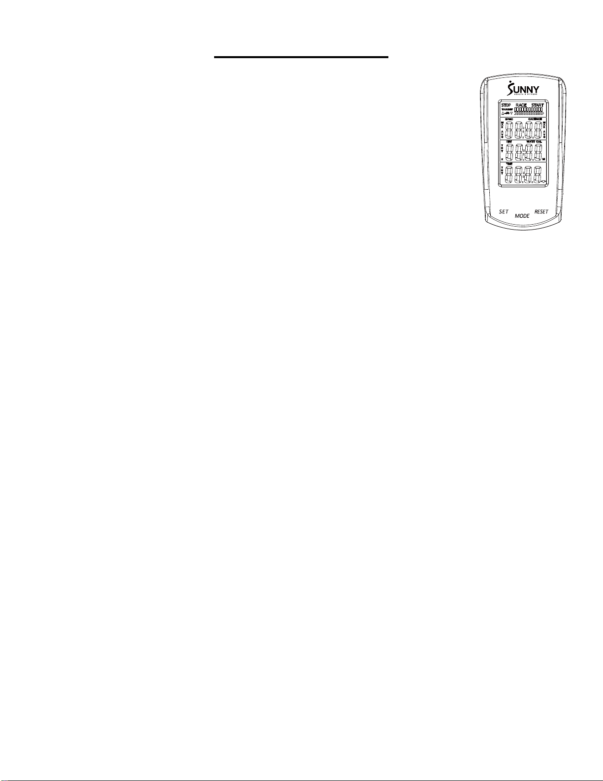
EXERCISE METER
FUNCTION BUTTONS
MODE:
Press to select the function displayed or enter value during setting mode.
Press and hold for 2 seconds to enter the RACE MODE interface during stop mode.
SET:
To set up the target value of TARGET, TIME, DIST, CAL.
Press the button and hold for 2 seconds to speed up the increment during
stop mode.
RESET:
Press the button to reset function value during setting mode.
Press the button and hold for 2 seconds to reset all value to zero.
(When the user replaces the batteries, all values will reset to zero.)
FUNCTIONS:
SPEED: Displays the speed from 0 to 99.9 KPH or MPH.
AVG SPEED: Displays the average speed only in STOP mode.
MAX SPEED: Displays the maximum speed only in STOP mode.
CADENCE (RPM): Displays the frequency per minute from 0 to 999.
AVG CADENCE (AVG RPM): Displays the average cadence (RPM) in STOP mode.
MAX CADENCE (MAX RPM): Displays the maximum cadence (RPM) in STOP mode.
DISTANCE (DIST): Accumulates total distance from 0.0 to 999.9 KM or Miles. User can preset
TARGET DISTANCE by pressing MODE & SET.
TARGET DISTANCE (TGT DIST): Users can preset the Distance in the TARGET mode.
CALORIES (CAL): Accumulate total Calories from 0.0 to 9999. User can preset target calories.
RACE: Exercise in the TARGET MODE.
TIME: Accumulates total time from 00:00 to 99:59. User can preset target Time.
TARGET TIME: Users can preset the Time in the TARGET MODE.
PULSE: Display the current pulse rate.
16
MILES OR KILOMETERS SETTING:
The default setting is miles. Press and hold SET and MODE together for 2 seconds to change to
kilometers.
SET TARGET VALUES:
1. Press SET to select a target value. CADENCE will start to flash.
2. Press and hold SET and the value will increase continuously.
3. Press MODE to enter.
4. TIME will flash.
5. Press SET to select a value.
6. Press MODE to enter.
7. Repeat to select values for DIST and CAL.
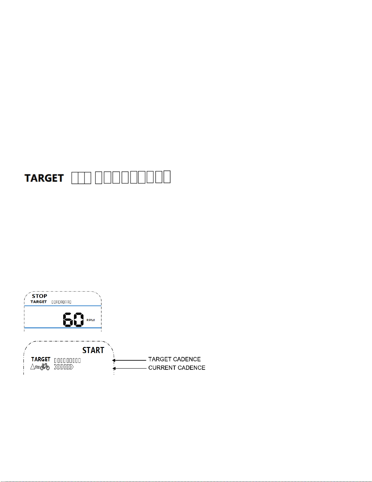
1. TARGET: the preset CADENCE.
2. In STOP mode, press SET button to enter the TARGET setting in stop mode. Press SET to
increase the CADENCE five at a time. The setting change is 15 →20→ ……110→115→120→15→
20→……→115→120→ 15 →20→ ……
3. The setting range of 15 -120 (Preset value is 60 CADENCES which equals six bars).
4. Each bar equals 10 CADENCE. Total is 12 bars.
When Current CADENCE is less than Target CADENCE,
the up arrow next to the bicycle will be displayed.

17
Each arrow equals 10 CADENCES (1-10 CADENCES displays one arrow, 11-
20 displays two). The maximum arrows displayed is 12.
This down arrow next to the bicycle icon will be displayed when the current
CADENCE is more than the TARGET CADENCE. The bicycle icon will be displayed during exercise
mode.
RACE MODE:
Press and hold MODE for 2 seconds to enter RACE mode.
In RACE MODE, only TIME and DIST can be set.
Default values for 10 minutes / 4 (KM or Miles).
Total is 10 bars.
PULSE:
To measure the pulse, press MODE until meter is on the PULSE function. Hold the hand pulse
sensors for at least 5 seconds to measure your pulse. This value is for reference only. It cannot be
used as the basis for medical treatment.
BATTERY: This meter uses two AAA batteries. If the display appears incorrectly or becomes
difficult to read, please install new batteries. Always change both batteries at the same time. Do not
mix battery types and do not mix old and new batteries. Dispose of batteries according to your state
and regional guidelines.
Version 5.0