www.costway.com
THIS INSTRUCTION BOOKLET CONTAINS IMPORTANT SAFETY INFORMATION. PLEASE READ AND KEEP FOR FUTURE REFERENCE.
Visit us: www.costway.com
Follow Costway
Please give us a chance to make it right and do better!
Contact our friendly customer service department for help first.
Replacements for missing or damaged parts will be shipped ASAP!
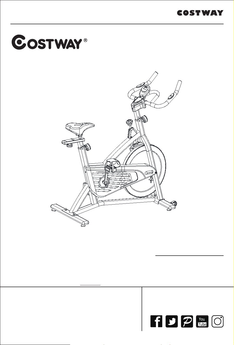
USER’S MANUAL
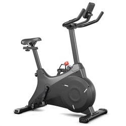
Spinning Bike
SP37421
Contact Us!
Do NOT return this item.
Contact our friendly customer service department for help first.
E-mail
US: cs.us@costway.com
UK: cs.uk@costway.com
Before You StartBefore You Start
Please read all instructions carefully.
Retain instructions for future reference.
Separate and count all parts and hardware.
Read through each step carefully and follow the proper order.
We recommend that, where possible, all items are assembled near to the
area in which they will be placed in use, to avoid moving the product
unnecessarily once assembled.
Always place the product on a flat, steady and stable surface.
Keep all small parts and packaging materials for this product away from
babies and children as they potentially pose a serious choking hazard.
www.costway.com
02

www.costway.com
Note the following precaution before assembling or operating the
machine.
1、Keep children and pets away from the Spinning Bike at all times.
DO NOT leave unattended children in the same room with the machine.
2、Handicapped or disabled persons should not use the Spinning Bike without the
presence of a qualified health professional or physician.
3、If the user experiences dizziness, nausea, chest pain, or any other abnormal
symptoms, STOP the workout at once. CONSULT A PHYSICIAN IMMEDIATELY.
4、Before beginning training, remove all within a radius of 2 meters from the
machine. DO NOT place any sharp objects around the Spinning Bike.
5、Position the Spinning Bike on a clear, level surface away from water and moisture.
Place mat under the unit to help keep the machine stable and to protect flooring.
6、Use the Spinning Bike only for its intended use as described in this manual. DO
NOT use any other accessories not recommended by the manufacturer.
7、Assemble the machine exactly as the descriptions in the instruction manual.
8、Check all bolts and other connections before using the machine for the first time
and ensure that the trainer is in the safe condition.
9、Hold a routine inspection of the equipment. Pay special attention to components
which are the most susceptible to wear off, i.e. connecting points and wheels. The
defective components should be replaced immediately. The safety level of this
equipment can only be maintained by doing so. Please don't use the Spinning Bike
until it is repaired well.
10、NEVER operate the Spinning Bike if it is not functioning properly.
11、This machine can be used for only one person’s training at a time.
12、Do not use abrasive cleaning articles to clean the machine.
Remove drops of sweat from the machine immediately after finishing training.
13、Always wear appropriate workout clothing when exercising.
Running or aerobic shoes are also required.
14、Before exercising, always do stretching first.
15、The power of the machine increases with increasing the speed, and the reverse.
The machine is equipped with adjustable knob, which can adjust the resistance.
03
www.costway.com
WARNING: BEFORE BEGINNING THIS OR ANY EXERCISE PROGRAM,
CONSULT YOUR PHYSICIAN F I R S T. THIS IS ESPECIALLY
IMPORTANT FOR INDIVIDUALS OVER THE AGE OF 35 OR PERSONS
WITH PRE-EXISTING HEALTH PROBLEMS. READ ALL INSTRUCTIONS
BEFORE USING THE SPINNING BIKE . OUR COMPANY ASSUMES NO
RESPONSIBILITY FOR PERSONAL INJURY OR PROPERTY DAMAGE
SUSTA I N E D BY OR THROUGH THE USE OF THIS PRODUCT
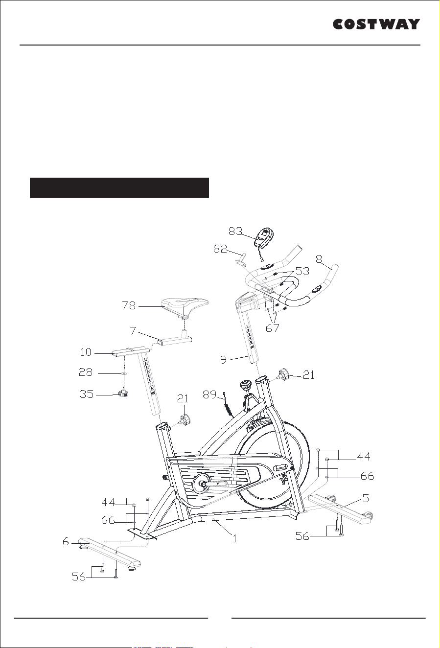
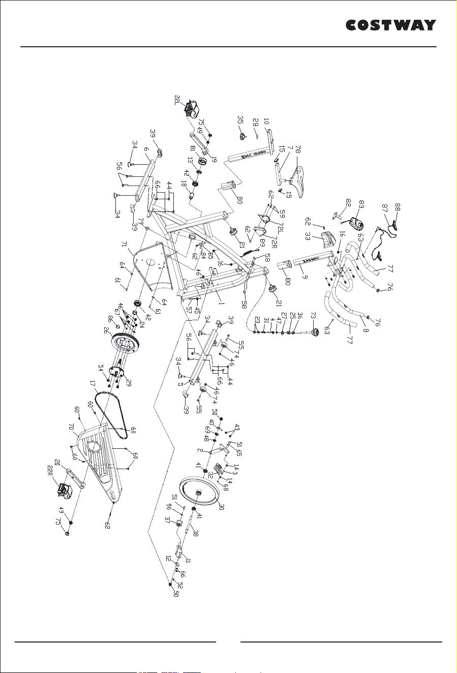
Exploded-View & Parts List:
04
www.costway.com
05

www.costway.com
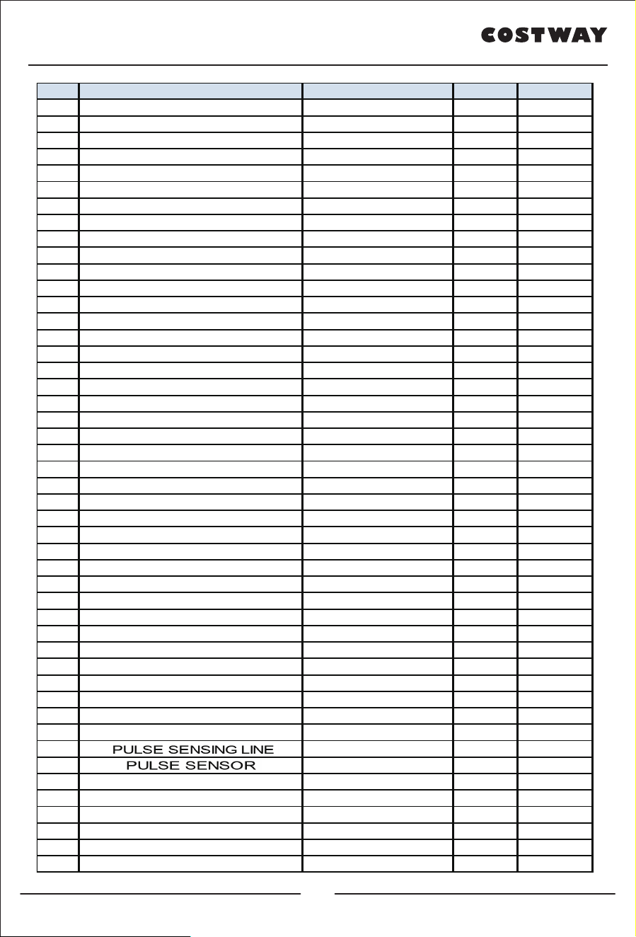
NO DESCRIPTION SPECIFICATION Q'TY UNIT
1 MAIN FRAME WELDMENT 1 PCS
2
MAGNET HOLDER
SUPPORTER
WELDMENT 1 PCS
3 MAGNET HOLDER WELDMENT 1 PCS
4 BRAKE POLE WELDMENT 1 PCS
5 FRONT STABILIZER WELDMENT 1 PCS
6 REAR STABILIZER WELDMENT 1 PCS
7 SEAT POST WELDMENT 1 PCS
8 HANDLE BAR WELDMENT 1 PCS
9 HANDLEBAR POST WELDMENT 1 PCS
10 VERTICAL SEAT POST WELDMENT 1 PCS
11 BELT WHEEL HOLDER WELDMENT 1 PCS
12 METAL PLATE δ2.5 2 PCS
13 FIXING NUT φ28*M20*1 1 PCS
14 CASING φ18*φ10*10 2 PCS
15 END CAP 40*20*1.5 2 PCS
16 PLASTIC PLUG φ14*14 3 PCS
17 BELT 5PK 1 PCS
18 LONG FIXING TUBE φ25*φ20.5*41.1 1 PCS
19 LEFT CRANK 170*27 1 PCS
20 RIGHT CRANK 170*27 1 PCS
21 SPRING ADJUSTMENT KNOB φ57*66 2 PCS
22 PEDAL JD-301 9/16" 1 SET
23 CASING PIPE 20.6*20.6*16 2 PCS
24 SHORT FIXING TUBE φ25*20.05*9 1 PCS
25 SPRING φ15.5*φ1.5X15 1 PCS
26 BELT PULLEY φ200*24 1 PCS
27 NUT 20*20*t8(M10) 2 PCS
28 FLAT WASHER Φ32*Φ8.2*2 1 PCS
29 AXIS φ20*168 1 PCS
30 FLYWHEEL φ463*65 13KG 1 PCS
31 SPRING Φ2.0*52 1 PCS
32 MAGNET 30*15*10 7 PCS
33 HANDLEBAR COVER 115*89*75 1 PCS
34 STOPPER φ38*43/(M8X25) 4 PCS
35 LOCKING KNOB PE+Q235/φ52*47 1 PCS
36 BRAKE TUBE PLUG 25*25*27 1 PCS
37 PRESS ROLLOR φ43*28 1 PCS
38 FLYWHEEL SHAFT φ16*φ12*156 1 PCS
39 END CAP 70*30*1.5 4 PCS
40 FIXING BOLT M6*57φ12 1 PCS
41 BEARING 6001ZZ 6001ZZ(C&U) 2 PCS
42 BEARING 6004ZZ 6004ZZ 2 PCS
43 NUT
M6
2 PCS
44 DOMED NUT M8 4 PCS
45 NUT M8 1 PCS
46 LOCK NUT M8 M8 7 PCS
47 LOCK NUT M10 M10 1 PCS
06
www.costway.com
NO DESCRIPTION SPECIFICATION Q'TY UNIT
48 FIXING NUT M12X1.25 1 PCS
49 FLANGE NUT
M10*1.25
2 PCS
50 FIXING NUT M12X1.25 2 PCS
51 BOLT M6*10 M6*10 3 PCS
52 BOLT M8*10 M8*10 1 PCS
53 BOLT M8*15 M8*15 4 PCS
54 BOLT M8*18 4 PCS
55 BOLT
M8*40
2 PCS
56 CARRIAGE BOLT M8*42 4 PCS
57 SCREW M8*45 1 PCS
58 SCREW
ST2.9*9.5
4 PCS
59 SCREW ST4.2*13 2 PCS
60 SCREW ST4.2*16 7 PCS
61 SCREW ST4.2*19 2 PCS
62 SCREW ST4.2X16 5 PCS
63 SCREW ST4.2X19 2 PCS
64 FLAT WASHER Φ5 5 2 PCS
65 FLAT WASHER Φ6 6 2 PCS
66 FLAT WASHER Φ8 8 6 PCS
67 SPRING WASHER 8 8 PCS
68 WASHER Φ10 1 PCS
69 FLAT WASHER Φ12 12 1 PCS
70 OUTER CHAIN COVER 743*283*75 1 PCS
71 INNER CHAIN COVER 462*276*15 1 PCS
72 BRAKE COVER 95.8*16.9*72.7 1 PCS
73 BRAKE KNOB M10*100 1 PCS
74 WHEEL φ50*23 2 PCS
75 CRANK END CAP φ23*7.5 2 PCS
76 END CAP φ25*1.5 2 PCS
77 FOAM GRIP φ23*φ29*465 2 PCS
78 SEAT DD-2681 1 PCS
79 CASING φ20*φ10.1*3 2 PCS
80 PLASTIC SLEEVE 50*25*1.5 60*30*1.5 2 PCS
81 CRANK COVER φ56*28 1 PCS
82 COMPUTER HOLDER 70*55MM 1 PCS
83 COMPUTER HS-6065 1 PCS
84 SENSOR SR-212 1 PCS
85 THE FIXED FRAME LTF8163 1 PCS
86 MAGNET c-02Z 1 PCS
87 PULSE SENSOR 700mm 1 PCS
88 PULSE SENSING LINE
φ25
2 PCS
89 SENSING LINE 850mm 1 PCS
90 FLAT WASHER Φ8 8 1 PCS
91 CROSSHEAD SPANNER S=13,14,15 1 PCS
92 INNER HEXAGON SPANNER 6# (86X35) 1 PCS
93 SPANNER S=10
、
13 1 PCS
94 WRENCH δ3 (151X43.5) 1 PCS
07
www.costway.com
1.Preparation:
A. Before assembling make sure that you will have enough space around the item.
B. Use the present tooling for assembling.
C. Before assembling please check whether all needed parts are available (at the
above of this instruction sheet you will find an explosion drawing with all single parts
(marked with numbers) which this item consists of.
2.ASSEMBLY INSTRUCTION:
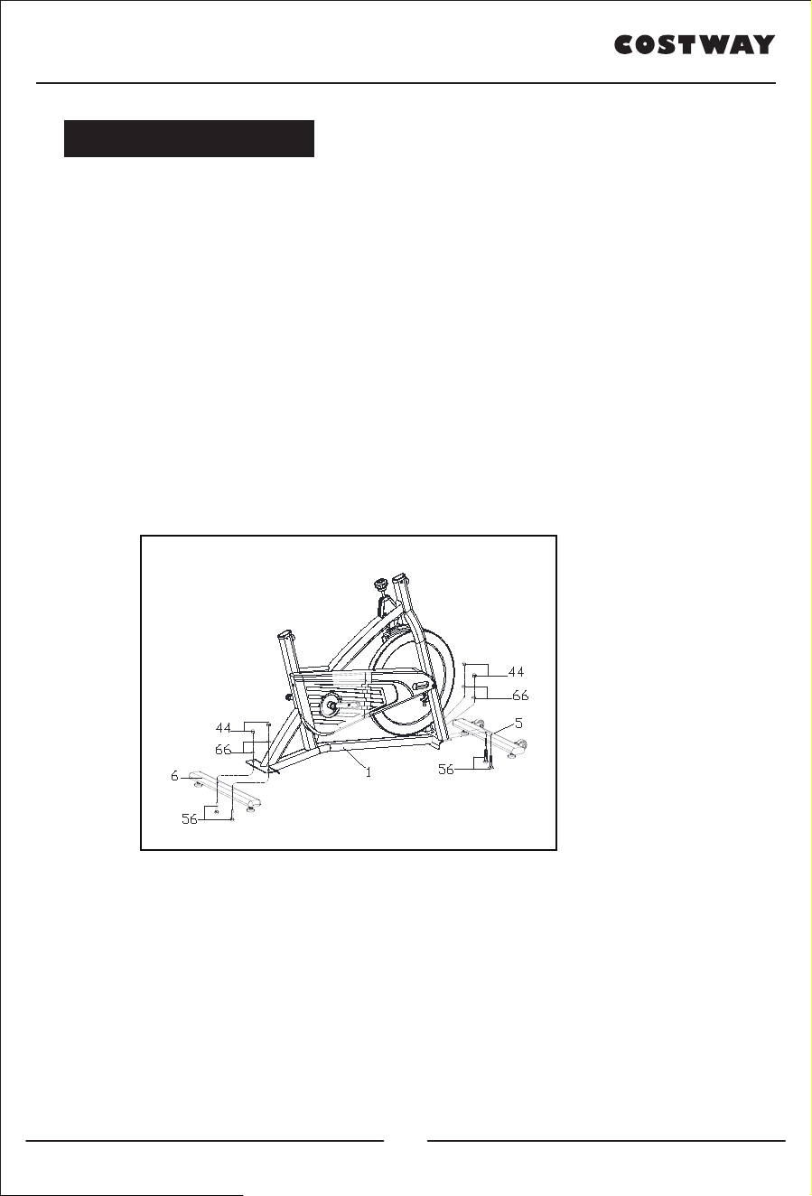
FIG.1:
Attach the Front Stabilizer (pt.5) to the Main Frame (pt.1) using two sets of Ø8 Flat
Washers (pt.66), M8 Domed Nut (pt.44) and M8*45 Carriage bolt (56). Attach the
Rear Stabilizer (pt.6) to the Main Frame (pt.1) using two sets of Ø8 Flat Washers
(pt.66), M8 Domed Nut (pt.44) and M8*45 Carriage bolt (56).
Assembly Instruction:
FIG.1
08
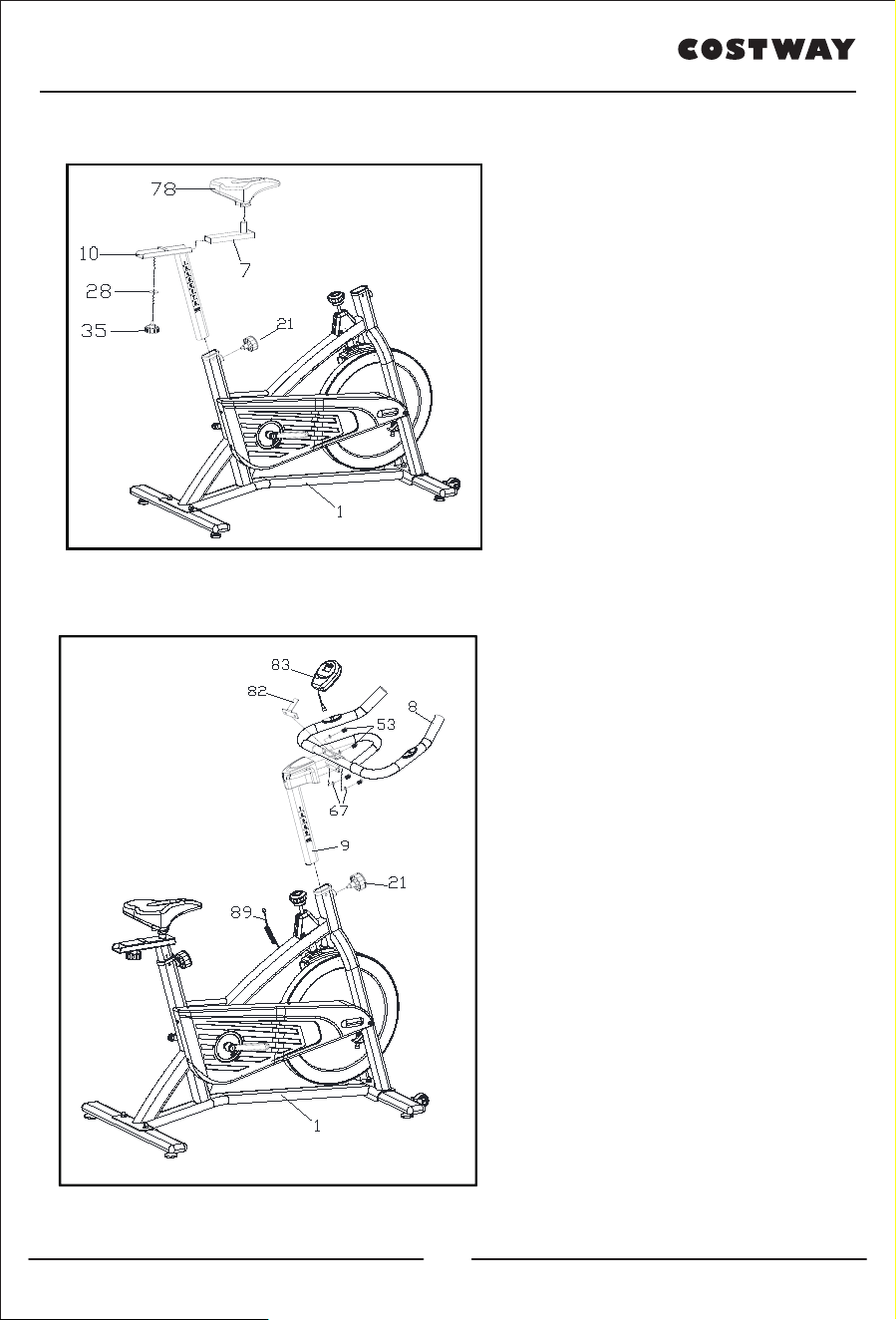
FIG.3:
Slide the Handlebar Post (pt.09) into
the handlebar post housing on the
main frame. You will have to slacken
the knurled section of the Spring
Adjustment Knob (pt.21) and pull the
knob back and then select and align
holes for the desired height. Release
the knob and retighten the knurled
portion.
Then fix the Handlebar (pt.08) and the
Computer Holder (pt.82) and
computer(pt.83) with two sets of Ø8
the Spring Washer (pt.67) and M8*15
the Bolt (pt.53).
ATTENTION: YOU
SHOULD FIX THE
HANDLEBAR TIGHTLY
FIG.3
www.costway.com
FIG.2:
Slide the Vertical Seat Post (pt.10)
into the seat post housing on the main
frame (pt.1). Then slide the Seat Post
(pt.7) into the Vertical Seat Post
(pt.10). You will have to slacken the
knurled section of the Spring
Adjustment Knob (pt.35) and Washers
(pt.28),then pull the knob back and
then select and align holes for the
desired height. Release the knob and
retighten the knurled portion.
Now fix the Seat (pt.78) to the Vertical
Seat Post (pt.7) as shown, and tighten
the bolts around the screws under the
seat.
FIG.2
09
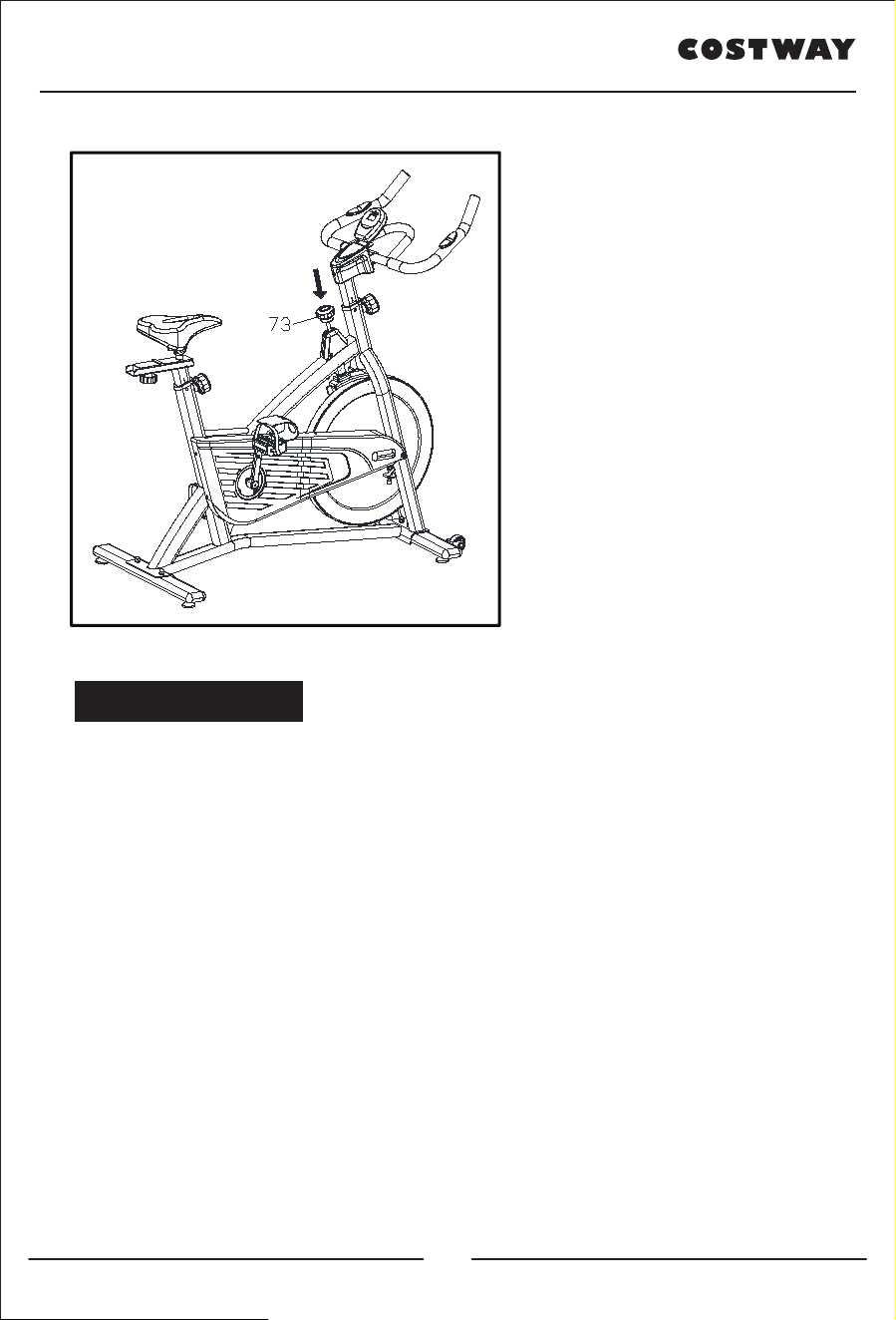
A.) Adjusting the Tension:
Increasing or decreasing the
tension allows you to add variety
to your workout sessions by
adjusting the resistance level of
the bike.
To increase tension and increase
resistance (requiring more
strength to pedal), turn the
Emergency Brake & Tension
Control Knob (#73) to the right.
To decrease tension and increase
resistance (requiring less strength
to pedal), turn the Emergency
Brake & Tension Control Knob
(#73) to the left.B.) Using the
Emergency Brake Function:
FIG.A
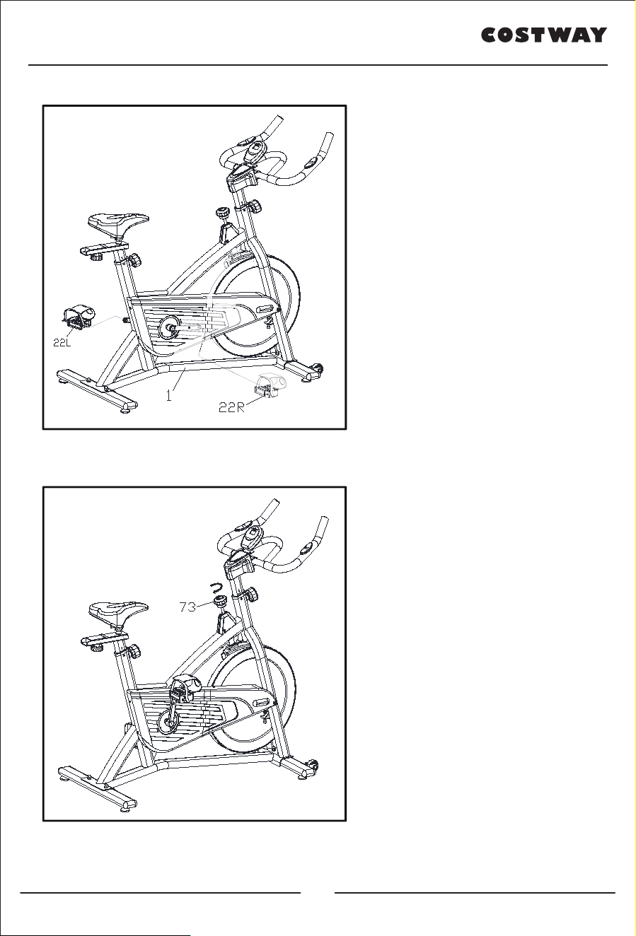
FIG.4:
The Pedals (pt.22 L & pt.22 R) are
marked "L" and "R" - Left and Right.
Connect them to their appropriate
crank arms. The right crank arm is
on the right- hand side of the cycle as
you sit on it.
Note that the Right pedal should be
threaded on clockwise and the Left
pedal anticlockwise.
FIG.4
www.costway.com
10
*To adjust the seat height, slacken the spring knob on the vertical
post stem on the main frame and pull back the knob. Position the
vertical seat post for the desired height so that holes are aligned,
then release the knob and retighten it.
*To move the seat forward in the direction of the handlebar or
backwards away from it, loosen the adjusting knob and washer and
pull the knob back. Slide horizontal seat post into desired position.
Align holes and then retighten the adjusting knob.
*To adjust the handlebar height, slacken the spring knob and pull
both knobs back.
Slide the handlebar post along the housing on the main frame to the
desired height and, with the holes aligned correctly, tighten the
spring adjusting knob.
The same knob that allows you to
adjust the tension of the bike also
functions as the Emergency
Brake. Use this safety feature in
any situation when you would
need to get off the bike and/or
stop the bike’s flywheel.
To use the Emergency Brake
function any situation you would
need it in, firmly press down
on the Emergency Brake & Brake
Control Knob (#73).
ADJUSTMENT
www.costway.com
11
www.costway.com
Using your SPINNING BIKE provides you with several benefits, it will improve
your physical fitness, tone muscle and in conjunction with calorie controlled diet
help you lose weight.
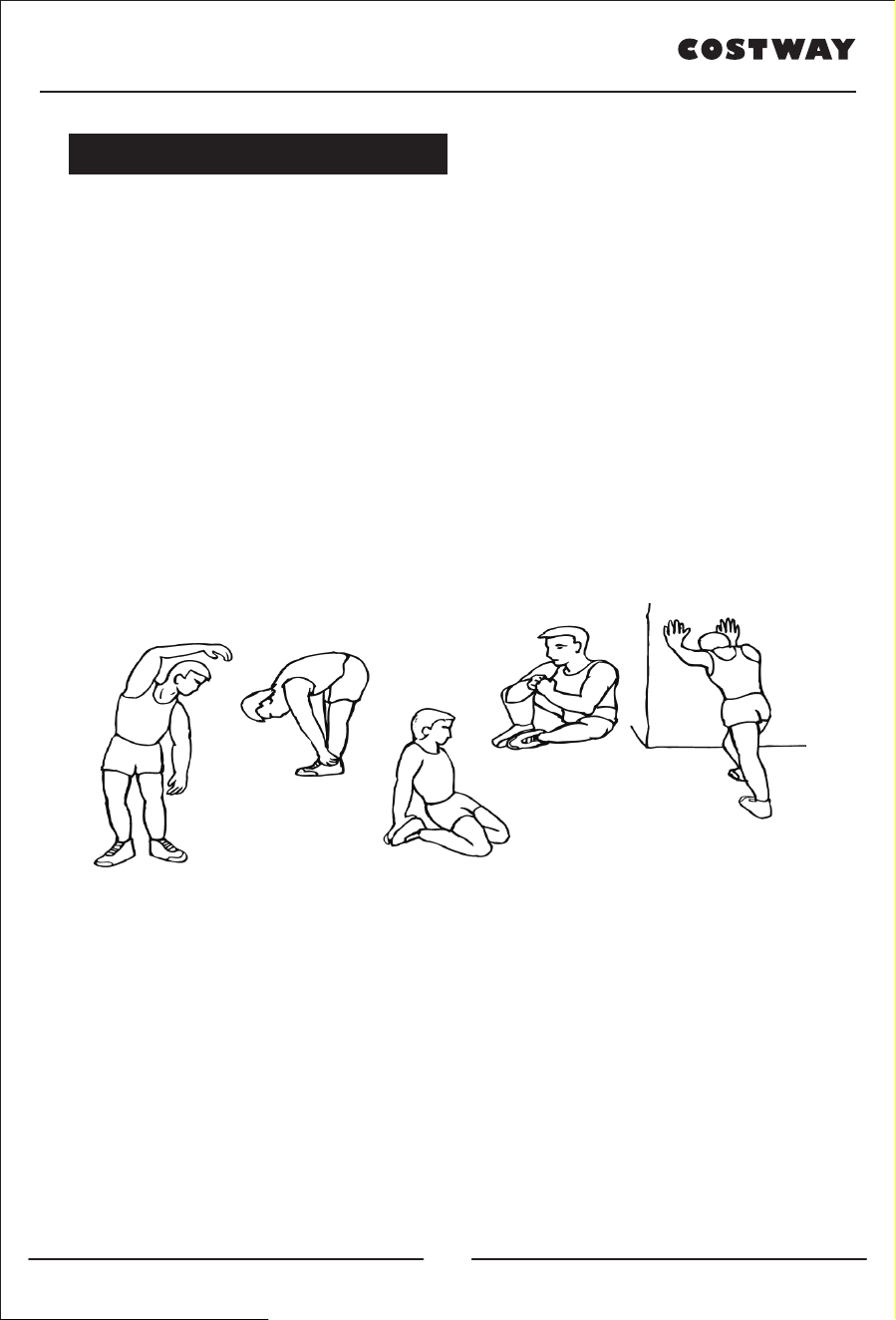
1.The Warm Up Phase
This stage helps get the blood flowing around the body and the muscles working
properly. It will also reduce the risk of cramp and muscle injury. It is advisable to do
a few stretching exercises as shown below. Each stretch should be held for
approximately 30 seconds, do not force or jerk your muscles into a stretch - if it
hurts, STOP.
2.The Exercise Phase
This is the stage where you put the effort in. After regular use , the muscles in your
legs will become Stronger. Work to your routine but it is very important to maintain
a steady tempo throughout. The rate of work should be sufficient to raise your heart
beat into the target zone shown on the graph below.
EXERCISE INSTRUCTIONS
SIDE BENDS
FORWARD BENDS
OUTER THIGH
INNER THIGH
CALF / ACHILLES
12

www.costway.com
This stage should last for a minimum of 12 minutes for most people.
This stage is to let your Cardio-vascular System and muscles wind down. This is a
repeat of the warm up exercise e.g. reduce your tempo, continue for approximately 5
minutes. The stretching exercises should now be repeated, again remembering not to
force or jerk your muscles into the stretch.
As you get fitter you may need to train longer and harder. It is advisable to train at
least three times a week, and if possible space your workouts evenly throughout the
week.
MUSCLE TONING
To tone muscle while on your SPINNING BIKE you will need to have the resistance
set quite high. This will put more strain on our leg muscles and may mean you cannot
train for as long as you would like. If you are also trying to improve your fitness you
need to alter your training program. You should train as normal during the warm up
and cool down phases, but towards the end of the exercise phase you should increase
resistance, making your legs work harden than normal. You may have to reduce your
speed to keep your heart rate in the target zone.
WEIGHT LOSS
The important factor here is the amount of effort you put in. The harder and longer
you work the more calories you will burn. Effectively this is the same as if you were
training to improve your fitness, the difference is the goal.
USE
The tension control knob allows you to alter the resistance of the pedals. A high
resistance makes it more difficult to pedal, a low resistance makes it easier. For the
best results set the tension while the bike is in use.
13
Welcome to visit our website and purchase our quality products!
We would like to extend our hear�elt thanks to
all of our customers for taking �me to assemble
this product and giving us valuable feedbacks.
With your inspiring rating, COSTWAY will be more consistent to offer you
EASY SHOPPING EXPERIENCE, GOOD PRODUCTS and EFFICIENT SERVICE!
US office: Fontana, California
UK office: Ipswich
www.costway.com
Reward Points
Exclusive Customer Service
Personalized Recommenda�ons
Permanent Shopping Cart
Order History
www.costway.com
14