
SMART MAGNETIC RESISTANCE
EXERCISE BIKE WITH DUMBBELL
HOLDER
SF-B123033
USER MANUAL
English, Pages 1~15 IMPORTANT! Please retain owner’s manual for maintenance and adjustment
instructions. Your satisfaction is very important to us, PLEASE DO NOT
RETURN UNTIL YOU HAVE CONTACTED US:
support@sunnyhealthfitness.com or 1-877-90SUNNY (877-907-8669).
Español, Páginas 16~30 IMPORTANTE! Por favor, conserve el manual del propietario para las
instrucciones de mantenimiento y ajuste. Su satisfacción es muy importante para
nosotros, POR FAVOR NO DEVUELVA EL PRODUCTO HASTA QUE SE
HAYA COMUNICADO CON NOSOTROS: support@sunnyhealthfitness.com o
1-877-90SUNNY (877-907-8669).

1
IMPORTANT SAFETY INFORMATION
We thank you for choosing our product. To ensure your safety and health, please use this
equipment correctly. It is important to read this entire manual before assembling and using the
equipment. Safe and effective use can only be achieved if the equipment is assembled,
maintained and used properly. It is your responsibility to ensure that all users of the equipment
are informed of all warnings and precautions.
1. Before starting any exercise program, you should consult your physician to determine if you
have any medical or physical conditions that could put your health and safety at risk, or
prevent you from using the equipment properly. Your physician’s advice is essential if you are
taking medication that affects your heart rate, blood pressure or cholesterol level.
2. Be aware of your body’s signals. Incorrect or excessive exercise can damage your health.
Stop exercising if you experience any of the following symptoms: pain, tightness in your chest,
irregular heartbeat, shortness of breath, lightheadedness, dizziness or feelings of nausea. If
you do experience any of these conditions, you should consult your physician before
continuing with your exercise program.
3. Keep children and pets away from the equipment. The equipment is designed for adult use
only.
4. Use the equipment on a solid, flat level surface with a protective cover for your floor or carpet.
To ensure safety, the equipment should have at least 2 feet (60 cm) of free space all around it.
5. Ensure that all nuts and bolts are securely tightened before using the equipment. The safety
of the equipment can only be maintained if it is regularly examined for damage and/or wear
and tear.
6. Always use the equipment as indicated. If you find any defective components while
assembling or checking the equipment, or if you hear any unusual noises coming from the
equipment during exercise, discontinue use of the equipment immediately and do not use until
the problem has been rectified.
7. Wear suitable clothing while using the equipment. Avoid wearing loose clothing that may
become entangled in the equipment.
8. Do not place fingers or objects into the moving parts of the equipment.
9. The maximum weight capacity of this unit is 300 lbs (135 kgs).
10. The equipment is not suitable for therapeutic use.
11. To avoid bodily injury and/or damage to the product or property, proper lifting and moving is
required.
12. Your product is intended for use in cool and dry conditions. You should avoid storage in
extreme cold, hot or damp areas as this may lead to corrosion and other related problems.
13. This equipment is designed for indoor and home use only. It is not intended for commercial
use!
2
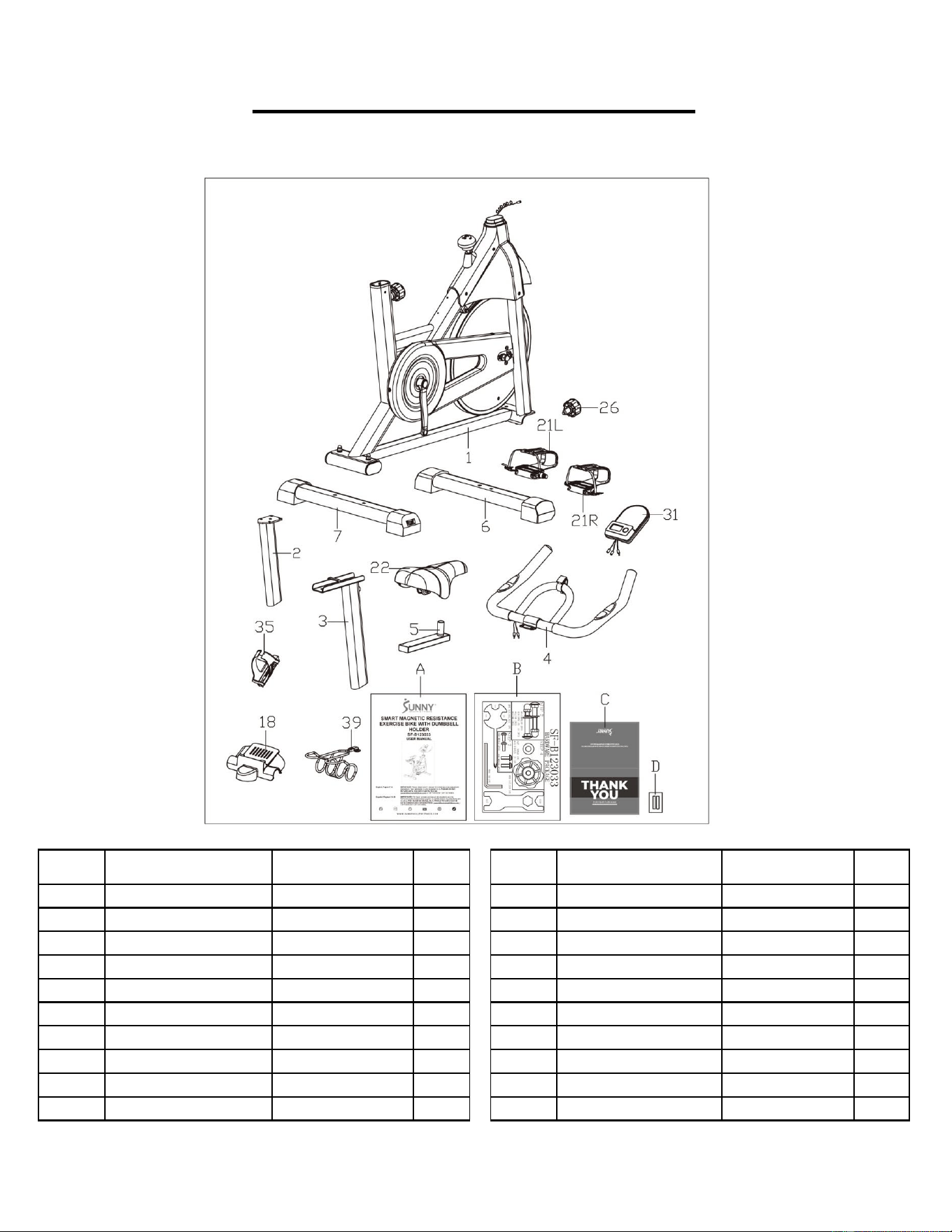
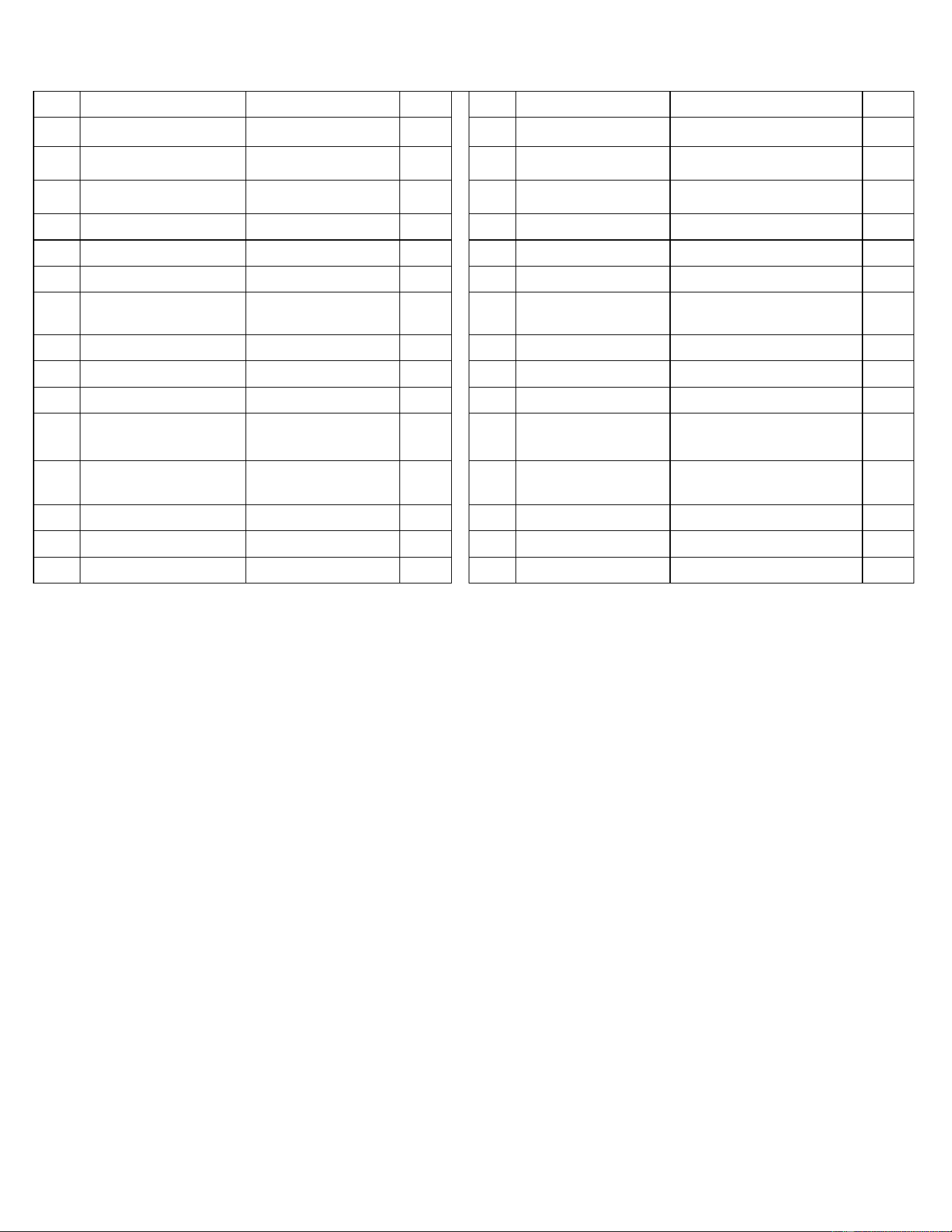
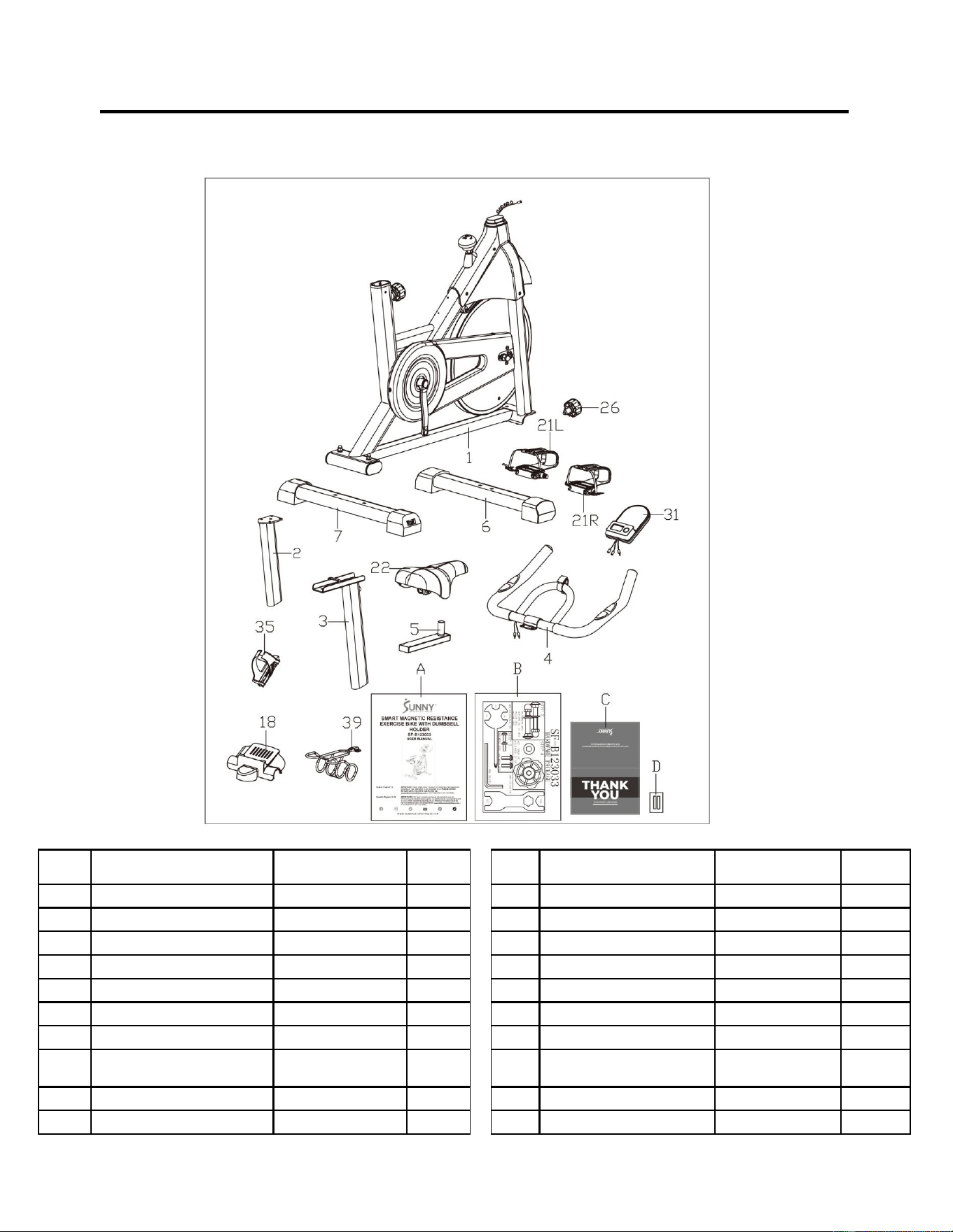
PRE-ASSEMBLY CHECK LIST
Before you start to assemble, please make sure all parts are included.
No.
Description
Spec.
Qty.
No.
Description
Spec.
Qty.
1
Main Frame
1
22
Seat
KX8022
1
2
Handlebar Post
1
26
Adjustment Knob
M16X1.5X22
1
3
Seat Post
1
31
Meter
BJHT-087
1
4
Handlebar
1
35
Bottle Holder
1
5
Seat Slider
1
39
Dumbbell Rack
1
6
Front Stabilizer
80X40X1.2X460
1
A
Manual
1
7
Rear Stabilizer
80X40X1.2X500
1
B
Hardware Package
1
18
Handlebar Cover
1
C
Thank You Card
1
21L
Left Pedal
9/16”X20
1
D
Battery
AAA
2
21R
Right Pedal
9/16”X20
1
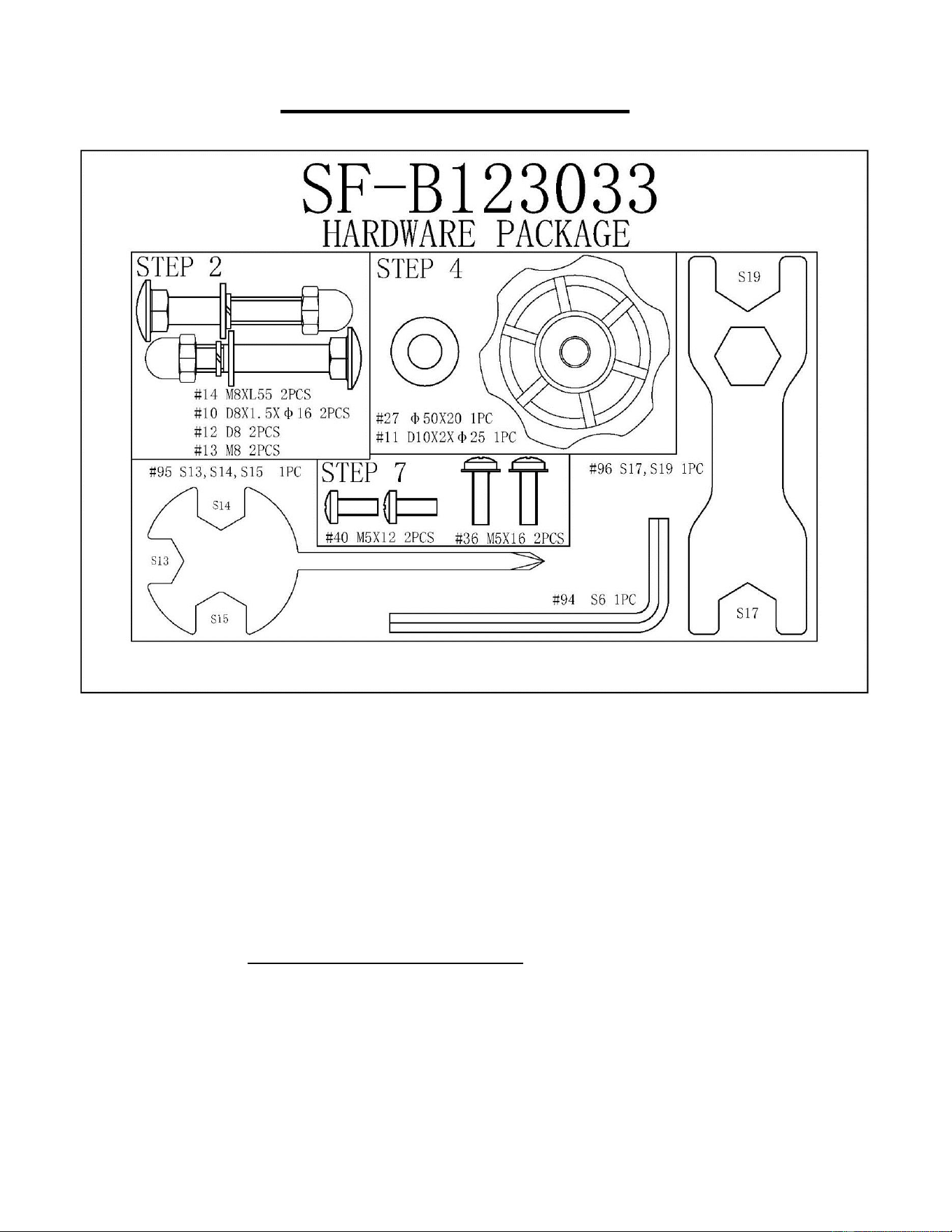
3
HARDWARE PACKAGE
Ordering Replacement Parts (U.S. and Canadian Customers only)
Please provide the following information in order for us to accurately identify the part(s) needed:
✓ The model number (found on cover of manual)
✓ The product name (found on cover of manual)
✓ The part number found on the “EXPLODED DIAGRAM” (pages 31~32) and “PARTS LIST”
(pages 14~15)
Please contact us at [email protected] or 1-877-90SUNNY (877-907-8669).
4
ASSEMBLY INSTRUCTIONS
We value your experience using Sunny Health and Fitness products. For assistance with parts or
troubleshooting, please contact us at suppo[email protected] or 1-877-90SUNNY (877-907-
8669).
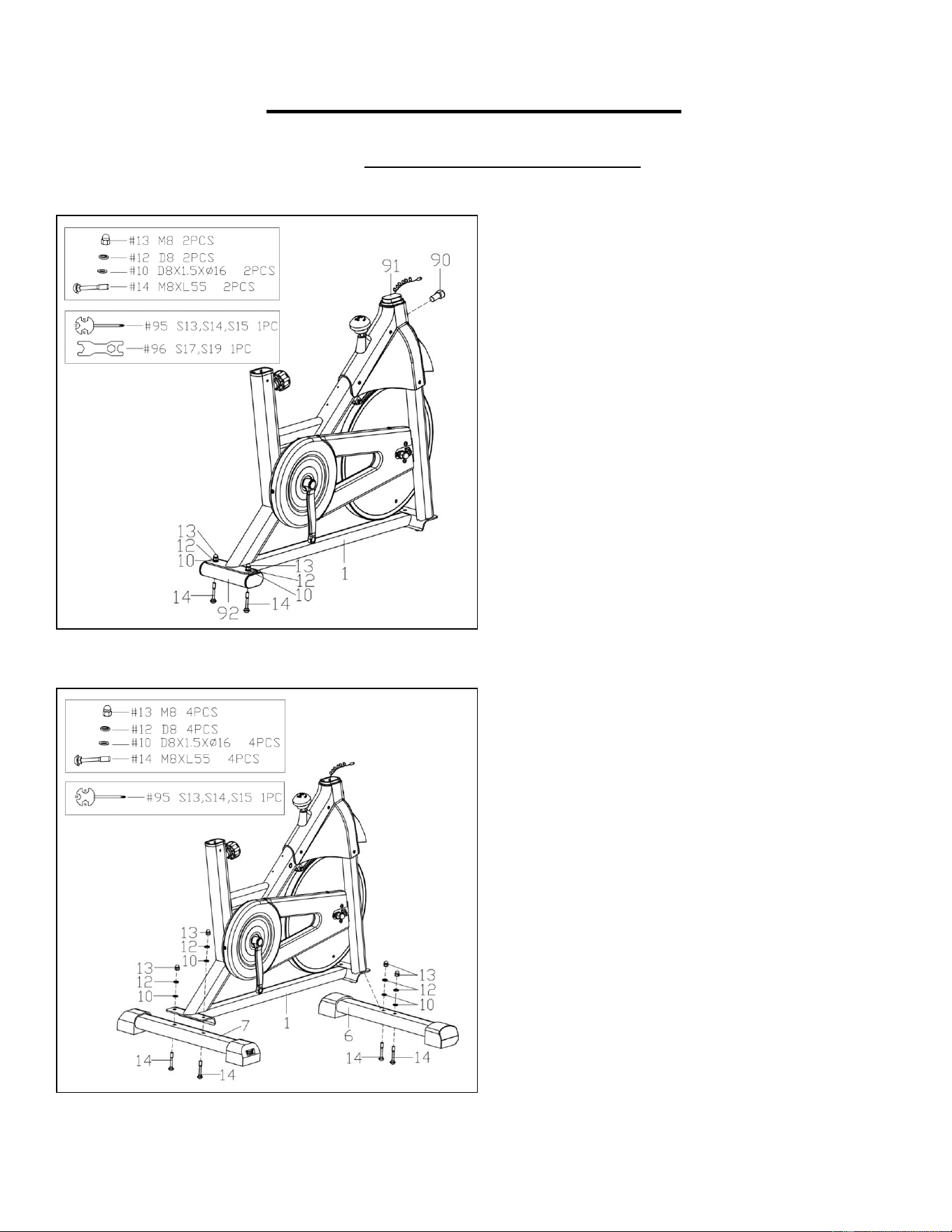
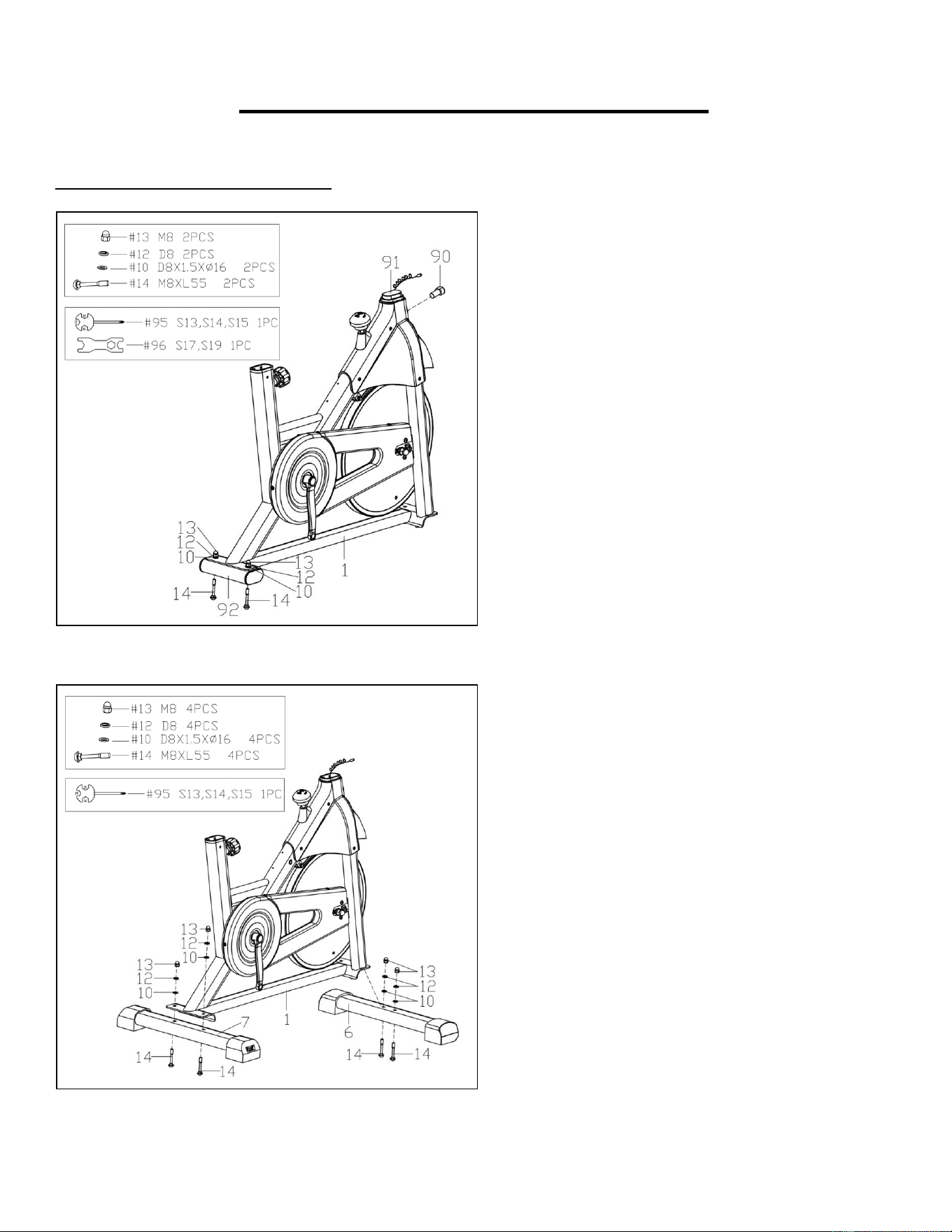
STEP 1:
Remove 2 Carriage Bolts (No. 14), 2 Flat
Washers (No. 10), 2 Cap Nuts (No. 13) and
2 Spring Washers (No. 12) from Shipping
Tube 2 (No. 92) using Spanner (No. 95).
Remove the Screw (No. 90) using Spanner
(No. 96) and take out the Shipping Tube 1
(No. 91) from Main Frame (No. 1).
NOTE: You may save these parts: Shipping
Tube 2 (No. 92) and Shipping Tube 1 (No.
91) for future packaging and transportation of
bike.
STEP 2:
Attach the Rear Stabilizer (No. 7) to the Main
Frame (No. 1) using 2 Carriage Bolts (No.
14), 2 Flat Washers (No. 10), 2 Cap Nuts
(No. 13) and 2 Spring Washers (No. 12) that
were just removed on STEP 1. Tighten and
secure with Spanner (No. 95).
Attach the Front Stabilizer (No. 6) to the
Main Frame (No. 1) using 2 Carriage Bolts
(No. 14), 2 Flat Washers (No. 10), 2 Cap
Nuts (No. 13) and 2 Spring Washers (No.
12). Tighten and secure with Spanner (No.
95).
5
We value your experience using Sunny Health and Fitness products. For assistance with parts or
troubleshooting, please contact us at suppo[email protected] or 1-877-90SUNNY (877-907-
8669).
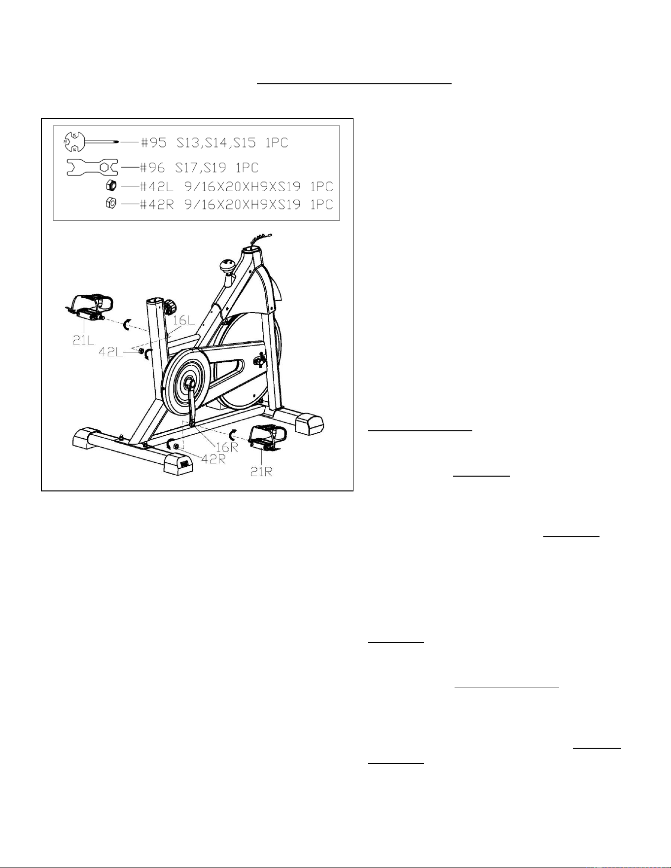
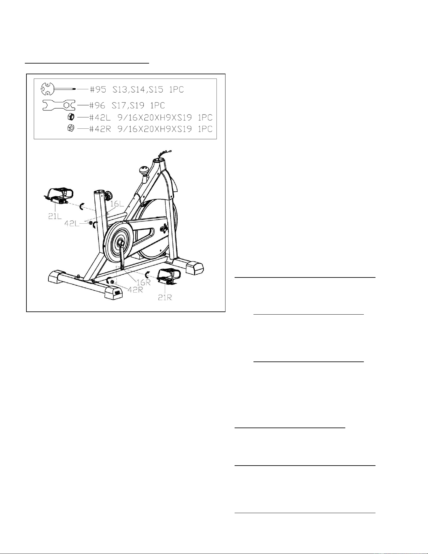
STEP 3:
IMPORTANT! Read instructions carefully,
failure to do so may cause permanent
damage to your bike.
Remove the Left & Right Nylon Nuts (No.
42L & No. 42R) located on the Left & Right
Pedals (No. 21L & No. 21R) with Spanner
(No. 96) and Spanner (No. 95). The Right
Nylon Nut (No. 42R) is WHITE on the
inside. The Left Nylon Nut (No. 42L) is
BLUE on the inside. Left Pedal (No. 21L) is
marked “L” on it, Right Pedal (No. 21R) is
marked “R” on it.
Align the Left Pedal (No. 21L) with the Left
Crank (No. 16L) at a 90° angle. Turn the
pedal bolt on the Left Pedal (No. 21L)
counter-clockwise as tightly as you can with
your hand. Then, use Spanner (No. 95) to
tighten and secure. Turn the Left Nylon
Nut (No. 42L) clockwise as tightly as you
can with your hand. Use Spanner (No. 95)
to hold the pedal bolt on the Left Pedal
(No. 21L) and use Spanner (No. 96) to turn
the Left Nylon Nut (No. 42L) clockwise at
the same time, until it is tightened onto the
Left Crank (No. 16L).
Align the Right Pedal (No. 21R) with the
Right Crank (No. 16R) at a 90° angle. Turn
the pedal bolt on Right Pedal (No. 21R)
clockwise as tightly as you can with your
hand. Then, use Spanner (No. 95) to
tighten and secure. Turn the Right Nylon
Nut (No. 42R) counter-clockwise as tightly
as you can with your hand. Use Spanner
(No. 95) to hold the pedal bolt on the Right
Pedal (No. 21R) and use Spanner (No. 96)
to turn Right Nylon Nut (No. 42R) counter-
clockwise at the same time, until it is
tightened onto the Right Crank (No. 16R).
6
We value your experience using Sunny Health and Fitness products. For assistance with parts or
troubleshooting, please contact us at suppo[email protected] or 1-877-90SUNNY (877-907-
8669).
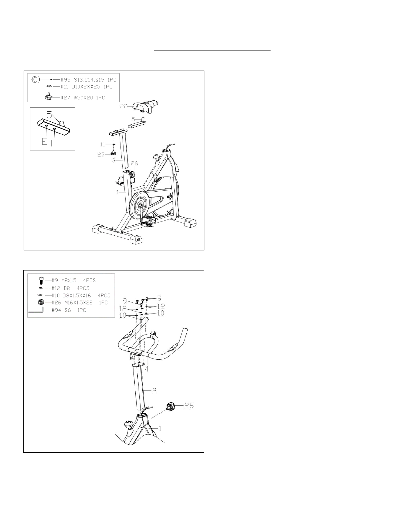
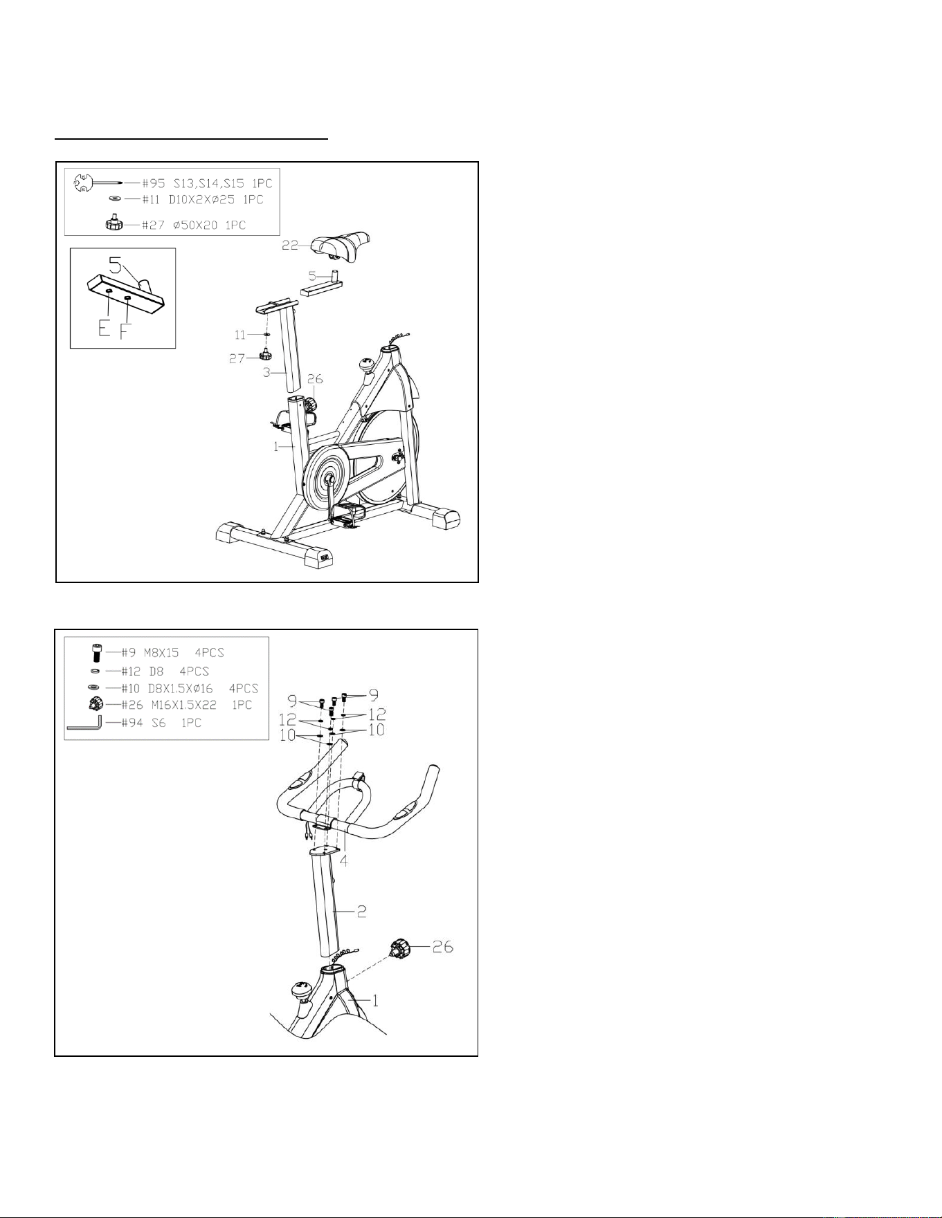
STEP 4:
Loosen and pull out the Adjustment Knob
(No. 26). Insert the Seat Post (No. 3) into the
sleeve located on the Main Frame (No. 1),
then lock with the Adjustment Knob (No.
26).
Insert the Seat Slider (No. 5) to the Seat
Post (No. 3), and lock with Adjustment
Knob (No. 27) and Flat Washer (No. 11)
after adjusting to Hole E or F on the Seat
Slider (No. 5).
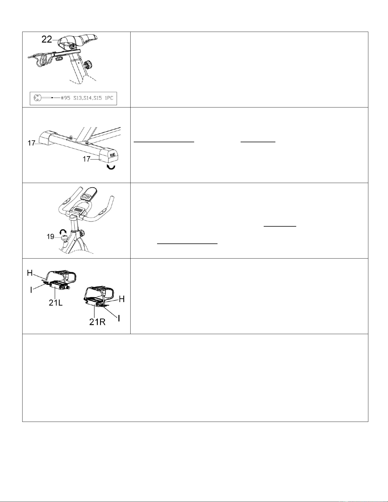
Attach the Seat (No. 22) to the Seat Slider
(No. 5). Tighten and secure with Spanner
(No. 95).
NOTE: Make sure the Seat (No. 22) is lock
tightly on the Seat Slider (No. 5) before
exercise.
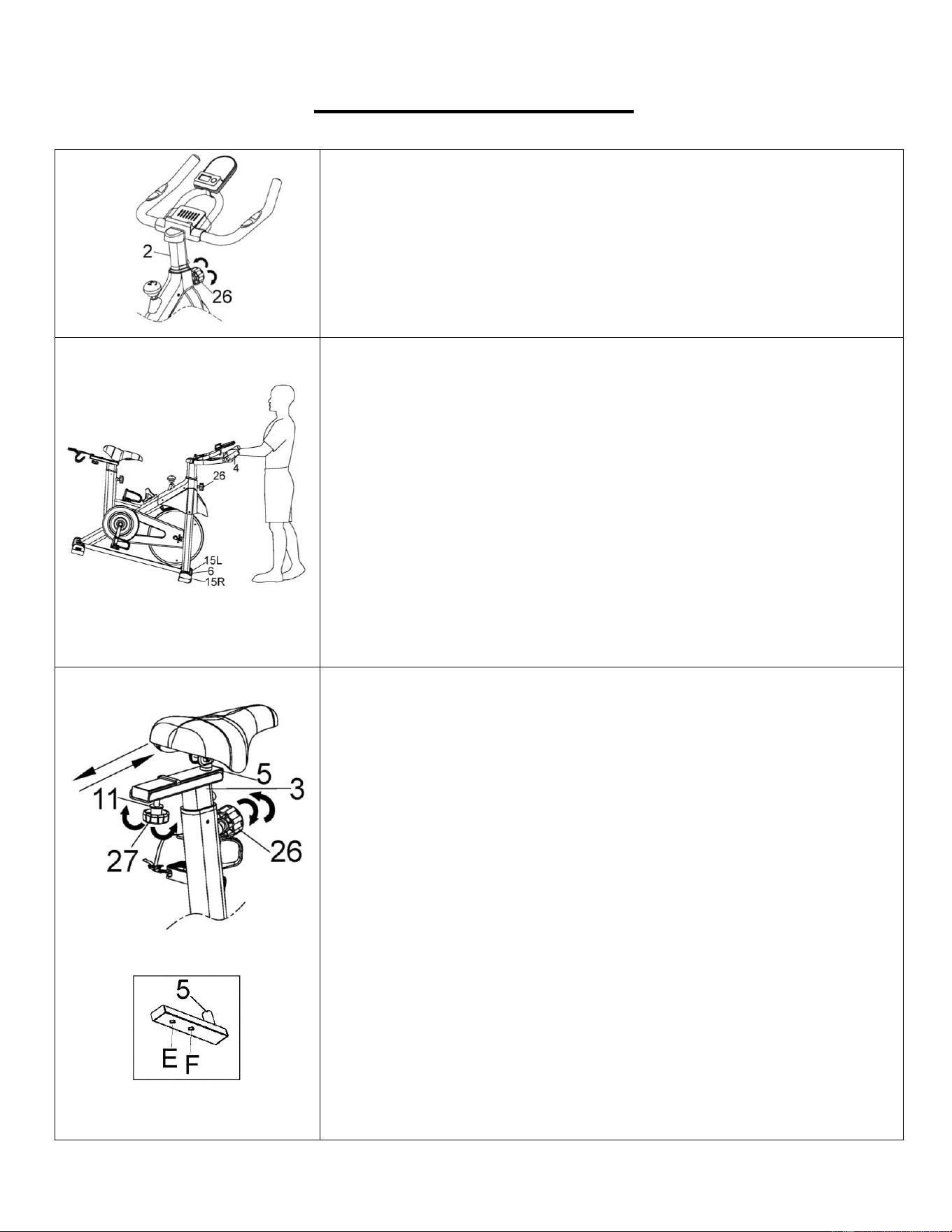
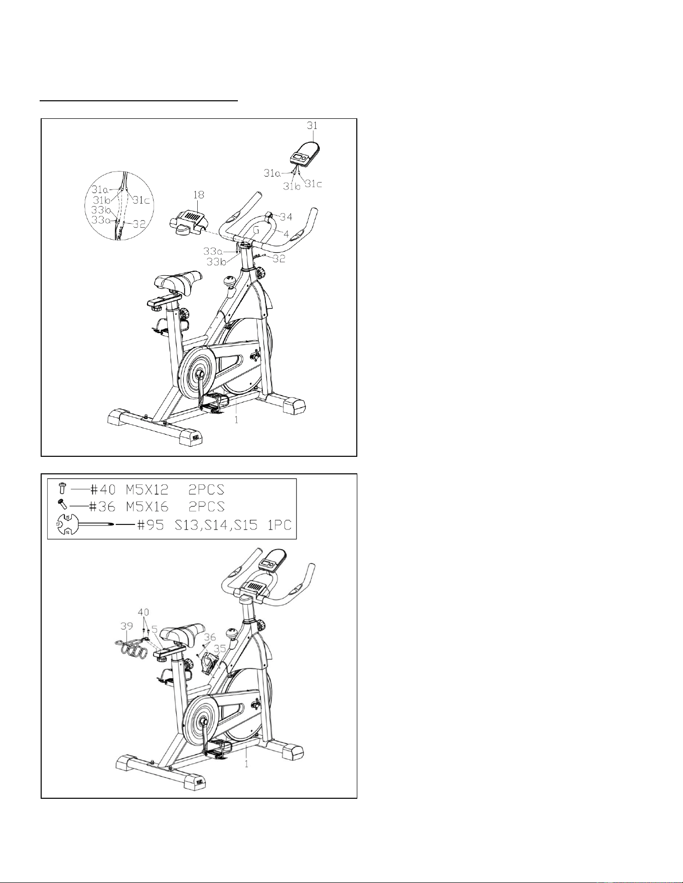
STEP 5
Insert the Handlebar Post (No. 2) to the
sleeve on the Main Frame (No. 1), then lock
with the Adjustment Knob (No. 26).
Remove 4 Screws (No. 9), 4 Spring
Washers (No. 12) and 4 Flat Washers (No.
10) from the Handlebar Post (No. 2) using
Allen Wrench (No. 94).
Attach the Handlebar (No. 4) to the
Handlebar Post (No. 2) using 4 Screws (No.
9), 4 Spring Washers (No. 12) and 4 Flat
Washers (No. 10) that were just removed.
Tighten and secure with Allen Wrench (No.
94).
7
We value your experience using Sunny Health and Fitness products. For assistance with parts or
troubleshooting, please contact us at suppo[email protected] or 1-877-90SUNNY (877-907-
8669).
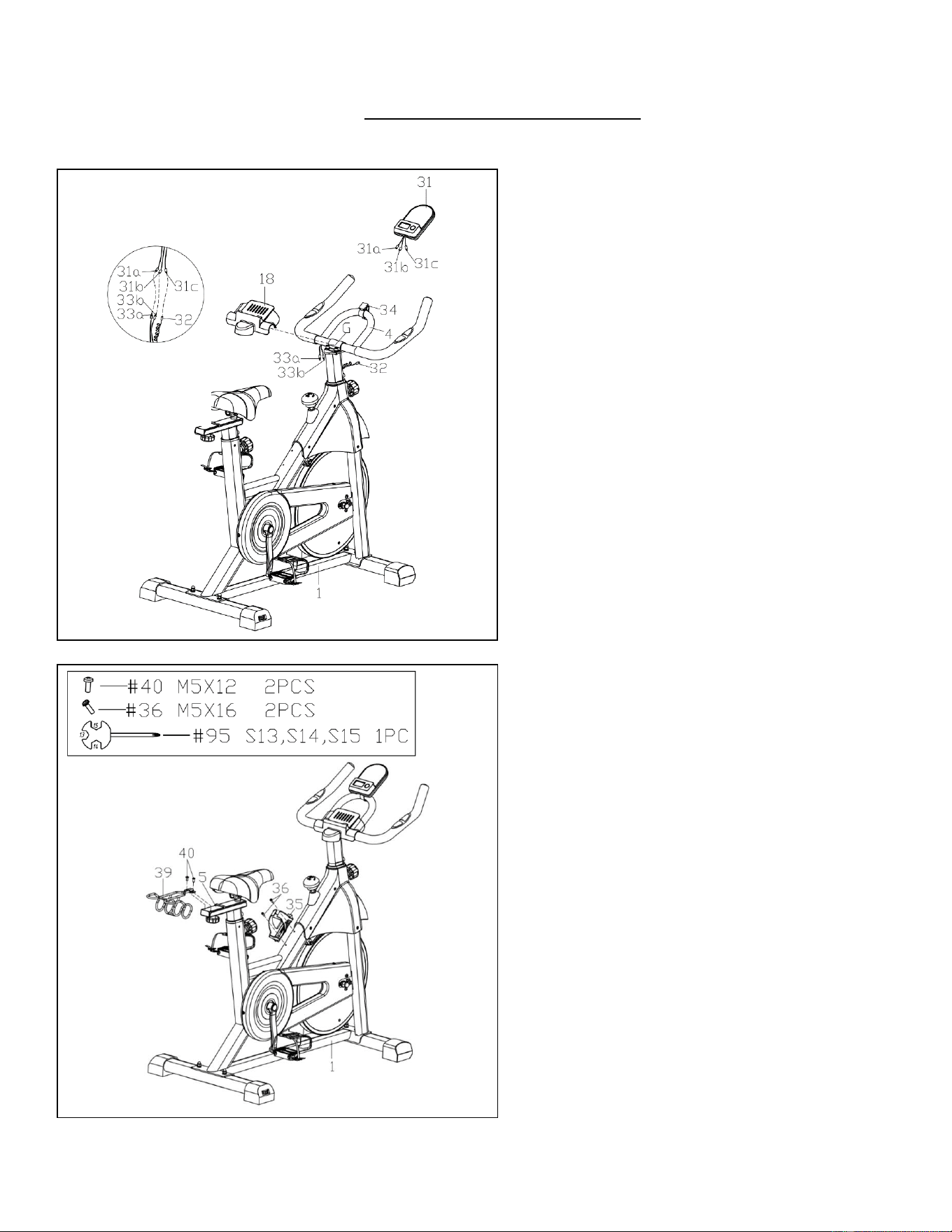
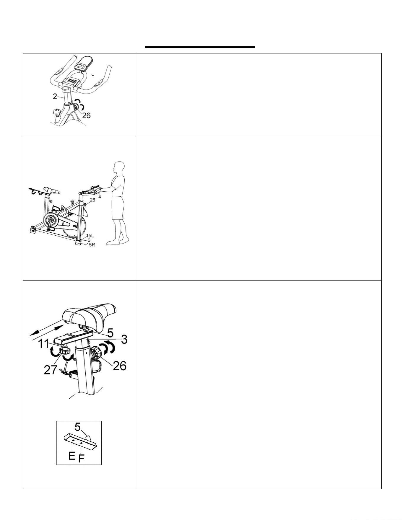
STEP 6:
Insert the Meter (No. 31) to the Meter
Bracket (No. 34), then connect Sensor
Wire (No. 32) and Meter Wire C (No.
31c), connect Pulse Wire A (No. 33a) with
Meter Wire A (No. 31a) and connect
Pulse Wire B (No. 33b) with Meter Wire B
(No. 31b).
Attach the Handlebar Cover (No. 18) to
the position G.
STEP 7:
Attach the Bottle Holder (No. 35) to the
Main Frame (No. 1) with 2 Screws with
Washer (No. 36) using Spanner (No. 95).
Attach the Dumbbell Rack (No. 39) to the
Seat Slider (No. 5) with 2 Screws (No.
40). Tighten and secure with Spanner (No.
95).
The assembly is complete!
8
ADJUSTMENT GUIDE
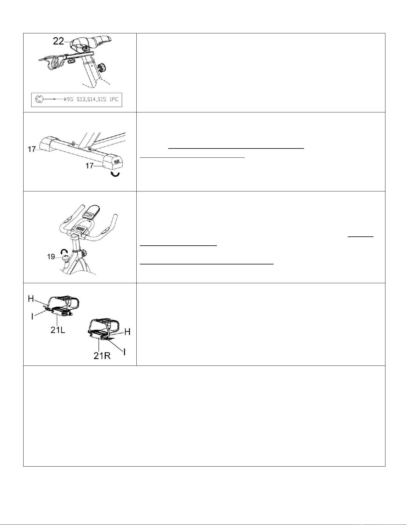
ADJUSTING THE HANDLEBAR:
It is important that the handlebar and seat are both set to the correct
height of your body. To adjust the handlebar height, loosen and pull
the Adjustment Knob (No. 26) outward, then slide the Handlebar
Post (No. 2) up or down to the desired height. Once adjusted, re-
insert and tighten the Adjustment Knob (No. 26) to secure the
Handlebar Post (No. 2) in place.
TRANSPORTING THE BIKE:
To move the bike, first ensure that the Handlebar (No. 4) is properly
secured. If the Handlebar (No. 4) is loose, tighten the Adjustment
Knob (No. 26) to secure it. Next, stand at the front of the bike so
that you’re directly in front of the Handlebar (No. 4). Firmly grasp
and hold each side of the Handlebar (No. 4), place one foot on the
Front Stabilizer (No. 6) and tilt the bike towards you until the
wheels on the Left & Right Front End Caps (No. 15L & No. 15R)
touch the ground. With the wheels on the ground, you can transport
the bike to the desired location with ease.
NOTE: When moving the bike, always use caution as unexpected
impact, such as dropping the bike, may cause injury and affect the
bike’s performance.
ADJUSTING THE SEAT
The seat of this bike is fully adjustable as it moves Up, Down, Fore
(forward), Aft (backward).
To adjust the height of the Seat Post (No. 3), loosen and pull the
Adjustment Knob (No. 26) outward, then raise or lower the seat to
the desired height. Once adjusted, re-insert and tighten the
Adjustment Knob (No. 26) to secure the Seat Post (No. 3) in
place.
To adjust the seat back and forth, loosen Adjustment Knob (No.
27), then move the Seat Slider (No. 5) to the desired location. Once
positioned, re-insert and tighten the Adjustment Knob (No. 27) to
secure the Seat Slider (No. 5) tube in place. You could change the
hole position of Adjustment Knob (No. 27) to increase the
adjustment range. For changing the hole position, please remove
the Adjustment Knob (No. 27) and Flat Washer (No. 11), then
adjust the Seat Slider (No. 5) to the desired hole (E or F). Once
adjusted, re-tighten the Seat Slider (No. 5) with the Adjustment
Knob (No. 27) and Flat Washer (No. 11) that were just removed.
9
TIGHTENING THE SEAT
Tighten the Seat (No. 22) by using the Spanner (No. 95) if the Seat
(No. 22) is loose.
ADJUSTING THE BALANCE
If the bike is not leveled, adjust the Rear End Caps (No. 17). Turn
counter-clockwise to raise, turn clockwise to lower.
ADJUSTING THE RESISTANCE
Adjust the resistance of the bike using the Tension Control Knob
(No. 19). Increase the level of resistance by turning Tension
Control Knob (No. 19) to the RIGHT (clockwise), decrease the level
of resistance by turning the Tension Control Knob (No. 19) to the
LEFT (counter-clockwise). Push down on the Tension Control
Knob (No. 19) for emergency brake.
PEDAL STRAP ADJUSTMENT
Place the ball of each foot in the toe clips so the front of your shoe
fits snugly in the toe clip cage (I). Rotate one foot to within arm’s
reach and pull the strap (H) until the top clip cage(I) fits your shoe
snugly. Insert the strap back into the hoop of the toe clip. Repeat
this for the other foot.
DISMOUNTING
For your safety, it is recommended that you never attempt to dismount or remove your feet from the
pedals until both the flywheel and pedals/cranks have come to a complete stop. Failure to follow this
recommendation may lead to loss of control and/or serious injury.
Here are a few examples of how to safely dismount the bike:
1. Reduce the pedal speed until the pedals/cranks come to a complete stop.
2. Increase the resistance until the pedals/cranks come to a complete stop.
3. Push and hold the tension control knob down until the pedals/cranks come to a complete stop.

10
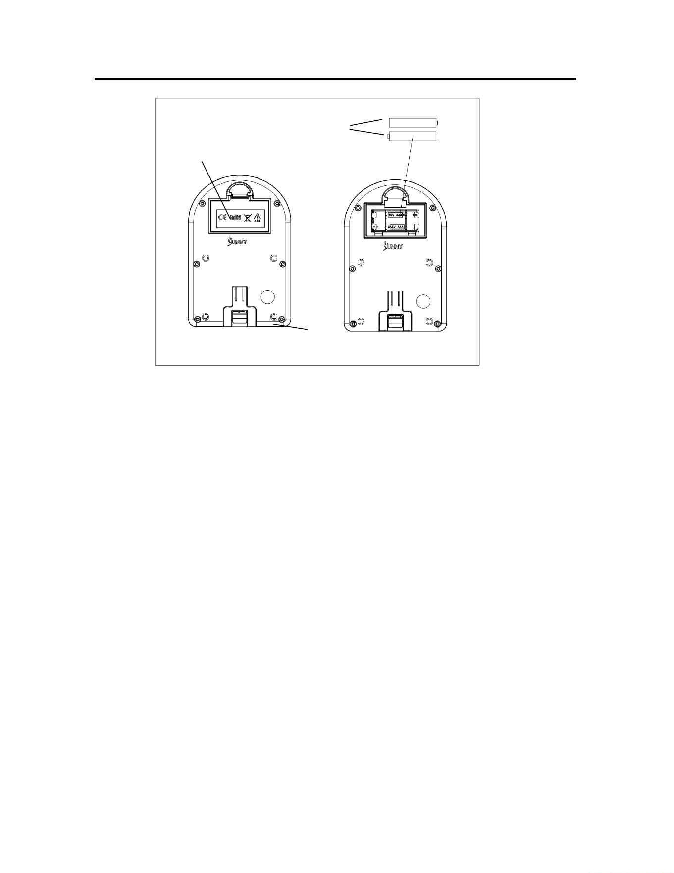
BATTERY INSTALLATION & REPLACEMENT
BATTERY INSTALLATION
1. Take out 2 AAA batteries from the meter box.
2. Press the buckle of battery cover on the Meter (No. 31), then remove battery cover.
3. Install 2 AAA batteries into the battery case on the back of the Meter (No. 31). Pay attention
to the battery + and – poles before installing.
4. Press the buckle of battery cover, then put the battery cover back to the back of the Meter
(No. 31).
The installation is complete!
BATTERY REPLACEMENT
1. Press the buckle of battery cover on the back of the Meter (No. 31), then remove battery
cover.
2. Remove the 2 old AAA batteries in the battery case and install 2 new AAA batteries into the
battery case on the back of the Meter (No. 31). Pay attention to the battery + and – poles
before installing.
3. Press the buckle of battery cover, then put the battery cover back to the back of the Meter
(No. 31).
The replacement is complete!
BATTERY DISPOSAL
Dispose the batteries according to the local laws and regulations of your region. Some batteries
may be recycled. When disposing or recycling, do not mix battery types.
Battery Cover
Battery
31
11
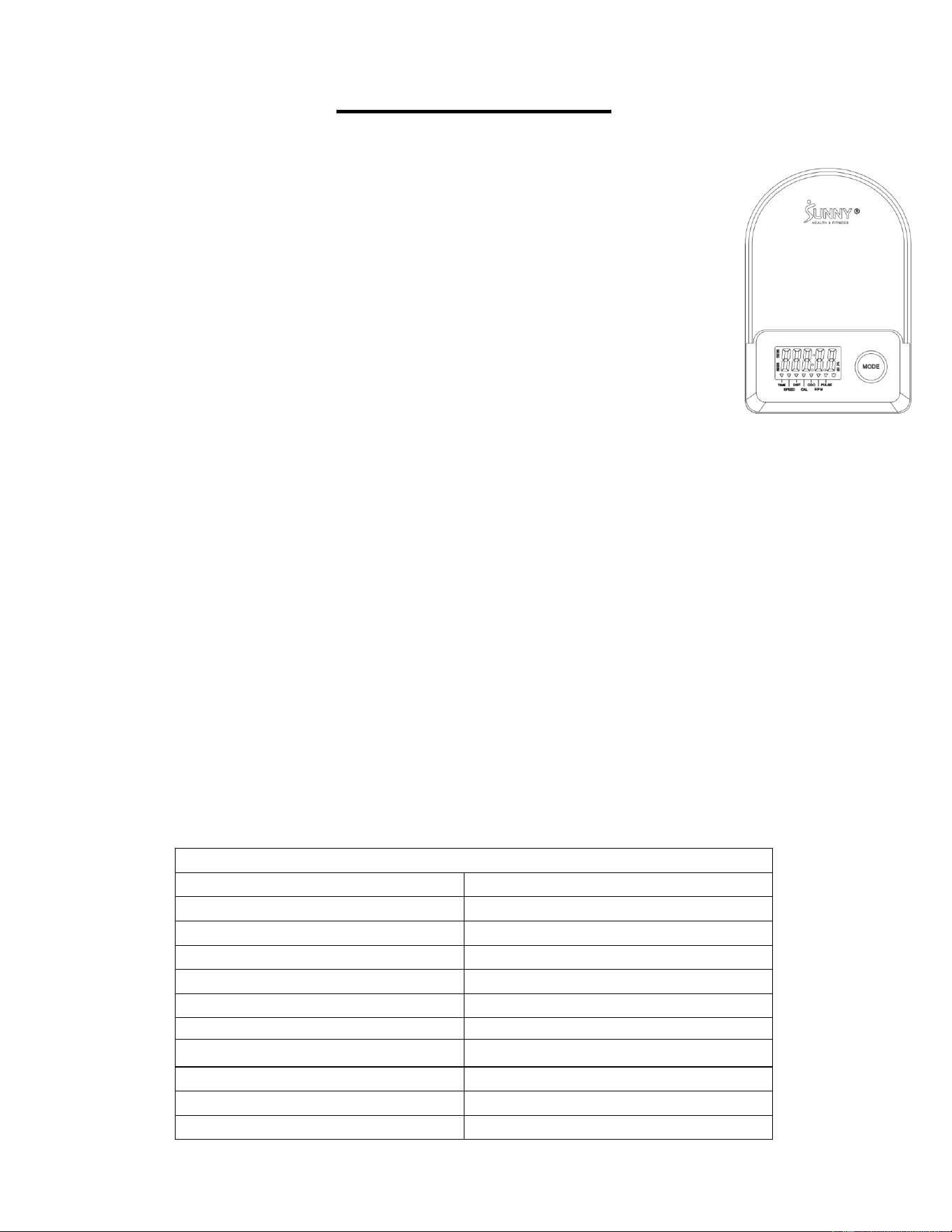
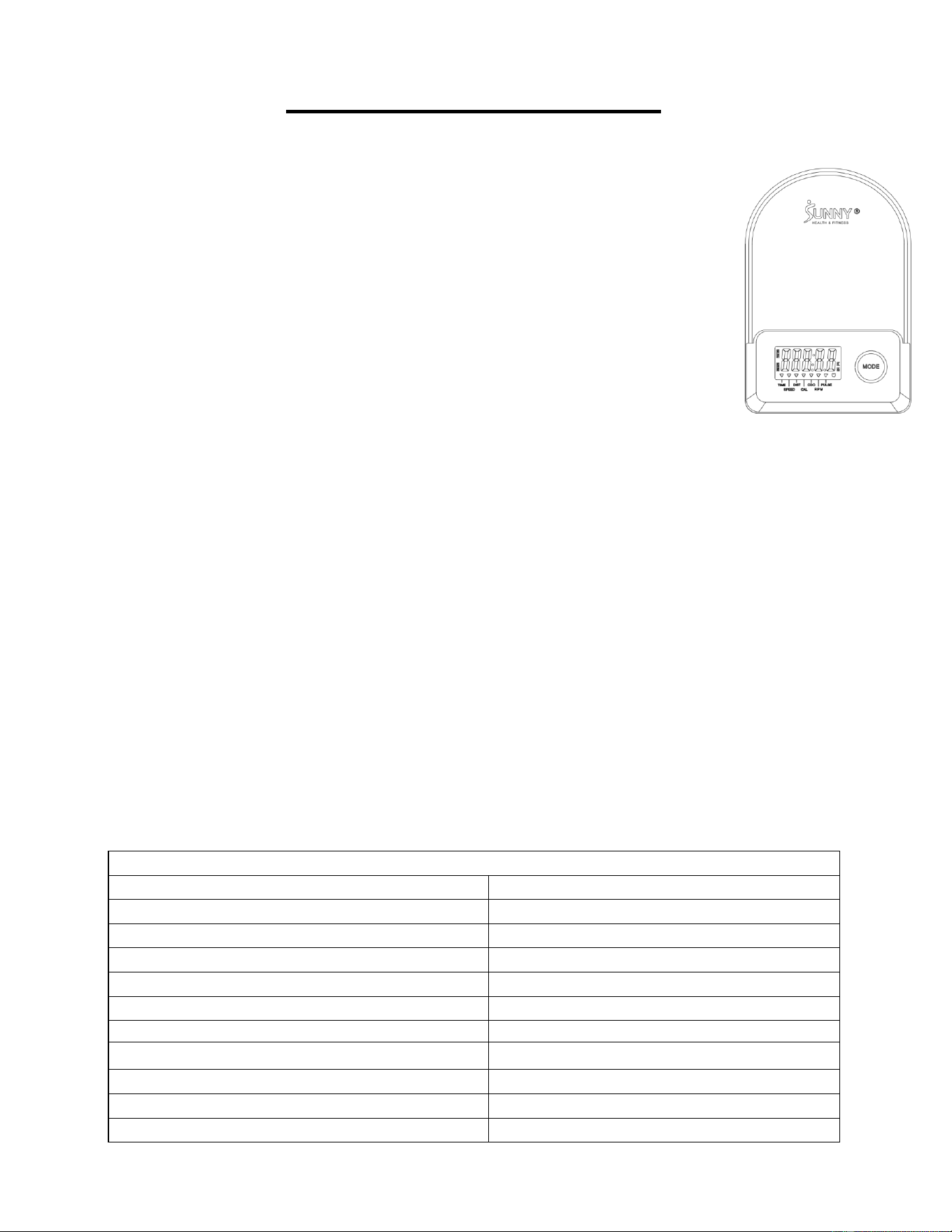
EXERCISE METER
FUNCTION BUTTONS
MODE:
1. Pressing the MODE key to select and lock on a function.
2. Press and hold the MODE key for 3 seconds to reset all the values to
zero, except ODO (TOTAL DISTANCE).
SLEEP MODE:
1. The system turns on when the MODE key is pressed or senses a
signal input from the sensor.
2. The system turns off automatically when the sensor has no signal
input or no key is pressed for approximately 4 minutes.
FUNCTIONS:
1. SCAN: Display changes according to the next diagram every 6 seconds in the following
sequence: TIME- SPEED- DIST (DISTANCE) - CAL (CALORIES) - ODO (TOTAL
DISTANCE) - RPM (CADENCE) - PULSE.
2. SPEED: The current speed from starting exercise.
3. DIST (DISTANCE): The current distance from starting exercise.
4. TIME: The time elapsed from starting exercise.
5. ODO (TOTAL DISTANCE): The total distance which from first inserting batteries.
6. CAL (CALORIES): The calories burned from starting exercise.
7. RPM (CADENCE): The frequency per minute from starting exercise.
8. PULSE: The current heart rate from starting exercise.
NOTE:
1. If the meter display is abnormal, please re-install the batteries and try again.
2. Battery Spec: 1.5V UM-4 or AAA (2PCS).
3. The batteries must be removed from the appliance before it is disposed of safely.
SPECIFICATION
SCAN
6S
TIME
0:00~99:59 (M:S)
SPEED
0.0~999.9 Miles/Hour
DIST (DISTANCE)
0.00~999.9 Miles
ODO (TOTAL DISTANCE)
0.0~999.9 Miles
CAL (CALORIES)
0.0~999.9 Kcal
RPM (CADENCE)
0~299
PULSE
40~240 BPM (Beats per Minute)
BATTERY
SIZE-AAA *2
OPERATING TEMPERATURE
0~40℃ (32℉-104℉)
STORAGE TEMPERATURE
-10~60℃ (14℉-140℉)
12
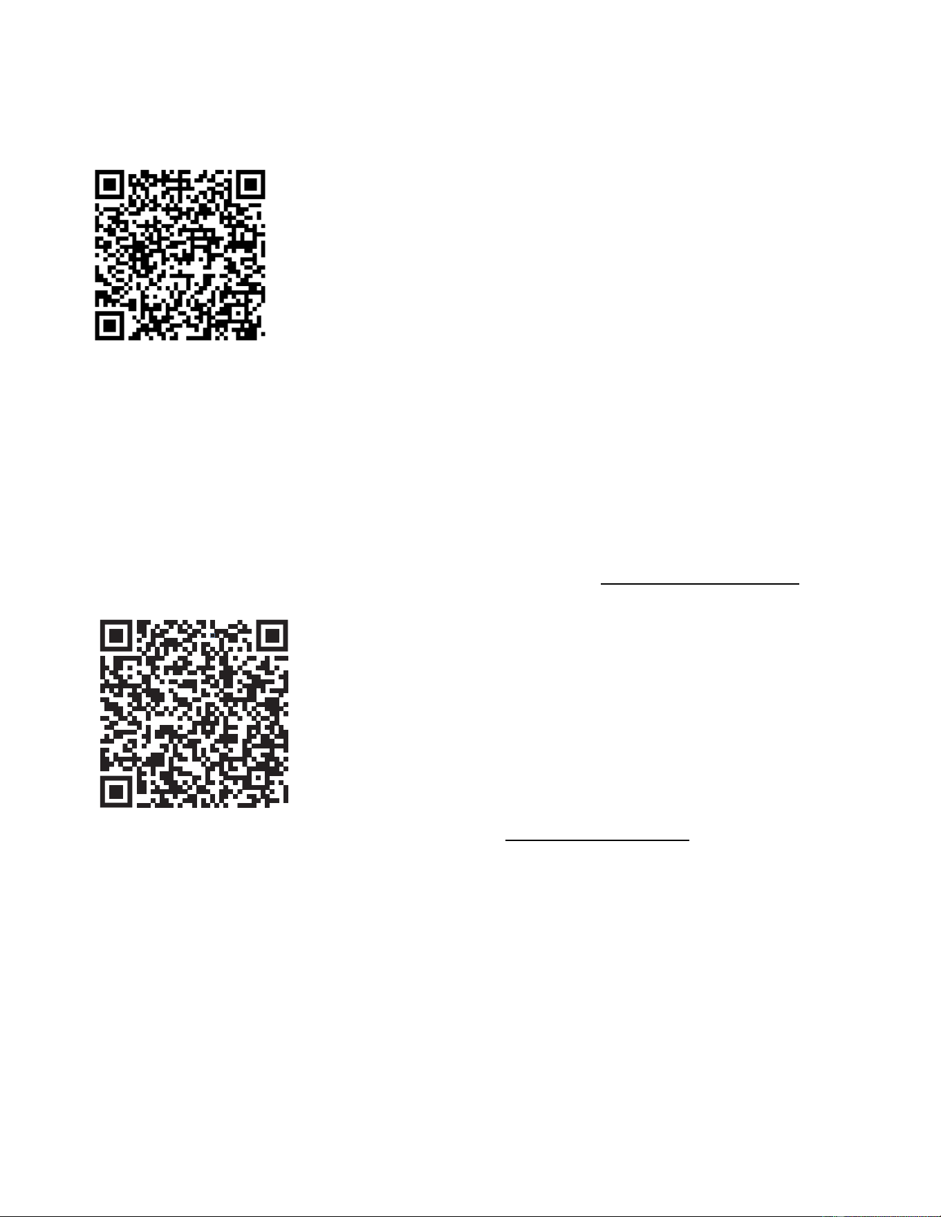
APP CONNECTION:
Connect Smart Equipment to SunnyFit App:
1. Scan to download SunnyFit from the app store:
2. Ensure that the Bluetooth function is turned on from your mobile device.
3. If this is your first time using the SunnyFit app, follow the in-app instructions to register for
your free SunnyFit account and log in.
4. Begin any workout activity that matches your smart equipment, then follow the onscreen
prompts to search for and connect to your smart equipment.
5. When connected, your stats and records will be displayed at the end of your course/session,
and recorded in your account profile!
Troubleshooting:
•
If you are having trouble connecting your smart equipment, visit www.sunnyfit.com/guide or
scan the QR code below:
•
If you require additional support, please contact [email protected].

13
MAINTENANCE INSTRUCTIONS
This is general information for daily, weekly, and monthly maintenance to be performed on your bike.
Version 1.3
DAILY MAINTENANCE
After each exercise session, wipe down all
the equipment: seat, frame, and handlebars.
Pay special attention to the seat post,
handlebar post and belt/chain guard. Sweat
is very corrosive and may cause problems
that require parts replacement later.
1. Get on the bike and engage the drive
train.
2. Pay attention to any vibrations felt
through the pedals. If you feel any
vibrations, you may need to tighten the
pedals, bottom bracket, or adjust the drive
belt/chain tension.
3. Use a spanner to tighten the pedals until
they are secure.
MONTHLY MAINTENANCE
1. Check all hardware is secure, such as: bottle
holder, flywheel nuts, belt/chain guard bolts,
brake caliper lock nuts and brake caliper
tension rod nuts.
2. Inspect the brake tension rod for signs of
wear such as missing threads. Clean and
lubricate the brake tension rod.
3. Clean and lubricate the seat post, handlebar
post and seat slider. Remove any buildup of
foreign material.
WEEKLY MAINTENANCE
1. Inspect moving parts and tighten the
hardware.
2. Inspect pull pin frame fittings, making
sure the fittings are snug. Loose frame
fittings may strip out threads over time
and cause extensive damage.
3. Clean and lubricate pop pin assemblies.
Pull on the pin and spray a small amount
of lubricant onto the shaft.
4. Tighten the seat hardware, making sure
the seat is level and centered.
5. Brush and treat the resistance pads.
Remove any foreign material that may
have collected on the pads. Spray the
pads with silicone lubricant. This helps to
reduce noise from friction between the
pads and the flywheel.
6. Visually inspect the bottom bracket, toe
clips and toe straps. If any of them are
loose or disconnected, attach and tighten.
LEATHER BRAKE PAD CARE (If Applicable)
1. Perform this maintenance when the brake
pad is first installed and for the life of the
brake pad. Following these simple
guidelines can increase the life of your
brake pads.
2. Some brake pad assemblies are pre-
lubricated. Squeeze the brake pad. If
lubricant is released, then the pad has been
pre-lubricated.
3. If the brake pad is dry, then coat the brake
pad with 3-n-1 oil. Brush the leather with a
clean, wire bristle brush, and then apply the
oil. The oil should be allowed to soak into
the pad. Repeat 4-5 times until the pad is
saturated, but not dripping with oil. When
the pad is saturated, it will no longer absorb
oil.
4. Inspect the brake pad weekly and lubricate
if needed. The pad should not have a
glazed appearance. If the pad appears
glazed, then brush it with wire brush and
apply lubricant as needed. If any of the
sponge padding is showing through the
leather pad, the brake pad should be
replaced.

14
PARTS LIST
No.
Description
Spec.
Qty.
No.
Description
Spec.
Qty.
1
Main Frame
1
32
Sensor Wire
L850
1
2
Handlebar Post
1
33a
Pulse Wire A
L650
1
3
Seat Post
1
33b
Pulse Wire B
L650
1
4
Handlebar
1
34
Meter Bracket
1
5
Seat Slider
Sea
1
35
Bottle Holder
1
6
Front Stabilizer
80X40X1.2X460
1
36
Screw with Washer
M5X16
2
7
Rear Stabilizer
80X40X1.2X500
1
37
Screw
M4X15
1
8
Phillips Screw
ST4.2X16
19
38
Nut
M4
1
9
Screw
M8X15
4
39
Dumbbell Rack
1
10
Flat Washer
D8X1.5XΦ16
8
40
Phillips Screw
M5X12
2
11
Flat Washer
D10X2XΦ25
1
41
Limited Block
Φ17X10
2
12
Spring Washer
D8
8
42L
Left Nylon Nut
9/16X20XH9XS19
1
13
Cap Nut
M8
5
42R
Right Nylon Nut
9/16X20XH9XS19
1
14
Carriage Bolt
M8XL55
4
43
Cross Countersunk
Head Screw
ST4.2X16
6
15L
Left Front End Cap
80X40X1.5
1
44
Bolt
M6X15
6
15R
Right Front End Cap
80X40X1.5
1
45
Washer
D6XD12X1.2
2
16L
Left Crank
9/16’’X20
1
46
Screw
ST4X10
5
16R
Right Crank
9/16’’X20
1
47
Spring Washer
D6
6
17
Rear End Cap
80X40X1.5
2
48
Wave Washer
D20XΦ28X0.3
1
18
Handlebar Cover
1
49
Wave Washer
D12XΦ17X0.3
1
19
Tension Control Knob
Φ60X45
1
50
Axle Spring Washer
D20
2
20
Sleeve
80X40X1.2
2
51
Axle Spring Washer
D12
2
21L
Left Pedal
9/16’’X20
1
52
Hex Thin Nut
M12X1
1
21R
Right Pedal
9/16’’X20
1
53
Hex Conical Thin Nut
M12X1
1
22
Seat
KX8022
1
54
Cap Nut
M12X1
2
23
Square Plug
40X20X1.5
2
55
Hex Nut
M8
3
24
Round Cap
Φ28X1.5
2
56
Nylon Nut
M8
2
25
Round Cap
Φ19X1.5
1
57
Nylon Nut
M6
4
26
Adjustment Knob
M16X1.5X22
2
58
Square Nut
20X20XM10
1
27
Adjustment Knob
Φ50X20
1
59
Nut
M12X1.25
2
28
Plug
Φ12.5
3
60
Brake Rod
Φ10X193
1
29
Foam Grip
Φ27XT3X410
2
61
Center Axle
Φ20X150
1
30
Pulse Sensor
2
62
Flywheel Axle
M12XL150XL28XL42
1
31
Meter
BJHT-087
1
63
Flywheel
Φ420X26, 6kgs
1
31a
Meter Wire A
1
64
Bearing
6004
2
31b
Meter Wire B
1
65
Bearing
6001
2
31c
Meter Wire C
1
66
Sleeve
Φ12.2XΦ18X14
1
15
No.
Description
Spec.
Qty.
No.
Description
Spec.
Qty.
67
Sleeve
Φ12.2XΦ18X4
2
82
Belt Pulley
Φ240X20
1
68
Flywheel Sleeve
Φ18XΦ12.2X65.2
1
83
Belt
500PJ6
1
69
Adjusting Belt Bolt
M8X48
2
84
Sleeve
Φ18X3XΦ14X7XΦ10X10
1
70
Magnet
25X10X5
8
85
Flywheel Cover
2
71
Magnetic Board Axle
Φ12XL28.6XM6
1
86
Sensor Bracket
1
72
Pull Spring
Φ14.5XΦ1.6Φ61.2
1
87
Brake Sheet
9X35X26
1
73
Outer Belt Cover
1
88
Cross Countersunk
Head Screw
M5X12
2
74
Inner Belt Cover
1
89
Screw
M6X8
2
75
Crank Cover
Φ46
1
90
Screw
M16X1.5X30
1
76
Cap
Φ25
2
91
Shipping Tube 1
1
77
Front Protective
Cover
1
92
Shipping Tube 2
80X40X1.2X170
1
78
Upper Protective
Cover
1
93
Cap
80X40X1.5
2
79
Brake Cover
1
94
Allen Wrench
S6
1
80
Magnetic Board
1
95
Spanner
S13,S14,S15
1
81
Washer
D10.5XΦ20X2
1
96
Spanner
S17,S19
1

16
INFORMACIÓN IMPORTANTE SOBRE SEGURIDAD
Le agradecemos que haya elegido nuestro producto. Para garantizar su seguridad y su salud,
utilice este equipo correctamente. Es importante leer este manual en su totalidad antes de
montar y utilizar el equipo. Sólo se puede lograr un uso seguro y eficaz si el equipo se monta,
mantiene y utiliza correctamente. Es su responsabilidad asegurarse de que todos los usuarios
del equipo estén informados de todas las advertencias y precauciones.
1. Antes de iniciar cualquier programa de ejercicios, debe consultar a su médico para
determinar si tiene alguna condición médica o física que pudiera poner en riesgo su salud y
seguridad, o impedirle utilizar el equipo adecuadamente. El consejo de su médico es
esencial si está tomando medicación que afecte a su ritmo cardíaco, presión arterial o nivel
de colesterol.
2. Esté atento a las señales de su cuerpo. Un ejercicio incorrecto o excesivo puede perjudicar
su salud. Deje de hacer ejercicio si experimenta alguno de los síntomas siguientes: dolor,
opresión en el pecho, latidos irregulares del corazón, dificultad para respirar, aturdimiento,
mareos o sensación de náuseas. Si experimenta alguna de estas condiciones, debe
consultar a su médico antes de continuar con su programa de ejercicios.
3. Mantenga a los niños y a las mascotas alejados del equipo. El equipo está diseñado para
uso exclusivo de adultos.
4. Utilice el equipo sobre una superficie sólida, plana y nivelada con una cubierta protectora
para su suelo o alfombra. Para garantizar la seguridad, el equipo debe tener al menos 60
cm (2 pies) de espacio libre a su alrededor.
5. Asegúrese de que todas las tuercas y tornillos estén bien apretados antes de utilizar el
equipo. La seguridad del equipo sólo puede mantenerse si se examina regularmente para
detectar daños y/o desgaste.
6. Utilice siempre el equipo tal y como se indica. Si encuentra algún componente defectuoso
mientras ensambla o revisa el equipo, o si escucha algún ruido inusual proveniente del
equipo durante el ejercicio, interrumpa inmediatamente el uso del equipo y no lo utilice hasta
que el problema haya sido rectificado.
7. Lleve ropa adecuada cuando utilice el aparato. Evite llevar ropa suelta que pueda enredarse
en el equipo.
8. No introduzca los dedos ni objetos en las partes móviles del equipo.
9. La capacidad máxima de peso de esta unidad es de 135 kgs (300 lbs).
10. El equipo no es adecuado para uso terapéutico.
11. Para evitar lesiones corporales y/o daños al producto o a la propiedad, es necesario
levantar y mover el equipo adecuadamente.
12. Su producto está diseñado para ser utilizado en condiciones frescas y secas. Debe evitar
almacenarlo en zonas extremadamente frías, calientes o húmedas, ya que esto puede
provocar corrosión y otros problemas relacionados.
13. Este equipo está diseñado únicamente para uso doméstico y en interiores. No está
diseñado para uso comercial.
17
LISTA DE COMPROBACIÓN PREVIA AL MONTAJE
Antes de empezar a montar, asegúrese de que se incluyen todas las piezas.
n.°
Descripción
Espec.
Cant.
n.°
Descripción
Espec.
Cant.
1
Bastidor Principal
1
22
Asiento
KX8022
1
2
Tija del Manillar
1
26
Pomo de Ajuste
M16X1.5X22
1
3
Tija de Sillín
1
31
Medidor
BJHT-087
1
4
Manillar
1
35
Soporte Botella
1
5
Deslizador de Asiento
1
39
Soporte Mancuernas
1
6
Estabilizador Delantero
80X40X1.2X460
1
A
Manual
1
7
Estabilizador Trasero
80X40X1.2X500
1
B
Paquete de Hardware
1
18
Tapa del Manillar
1
C
Tarjeta de
Agradecimiento
1
21L
Pedal Izquierdo
9/16“X20
1
D
Batería
AAA
2
21R
Pedal Derecho
9/16“X20
1

18
PAQUETE DE HARDWARE
Pedido de piezas de repuesto (sólo para clientes de EE.UU. y Canadá)
Proporcione la siguiente información para que podamos identificar con precisión la(s) pieza(s)
necesaria(s):
✓ El número de modelo (se encuentra en la portada del manual)
✓ Nombre del producto (en la portada del manual)
✓ El número de pieza que se encuentra en el «DIAGRAMA EXPLÍCITO» (páginas 31~32) y en
la «LISTA DE PIEZAS» (páginas 29~30)
Póngase en contacto con nosotros en [email protected] o en el 1-877-
90SUNNY (877-907-8669).
19
INSTRUCCIONES DE MONTAJE
Valoramos su experiencia con los productos Sunny Health and Fitness. Para obtener ayuda con las
piezas o la resolución de problemas, póngase en contacto con nosotros en
PASO 1:
Retire los 2 Pernos de Carro (n.° 14), las 2
Arandelas Planas (n.° 10), las 2 Tuercas
Ciega (n.° 13) y las 2 Arandelas Elásticas
(n.° 12) del Tubo de Transporte 2 (n.° 92)
con la Llave (n.° 95).
Retire el Tornillo (n.° 90) con la Llave (n.°
96) y saque el Tubo de Transporte 1 (n.° 91)
del Bastidor Principal (n.° 1).
NOTA: Puede guardar estas piezas: Tubo
de Transporte 2 (n.° 92) y Tubo de
Transporte 1 (n.° 91) para el futuro
embalaje y transporte de la bicicleta.
PASO 2:
Fije el Estabilizador Trasero (n.° 7) al
Bastidor Principal (n.° 1) utilizando 2
Pernos de Carro (n.° 14), 2 Arandelas
Planas (n.° 10), 2 Tuercas Ciegas (n.° 13) y
2 Arandelas Elásticas (n.° 12) que acaba de
retirar en el PASO 1. Apriételos y fíjelos con
la Llave (n.° 95).
Fije el Estabilizador Delantero (n.° 6) al
Bastidor Principal (n.° 1) utilizando 2
Pernos de Carro (n.° 14), 2 Arandelas
Planas (n.° 10), 2 Tuercas Ciegas (n.° 13) y
2 Arandelas Elásticas (n.° 12). Apriete y
asegure con la Llave (n.° 95).
20
Valoramos su experiencia con los productos Sunny Health and Fitness. Para obtener ayuda con las
piezas o la resolución de problemas, póngase en contacto con nosotros en
PASO 3:
¡IMPORTANTE! Lea atentamente las
instrucciones, de lo contrario podría causar
daños permanentes a su bicicleta.
Retire las Tuercas de Nylon Izquierda y
Derecha (n.° 42L y n.° 42R) situadas en los
Pedales Izquierdo y Derecho (n.° 21L y n.°
21R) con la Llave (n.° 96) y la Llave (n.° 95).
La Tuerca de Nylon Derecha (n.° 42R) es
BLANCA por dentro. La Tuerca de Nylon
Izquierda (n.° 42L) es AZUL por dentro. El
Pedal Izquierdo (n.° 21L) tiene la marca «L»,
el Pedal Derecho (n.° 21R) tiene la marca
«R».
Alinee el Pedal Izquierdo (n.° 21L) con la
Manivela Izquierda (n.° 16L) a 90°. Gire el
tornillo del Pedal Izquierdo (n.° 21L) en
sentido contrario a las agujas del reloj tanto
como pueda con la mano. A continuación,
utilice la Llave (Nº 95) para apretar y asegurar.
Gire la Tuerca de Nylon Izquierda (n.° 42L)
en el sentido de las agujas del reloj tanto
como pueda con la mano. Utilice la Llave
Inglesa (n.° 95) para sujetar el perno del Pedal
Izquierdo (n.° 21L) y la Llave (n.° 96) para
girar la Tuerca de Nylon Izquierda (n.° 42L)
en el sentido de las agujas del reloj al mismo
tiempo, hasta que quede apretada en la
Manivela Izquierda (n.° 16L).
Alinee el Pedal Derecho (n.° 21R) con la
Manivela Derecha (n.° 16R) a 90°. Gire el
perno del Pedal Derecho (n.° 21R) en el
sentido de las agujas del reloj lo más fuerte
que pueda con la mano. A continuación, utilice
la Llave (n.° 95) para apretar y asegurar. Gire
la Tuerca de Nylon Derecha (n.° 42R) en
sentido contrario a las agujas del reloj tanto
como pueda con la mano. Utilice la Llave (n.°
95) para sujetar el perno del Pedal Derecho
(n.° 21R) y la Llave (n.° 96) para girar la
Tuerca de Nylon Derecha (n.° 42R) en
sentido contrario a las agujas del reloj al
mismo tiempo, hasta que quede apretada en la
Manivela Derecha (n.° 16R).
21
Valoramos su experiencia con los productos Sunny Health and Fitness. Para obtener ayuda con las
piezas o la resolución de problemas, póngase en contacto con nosotros en
PASO 4:
Afloje y extraiga el Pomo de Ajuste (n.° 26).
Inserte la Tija de Sillín (n.° 3) en el manguito
ubicado en el Bastidor Principal (n.° 1) y
luego fíjela con la Pomo de Ajuste (n.° 26).
Inserte el Deslizador de Asiento (n.° 5) en la
Tija de Sillín (n.° 3) y bloquéelo con la Pomo
de Ajuste (n.° 27) y la Arandela Plana (n.°
11) después de ajustarlo en el orificio E o F
del Deslizador de Asiento (n.° 5).
Fije el Asiento (n.° 22) al Deslizador de
Asiento (n.° 5). Apriete y asegure con la
Llave (n.° 95).
NOTA: Asegúrese de que el Asiento (n.° 22)
esté bien trabado en la Deslizador de
Asiento (n.° 5) antes del ejercicio.
PASO 5
Inserte el Tija del Manillar (n.° 2) en el
manguito del Bastidor Principal (n.° 1) y, a
continuación, bloquéelo con el Pomo de
Ajuste (n.° 26).
Quite 4 Tornillos (n.° 9), 4 Arandelas
Elásticas (n.° 12) y 4 Arandelas Planas (n.°
10) del Tija del Manillar (n.° 2) con la Llave
Allen (n.° 94).
Fije el Manillar (n.° 4) al Tija del Manillar
(n.° 2) con los 4 Tornillos (n.° 9), las 4
Arandelas Elásticas (n.° 12) y las 4
Arandelas Planas (n.° 10) que acaba de
retirar. Apriételos y fíjelos con la Llave Allen
(n.° 94).
22
Valoramos su experiencia con los productos Sunny Health and Fitness. Para obtener ayuda con las
piezas o la resolución de problemas, póngase en contacto con nosotros en
PASO 6:
Inserte el Medidor (n.° 31) en el Soporte
del Medidor (n.° 34), luego conecte el
Cable del Sensor (n.° 32) y el Cable C
del Medidor (n.° 31c), conecte el Cable
de Impulsos A (n.° 33a) con el Cable A
del Medidor (n.° 31a) y conecte el Cable
de Impulsos B (n.° 33b) con el Cable B
del Medidor (n.° 31b).
Coloque la Tapa del Manillar (n.° 18) en
la posición G.
PASO 7:
Fije el Soporte Botella (n.° 35) al
Bastidor Principal (n.° 1) con 2 Tornillo
con Arandela (n.° 36) utilizando la Llave
(n.° 95).
Fije el Soporte Mancuernas (n.° 39) al
Deslizador de Asiento (n.° 5) con 2
Tornillos (n.° 40). Apriételos y fíjelos con
la Llave (n.° 95).
El montaje está complete!
23
GUÍA DE AJUSTE
AJUSTE DEL MANILLAR:
Es importante que tanto el manillar como el asiento estén ajustados
a la altura correcta de su cuerpo. Para ajustar la altura del manillar,
afloje y tire de la Pomo de Ajuste (n.° 26) hacia fuera, luego
deslice el Tija del Manillar (n.° 2) hacia arriba o hacia abajo hasta
la altura deseada. Una vez ajustado, vuelva a insertar y apretar el
Pomo de Ajuste (n.° 26) para fijar el Tija del Manillar (n.° 2) en su
sitio.
TRANSPORTE DE LA BICICLETA:
Para desplazar la bicicleta, asegúrese primero de que el Manillar
(n.° 4) esté bien sujeto. Si el Manillar (n.° 4) está flojo, apriete la
Pomo de Ajuste (n.° 26) para asegurarlo. A continuación,
colóquese en la parte delantera de la bicicleta de modo que esté
directamente delante del Manillar (n.° 4). Sujete firmemente cada
lado del Manillar (n.° 4), coloque un pie en el Estabilizador
Delantero (n.° 6) e incline la bicicleta hacia usted hasta que las
ruedas de las Tapas Delanteras Izquierda y Derecha (n.° 15L y
n.° 15R) toquen el suelo. Con las ruedas en el suelo, podrá
transportar la bicicleta al lugar deseado con facilidad.
NOTA: Al mover la bicicleta, tenga siempre cuidado, ya que un
impacto inesperado, como la caída de la bicicleta, puede causar
lesiones y afectar al rendimiento de la bicicleta.
AJUSTE DEL ASIENTO:
El asiento de esta motocicleta es totalmente ajustable, ya que se
mueve hacia arriba, hacia abajo, hacia adelante y hacia atrás.
Para ajustar la altura de la Tija del Sillín (n.° 3), afloje y tire del
Pomo de Ajuste (n.° 26) hacia fuera y, a continuación, suba o baje
el sillín hasta la altura deseada. Una vez ajustada, vuelva a insertar
y apretar la Pomo de Ajuste (n.° 26) para fijar la Tija del Sillín (n.°
3) en su lugar.
Para ajustar el asiento hacia adelante y hacia atrás, afloje la Pomo
de Ajuste (n.° 27) y mueva el Deslizador de Asiento (n.° 5) hasta
la posición deseada. Una vez posicionado, reinserte y apriete la
Pomo de Ajuste (n.° 27) para asegurar el tubo del Deslizador de
Asiento (n.° 5) en su lugar. Puede cambiar la posición del orificio
de la Pomo de Ajuste (n.° 27) para aumentar el rango de ajuste.
Para cambiar la posición del orificio, retire la Pomo de Ajuste (n.°
27) y la Arandela Plana (n.° 11), luego ajuste el Deslizador de
Asiento (n.° 5) en el orificio deseado (E o F). Una vez ajustado,
vuelva a apretar el Deslizador de Asiento (n.° 5) con la Pomo de
Ajuste (n.° 27) y la Arandela Plana (n.° 11) que acaba de retirar.
24
APRETAR EL ASIENTO:
Si el Asiento (n.° 22) está flojo, ajústelo con la Llave (n.° 95).
AJUSTE DEL EQUILIBRIO:
Si la moto no está nivelada, ajuste los Tapas Traseras (n.° 17).
Gire en sentido contrario a las agujas del reloj para elevar, gire en
sentido de las agujas del reloj para bajar.
AJUSTE DE LA RESISTENCIA:
Ajuste la resistencia de la bicicleta con el Pomo de Control de
Tensión (n.° 19). Aumente el nivel de resistencia girando el Pomo
de Control de Tensión (n.° 19) hacia la DERECHA (en el sentido
de las agujas del reloj), disminuya el nivel de resistencia girando el
Pomo de Control de Tensión (n.° 19) hacia la IZQUIERDA (en el
sentido contrario a las agujas del reloj). Empuje hacia abajo el
Pomo de Control de Tensión (n.° 19) para el freno de emergencia.
AJUSTE DE LA CORREA DEL PEDAL:
Coloque la bola de cada pie en los clips de los dedos de modo que
la parte delantera de su zapato encaje perfectamente en la jaula del
clip de los dedos (I). Gire un pie hasta que quede al alcance de la
mano y tire de la correa (H) hasta que la jaula del clip superior (I) se
ajuste perfectamente a su zapato. Vuelva a introducir la correa en el
aro del clip para dedos. Repita esta operación con el otro pie.
DESMONTAJE
Por su seguridad, se recomienda que nunca intente desmontar o retirar los pies de los pedales
hasta que tanto el volante de inercia como los pedales/manivelas se hayan detenido por completo.
El incumplimiento de esta recomendación puede provocar la pérdida de control y/o lesiones graves.
He aquí algunos ejemplos de cómo desmontar la bicicleta de forma segura:
1. Reduzca la velocidad de pedaleo hasta que los pedales/manivelas se detengan por completo.
2. Aumente la resistencia hasta que los pedales/manivelas se detengan por completo.
3. Mantenga pulsado el mando de control de la tensión hasta que los pedales/manivelas se
detengan por completo.
25
INSTALACIÓN Y SUSTITUCIÓN DE BATERÍAS
INSTALACIÓN DE LA BATERÍA
1. Extraiga 2 baterías AAA de la caja del medidor.
2. Presione la hebilla de la tapa de las baterías en el Medidor (n.° 31) y, a continuación, retire la
tapa de las baterías.
3. Instale 2 baterías AAA en el estuche de las baterías en la parte posterior del Medidor (n.° 31).
Preste atención a los polos + y - de las baterías antes de instalarlas.
4. Presione la hebilla de la tapa de las baterías y vuelva a colocarla en la parte posterior del
Medidor (n.° 31).
La instalación ha finalizado!
SUSTITUCIÓN DE LA BATERÍA
1. Presione la hebilla de la tapa de la batería en la parte posterior del Medidor (n.° 31), luego
retire la tapa de la batería.
2. Retire las 2 baterías AAA viejas del estuche de las baterías e instale 2 baterías AAA nuevas
en el estuche de las baterías en la parte posterior del Medidor (n.° 31). Preste atención a
los polos + y - de las baterías antes de instalarlas.
3. Presione la hebilla de la tapa de las baterías y vuelva a colocar la tapa en la parte posterior
del Medidor (n.° 31).
La sustitución se ha completado!
ELIMINACIÓN DE BATERÍAS
Deseche las baterías de acuerdo con las leyes y reglamentos locales de su región. Algunas
baterías pueden ser recicladas. Al desechar o reciclar, no mezcle tipos de baterías.
Tapa de la Batería
Batería
31
26
MEDIDOR DE EJERCICIO
BOTONES DE FUNCIÓN
MODE:
1. Pulse la tecla MODE para seleccionar y bloquear una función.
2. Mantenga pulsada la tecla MODE durante 3 segundos para poner a
cero todos los valores, excepto ODO (DISTANCIA TOTAL).
MODO SUEÑO:
1. El sistema se enciende cuando se pulsa la tecla MODE o detecta una
entrada de señal del sensor.
2. El sistema se apaga automáticamente cuando el sensor no tiene
entrada de señal o no se pulsa ninguna tecla durante
aproximadamente 4 minutos.
FUNCIONES:
1. SCAN: La pantalla cambia según el siguiente diagrama cada 6 segundos en la siguiente
secuencia: TIME (TIEMPO)- SPEED (VELOCIDAD)- DIST (DISTANCIA) - CAL (CALORÍAS)
- ODO (DISTANCIA TOTAL) - RPM (CADENCIA) – PULSE (PULSO).
2. SPEED (VELOCIDAD): La velocidad actual desde el inicio del ejercicio.
3. DIST (DISTANCIA): La distancia actual desde el inicio del ejercicio.
4. TIME (TIEMPO): El tiempo transcurrido desde el inicio del ejercicio.
5. ODO (DISTANCIA TOTAL): La distancia total que desde la primera inserción de las baterías.
6. CAL (CALORÍAS): Las calorías quemadas desde el inicio del ejercicio.
7. RPM (CADENCIA): La frecuencia por minuto desde el inicio del ejercicio.
8. PULSE (PULSO): La frecuencia cardíaca actual desde el inicio del ejercicio.
NOTA:
1. Si la pantalla del medidor es anormal, por favor, vuelva a instalar las baterías y vuelva a
intentarlo.
2. Batería Spec: 1.5V UM-4 o AAA (2PCS).
3. Las baterías deben retirarse del aparato antes de desecharlo de forma segura.
ESPECIFICACIÓN
SCAN
6S
TIME (TIEMPO)
0:00~99:59 (M:S)
SPEED (VELOCIDAD)
0.0~999.9 Millas/Hora
DIST (DISTANCIA)
0.00~999.9 Millas
ODO (DISTANCIA TOTAL)
0.0~999.9 Millas
CAL (CALORÍAS)
0.0~999.9 Kcal
RPM (CADENCIA)
0~299
PULSE (PULSO)
40~240 BPM (Pulsaciones por Minuto)
BATERÍA
TALLA-AAA *2
TEMPERATURA DE FUNCIONAMIENTO
0~40℃ (32℉-104℉)
TEMPERATURA DE ALMACENAMIENTO
-10~60℃ (14℉-140℉)
27
CONEXIÓN A LA APP:
Conecte el equipo inteligente a la SunnyFit App:
1. Escanee para descargar SunnyFit desde la tienda de aplicaciones:
2. Asegúrese de que la función Bluetooth está activada desde su dispositivo móvil.
3. Si es la primera vez que utiliza la app SunnyFit, siga las instrucciones de la app para
registrarse en su cuenta gratuita de SunnyFit e iniciar sesión.
4. Comience cualquier actividad de entrenamiento que coincida con su equipo inteligente y, a
continuación, siga las indicaciones en pantalla para buscar y conectarse a su equipo
inteligente.
5. Una vez conectado, sus estadísticas y récords se mostrarán al final de su curso/sesión y se
registrarán en el perfil de su cuenta.
Solución de problemas:
•
Si tiene problemas para conectar su equipo inteligente, visite www.sunnyfit.com/guide o
escanee el código QR que aparece a continuación:
•
Si necesita más ayuda, póngase en contacto con [email protected].

28
INSTRUCCIONES DE MANTENIMIENTO
Esta es información general para el mantenimiento diario, semanal y mensual que debe realizar en su motocicleta.
MANTENIMIENTO DIARIO
Después de cada sesión de ejercicio, limpie todo
el equipo: sillín, cuadro y manillar. Preste
especial atención a la tija del sillín, la tija del
manillar y el protector del cinturón/cadena. El
sudor es muy corrosivo y puede causar
problemas que requieran la sustitución de piezas
más adelante.
1. Súbase a la bicicleta y engrane la
transmisión.
2. Preste atención a cualquier vibración que
sienta a través de los pedales. Si nota alguna
vibración, es posible que tenga que apretar
los pedales, el pedalier o ajustar la tensión de
la correa de transmisión/cadena.
3. Utilice una llave inglesa para apretar los
pedales hasta que queden bien sujetos.
MANTENIMIENTO MENSUAL
1. Compruebe que toda la tornillería está bien
sujeta, como por ejemplo: el soporte de la
botella, las tuercas del volante, los pernos
del protector de la correa/cadena, las
tuercas de bloqueo de la pinza de freno y las
tuercas de la varilla tensora de la pinza de
freno.
2. Inspeccione la varilla tensora del freno en
busca de signos de desgaste, como roscas
faltantes. Limpie y lubrique la varilla tensora
del freno.
3. Limpie y lubrique la tija del sillín, la tija del
manillar y el deslizador del sillín. Elimine
cualquier acumulación de materiales
extraños.
MANTENIMIENTO SEMANAL
1. Inspeccione las piezas móviles y apriete los
herrajes.
2. Inspeccione los herrajes del bastidor del
pasador de tracción, asegurándose de que
estén bien apretados. Los herrajes del
bastidor flojos pueden desprender las roscas
con el tiempo y causar grandes daños.
3. Limpie y lubrique los conjuntos de pasador de
seguridad. Tire del pasador y rocíe una
pequeña cantidad de lubricante en el eje.
4. Apriete los herrajes del asiento,
asegurándose de que el asiento esté
nivelado y centrado.
5. Cepille y trate las almohadillas de resistencia.
Elimine cualquier material extraño que pueda
haberse acumulado en las almohadillas.
Rocíe las pastillas con lubricante de silicona.
Esto ayuda a reducir el ruido de la fricción
entre las almohadillas y el volante.
6. Inspeccione visualmente el eje de pedalier,
las abrazaderas de los dedos y las correas
de los dedos. Si alguno de ellos está suelto o
desconectado, fíjelo y apriételo.
CUIDADO DE LAS PASTILLAS DE FRENO
DE CUERO (si procede)
1. Realice este mantenimiento cuando instale las
pastillas de freno por primera vez y durante toda
su vida útil. Seguir estas sencillas pautas puede
aumentar la vida útil de las pastillas de freno.
2. Algunos conjuntos de pastillas de freno están
prelubricados. Apriete la pastilla de freno. Si sale
lubricante, entonces la pastilla ha sido
prelubricada.
3. Si la pastilla de freno está seca, úntela con
aceite 3-n-1. Cepille el cuero con un cepillo
limpio de cerdas de alambre y, a continuación,
aplique el aceite. Deje que el aceite penetre en
la pastilla. Repita la operación 4-5 veces hasta
que la pastilla esté saturada, pero no goteando
aceite. Cuando la almohadilla esté saturada, ya
no absorberá aceite.
4. Inspeccione la pastilla de freno semanalmente y
lubríquela si es necesario. La pastilla no debe
tener un aspecto vidrioso. Si la pastilla parece
vidriosa, cepíllela con un cepillo de alambre y
aplique lubricante según sea necesario. Si la
almohadilla de esponja se ve a través de la
almohadilla de cuero, la almohadilla de freno
debe ser reemplazada.

29
LISTA DE PIEZAS
n.°
Descripción
Espec.
Cant.
n.°
Descripción
Espec.
Cant.
1
Bastidor Principal
1
32
Cable del Sensor
L850
1
2
Tija del Manillar
1
33a
Cable de Impulsos A
L650
1
3
Tija de Sillín
1
33b
Cable de Impulsos B
L650
1
4
Manillar
1
34
Soporte del Medidor
1
5
Deslizador de Asiento
Sea
1
35
Soporte Botella
1
6
Estabilizador Delantero
80X40X1.2X460
1
36
Tornillo con Arandela
M5X16
2
7
Estabilizador Trasero
80X40X1.2X500
1
37
Tornillo
M4X15
1
8
Tornillo Phillips
ST4.2X16
19
38
Tuerca
M4
1
9
Tornillo
M8X15
4
39
Soporte Mancuernas
1
10
Arandela Plana
D8X1.5XΦ16
8
40
Tornillo Phillips
M5X12
2
11
Arandela Plana
D10X2XΦ25
1
41
Bloque Limitado
Φ17X10
2
12
Arandela Elástica
D8
8
42L
Tuerca de Nylon
Izquierda
9/16X20XH9XS19
1
13
Tuerca Ciega
M8
5
42R
Tuerca de Nylon Derecha
9/16X20XH9XS19
1
14
Perno de Carro
M8XL55
4
43
Tornillo de Cabeza
Avellanada en Cruz
ST4.2X16
6
15L
Tapa Delantera Izquierda
80X40X1.5
1
44
Tornillo
M6X15
6
15R
Tapa Delantera Derecha
80X40X1.5
1
45
Arandela
D6XD12X1.2
2
16L
Manivela Izquierda
9/16’’X20
1
46
Tornillo
ST4X10
5
16R
Manivela Derecha
9/16’’X20
1
47
Arandela Elástica
D6
6
17
Tapa Trasera
80X40X1.5
2
48
Arandela Onda
D20XΦ28X0.3
1
18
Tapa del Manillar
1
49
Arandela Onda
D12XΦ17X0.3
1
19
Pomo de Control de
Tensión
Φ60X45
1
50
Arandela Muelle Eje
D20
2
20
Manguito
80X40X1.2
2
51
Arandela Muelle Eje
D12
2
21L
Pedal Izquierdo
9/16’’X20
1
52
Tuerca Fina Hexagonal
M12X1
1
21R
Pedal Derecho
9/16’’X20
1
53
Tuerca Cónica Hexagonal
M12X1
1
22
Asiento
KX8022
1
54
Tuerca Ciega
M12X1
2
23
Tapón Cuadrado
40X20X1.5
2
55
Tuerca Hexagonal
M8
3
24
Tapa Redonda
Φ28X1.5
2
56
Tuerca Nylon
M8
2
25
Tapa Redonda
Φ19X1.5
1
57
Tuerca Nylon
M6
4
26
Pomo de Ajuste
M16X1.5X22
2
58
Tuerca Cuadrada
20X20XM10
1
27
Pomo de Ajuste
Φ50X20
1
59
Tuerca
M12X1.25
2
28
Tapón
Φ12.5
3
60
Varilla de Freno
Φ10X193
1
29
Empuñadura de Espuma
Φ27XT3X410
2
61
Eje Central
Φ20X150
1
30
Sensor de Pulso
2
62
Eje del Volante
M12XL150XL28XL42
1
31
Medidor
BJHT-087
1
63
Volante
Φ420X26, 6kgs
1
31a
Cable A del Medidor
1
64
Cojinete
6004
2
31b
Cable B del Medidor
1
65
Cojinete
6001
2
31c
Cable C del Medidor
1
66
Manguito
Φ12.2XΦ18X14
1

30
n.°
Descripción
Espec.
Cant.
n.°
Descripción
Espec.
Cant.
67
Manguito
Φ12.2XΦ18X4
2
82
Polea de Correa
Φ240X20
1
68
Manguito del Volante
Φ18XΦ12.2X65.2
1
83
Correa
500PJ6
1
69
Perno de la Correa
de Ajuste
M8X48
2
84
Manguito
Φ18X3XΦ14X7XΦ10X10
1
70
Imán
25X10X5
8
85
Tapa Volante
2
71
Tablero Magnético
Eje
Φ12XL28.6XM6
1
86
Soporte Sensor
1
72
Muelle de Tracción
Φ14.5XΦ1.6Φ61.2
1
87
Hoja Freno
9X35X26
1
73
Cubierta Exterior de
la Correa
1
88
Tornillo de Cabeza
Avellanada en Cruz
M5X12
2
74
Cubierta Interior de
la Correa
1
89
Tornillo
M6X8
2
75
Tapa de la Manivela
Φ46
1
90
Tornillo
M16X1.5X30
1
76
Tapa
Φ25
2
91
Tubo de Transporte
1
1
77
Tapa Protectora
Delantera
1
92
Tubo de Transporte
2
80X40X1.2X170
1
78
Tapa Protectora
Superior
1
93
Tapón
80X40X1.5
2
79
Tapa del Freno
1
94
Llave Allen
S6
1
80
Tablero Magnético
1
95
Llave
S13,S14,S15
1
81
Arandela
D10.5XΦ20X2
1
96
Llave
S17,S19
1
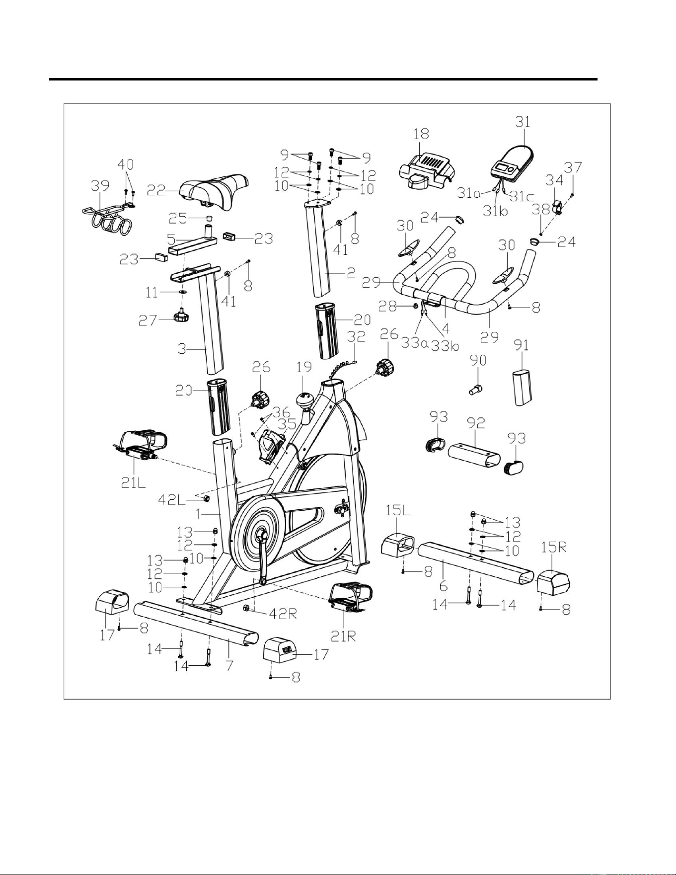
31
EXPLODED DIAGRAM (DIAGRAMA DE DESPIECE) 1
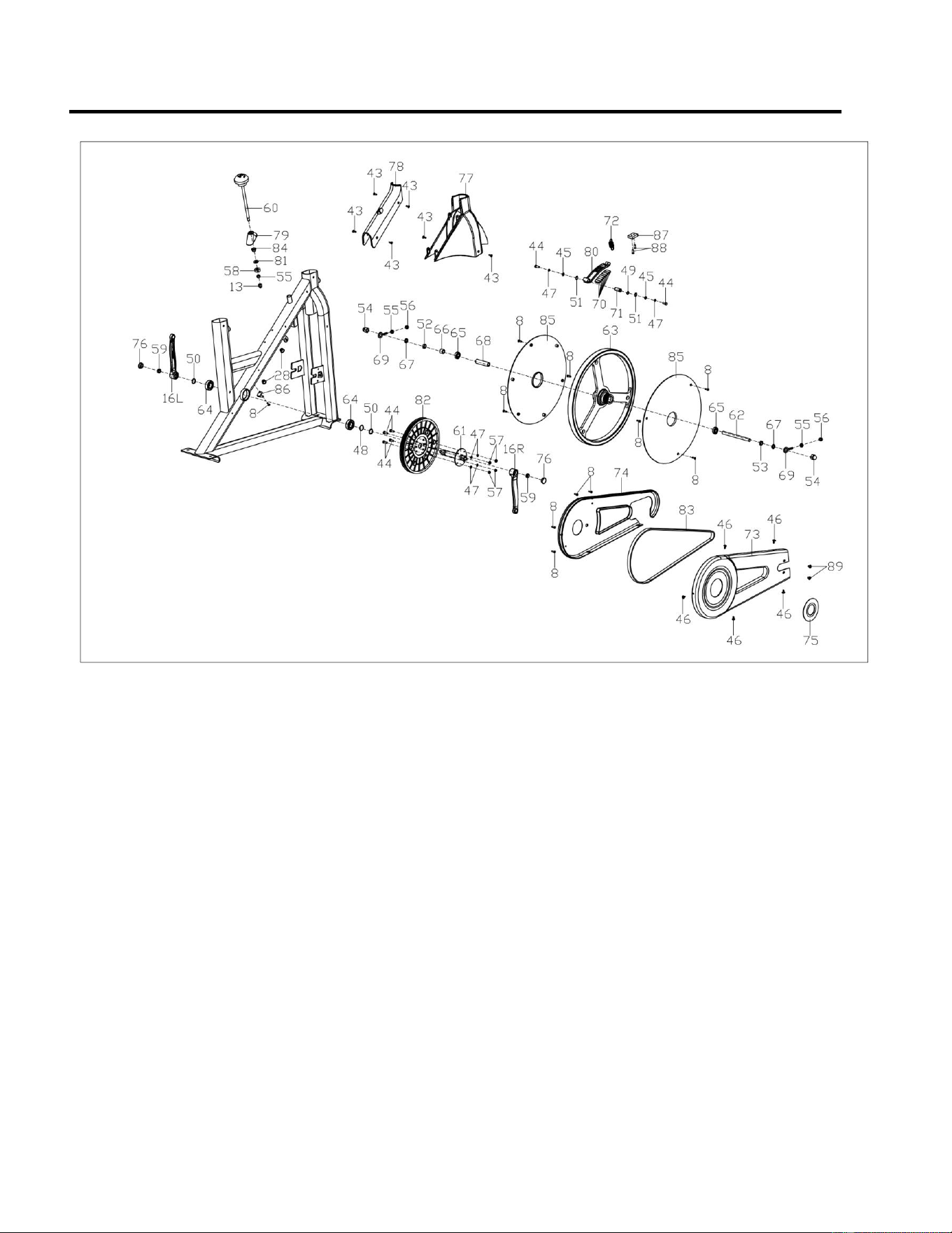
32
EXPLODED DIAGRAM (DIAGRAMA DE DESPIECE) 2
Version: 1.1

33