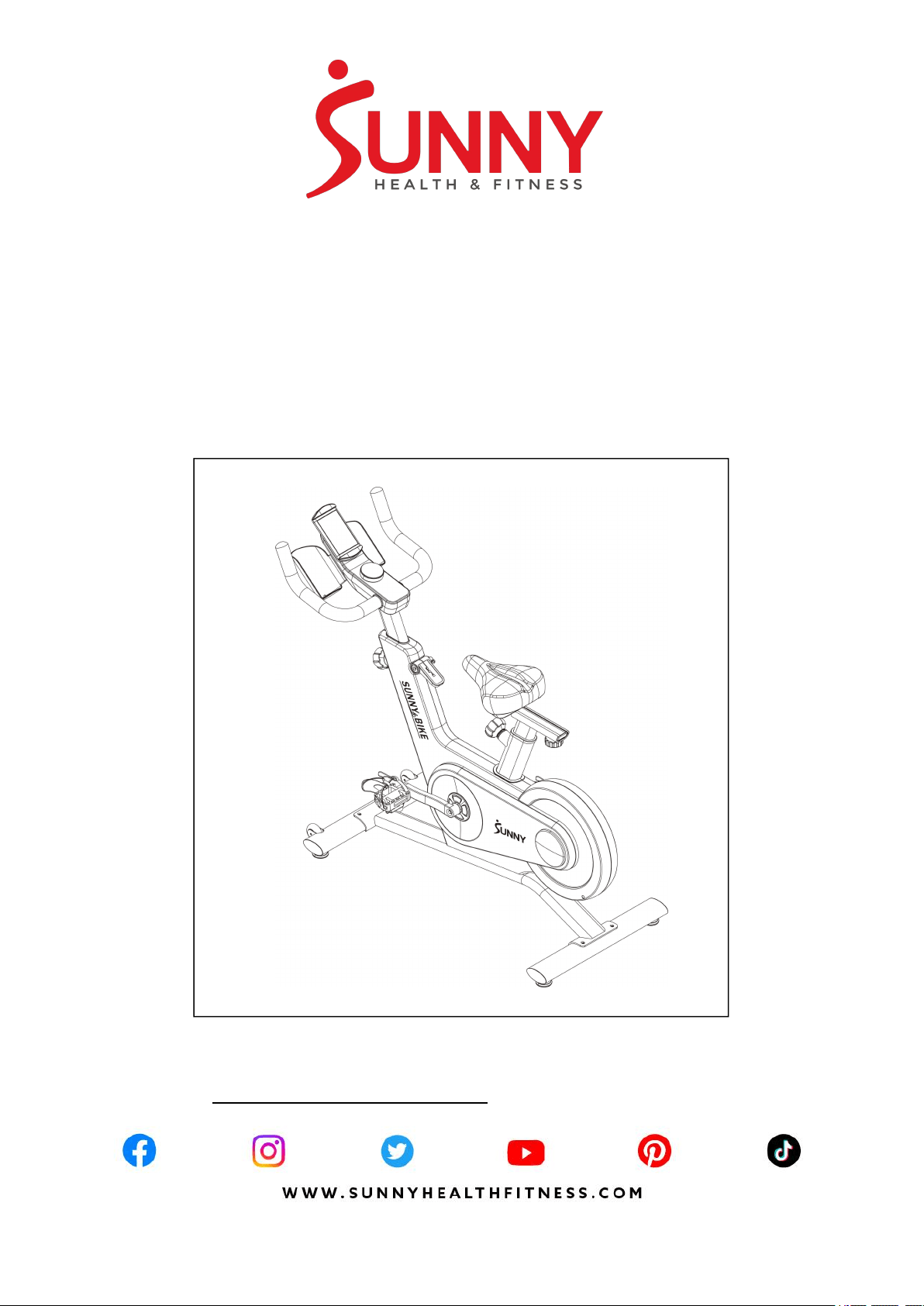
TRYDEN CONNECTED MAGNETIC
CYCLE BIKE
SF-B122049
USER MANUAL
IMPORTANT! Please retain owner’s manual for maintenance and adjustment instructions. Your
satisfaction is very important to us, PLEASE DO NOT RETURN UNTIL YOU HAVE
CONTACTED US: [email protected] or 1- 877 - 90SUNNY (877-907-8669).

1
IMPORTANT SAFETY INFORMATION
We thank you for choosing our product. To ensure your safety and health, please use this
equipment correctly. It is important to read this entire manual before assembling and using the
equipment. Safe and effective use can only be achieved if the equipment is assembled,
maintained, and used properly. It is your responsibility to ensure that all users of the equipment
are informed of all warnings and precautions.
1. Before starting any exercise program, you should consult your physician to determine if you
have any medical or physical conditions that could put your health and safety at risk or prevent
you from using the equipment properly. Your physician’s advice is essential if you are taking
medication that affects your heart rate, blood pressure, or cholesterol level.
2. Be aware of your body’s signals. Incorrect or excessive exercise can damage your health.
Stop exercising if you experience any of the following symptoms: pain, tightness in your chest,
irregular heartbeat, shortness of breath, lightheadedness, dizziness, or feelings of nausea. If
you do experience any of these conditions, you should consult your physician before
continuing with your exercise program.
3. Keep children and pets away from the equipment. The equipment is designed for adult use
only.
4. Use the equipment on a solid, flat level surface with a protective cover for your floor or carpet.
To ensure safety, the equipment should have at least 2 feet (60 CM) of free space all around it.
5. Ensure that all nuts and bolts are securely tightened before using the equipment. The safety of
the equipment can only be maintained if it is regularly examined for damage and/or wear and
tear.
6. Always use the equipment as indicated. If you find any defective components while
assembling or checking the equipment, or if you hear any unusual noises coming from the
equipment during exercise, discontinue use of the equipment immediately and do not use until
the problem has been rectified.
7. Wear suitable clothing while using the equipment. Avoid wearing loose clothing that may
become entangled in the equipment.
8. Do not place fingers or objects into the moving parts of the equipment.
9. The maximum weight capacity of this unit is 245 pounds (110 KG).
10. The equipment is not suitable for therapeutic use.
11. To avoid bodily injury and/or damage to the product or property, proper lifting and moving are
required.
12. Your product is intended for use in cool and dry conditions. You should avoid storage in
extreme cold, hot or damp areas as this may lead to corrosion and other related problems.
13. This equipment is designed for indoor and home use only; it is not intended for commercial
use.
3
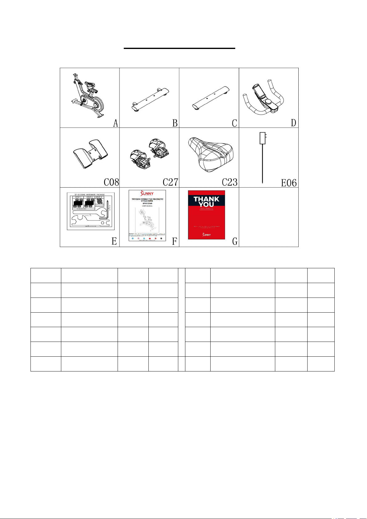
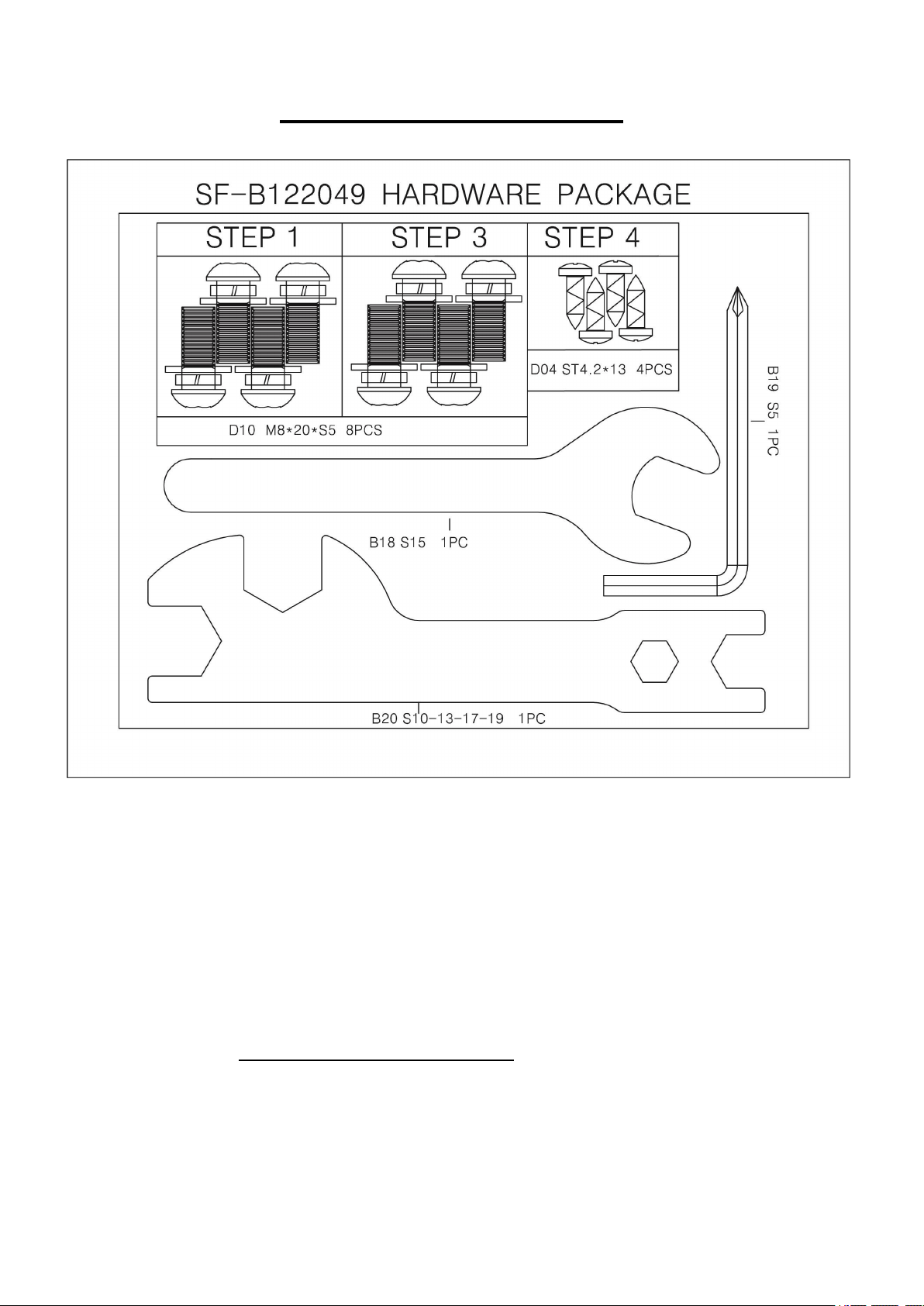
HARDWARE PACKAGE
Ordering Replacement Parts (U.S. and Canadian Customers only)
Please provide the following information in order for us to accurately identify the part(s) needed:
The model number (found on cover of manual)
The product name (found on cover of manual)
The part number found on the “EXPLODED DIAGRAM” and “PARTS LIST” (found near the
end of the manual)
4
ASSEMBLY INSTRUCTIONS
We value your experience using Sunny Health and Fitness products. For assistance with parts
(877- 907-8669).
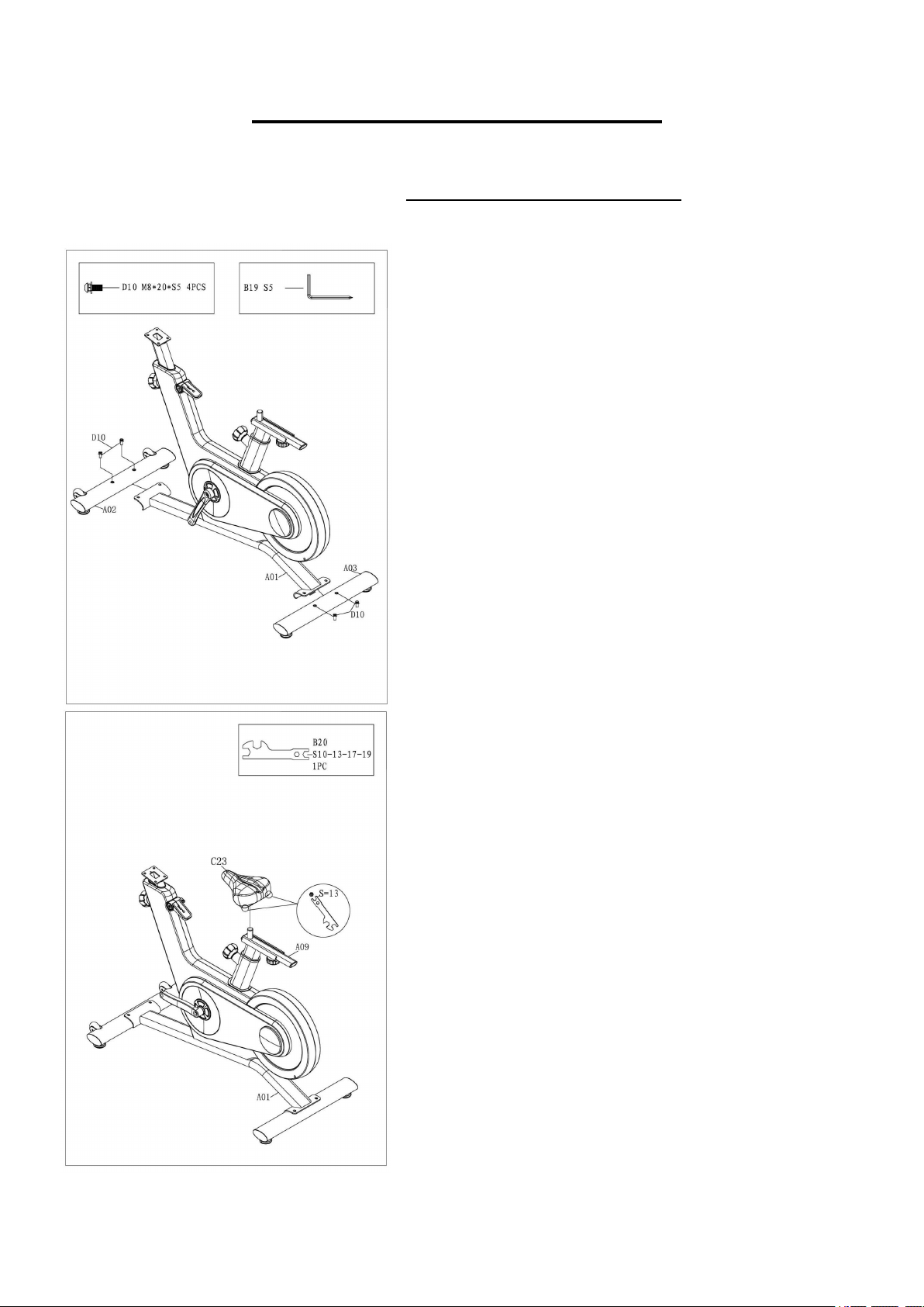
STEP 1:
Attach the Front & Rear Stabilizers (No. A02 & No.
A03) to the Main Frame (No. A01) by using 4 Bolts
(No. D10). Tighten and secure with Allen Wrench
(No. B19).
STEP 2:
Secure Seat (No. C23) to Seat Slider Tube (No. A09)
with Spanner (No. B20).
5
We value your experience using Sunny Health and Fitness products. For assistance with parts
(877- 907-8669).
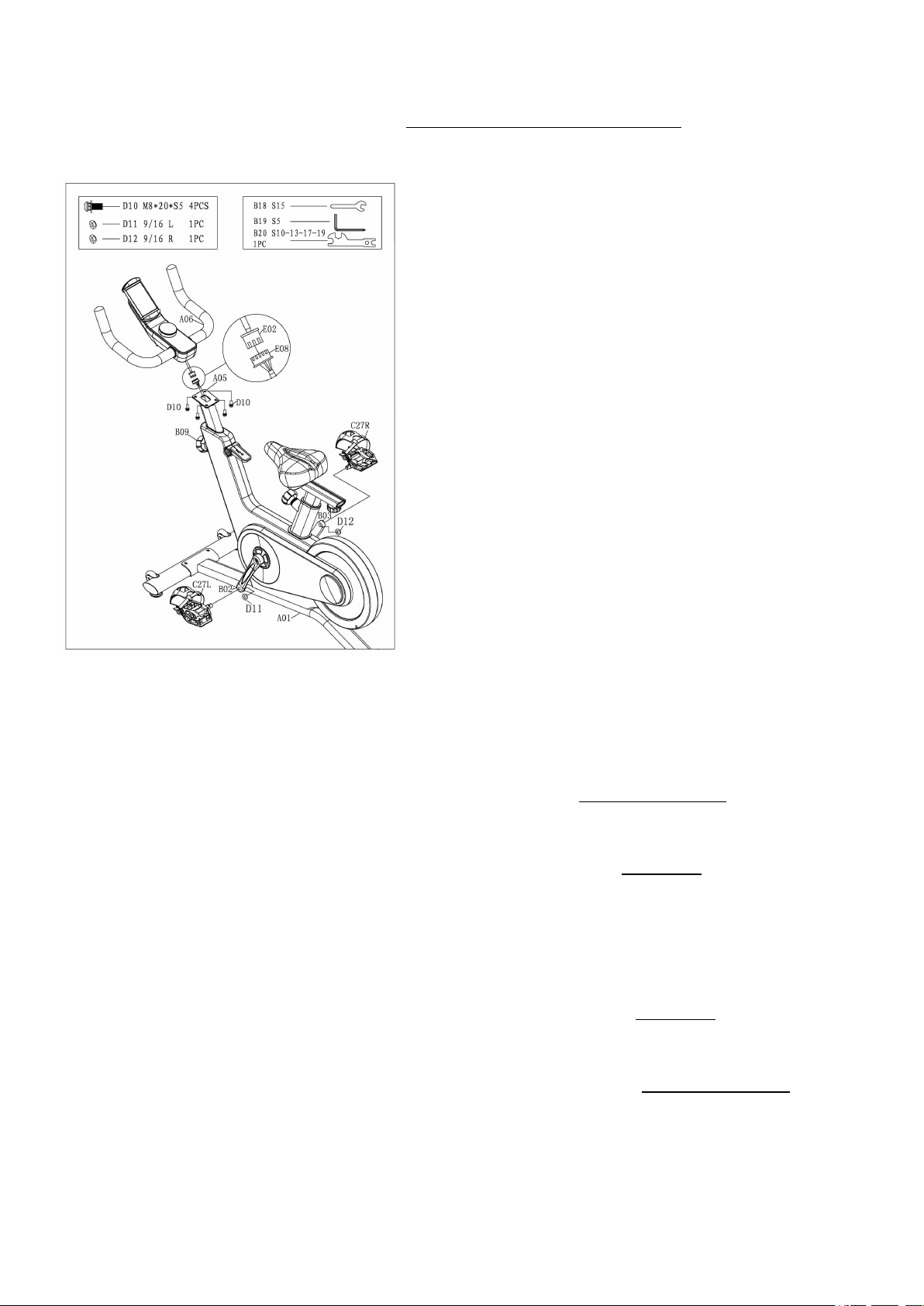
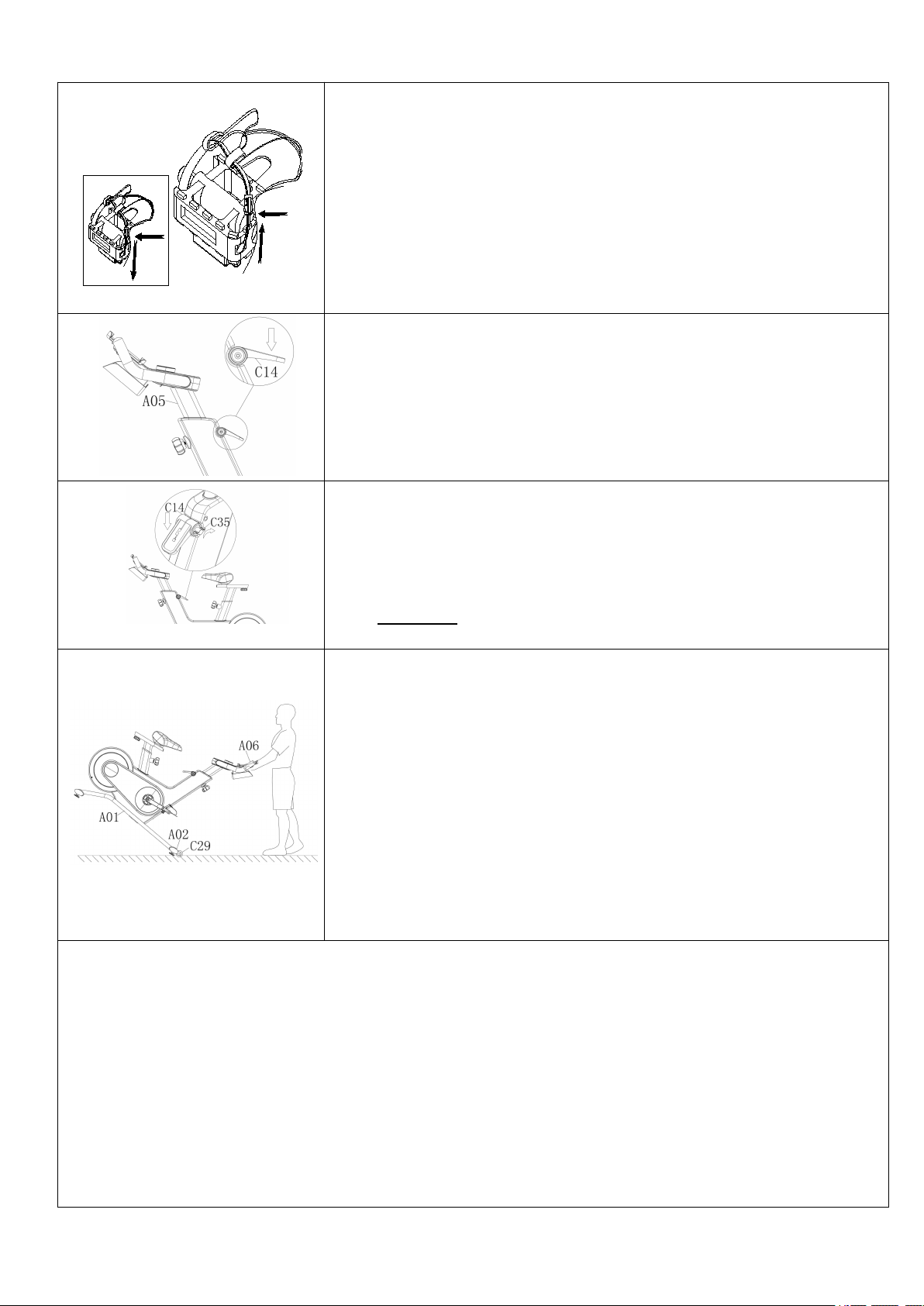
STEP 3:
WARNING! Read instructions carefully as improper
assembly may cause permanent damage to your
bike.
Loosen and pull the Circular Knob (No. B09)
outward. Raise the Upright Tube (No. A05) and pay
attention to the protection of Middle Single Wire
(No. E08) to avoid falling into the tube. Connect the
Top Single Wire (No. E02) with the Middle Single
Wire (No. E08).
Attach Handlebar (No. A06) onto the Upright Tube
(No. A05) by using 4 Bolts (No. D10). Tighten and
secure with Allen Wrench (No. B19).
Remove the Nylon Nut L&R (No. D11 & D12)
located on the Pedal Set L/R (No. C27L/R). The
Nylon Nut L (No. D11) is blue on the inside. The
Nylon Nut R (No. D12) is white on the inside. The
Pedal Set L/R (No. C27L/R) are labeled L and R.
Align the Left Pedal Set L (No. C27L) with the Left
Crank Arm (No. B02) at 90°. Screw the Left Pedal
Set L (No. C27L) counter-clockwise into Left Crank
Arm (No. B02). Once screwed in place, use the
Spanner (No. B18) to tighten securely. Then screw
Nylon Nut L (No. D11) clockwise into the thread end
of the Left Pedal Set L (No. C27L). Secure with
Spanner (No. B18 & B20).
Align the Right Pedal Set R (No. C27R) with the
Right Crank Arm (No. B03) at 90°. Screw the Right
Pedal Set R (No. C27R) clockwise into Right Crank
Arm (No. B03). Once screwed in place, use the
Spanner (No. B18) to tighten securely. Then screw
Nylon Nut R (No. D12) counter-clockwise into the
thread end of the Right Pedal Set R (No. C27R).
Secure with Spanner (No. B18 & B20).
6
We value your experience using Sunny Health and Fitness products. For assistance with parts
(877- 907-8669).
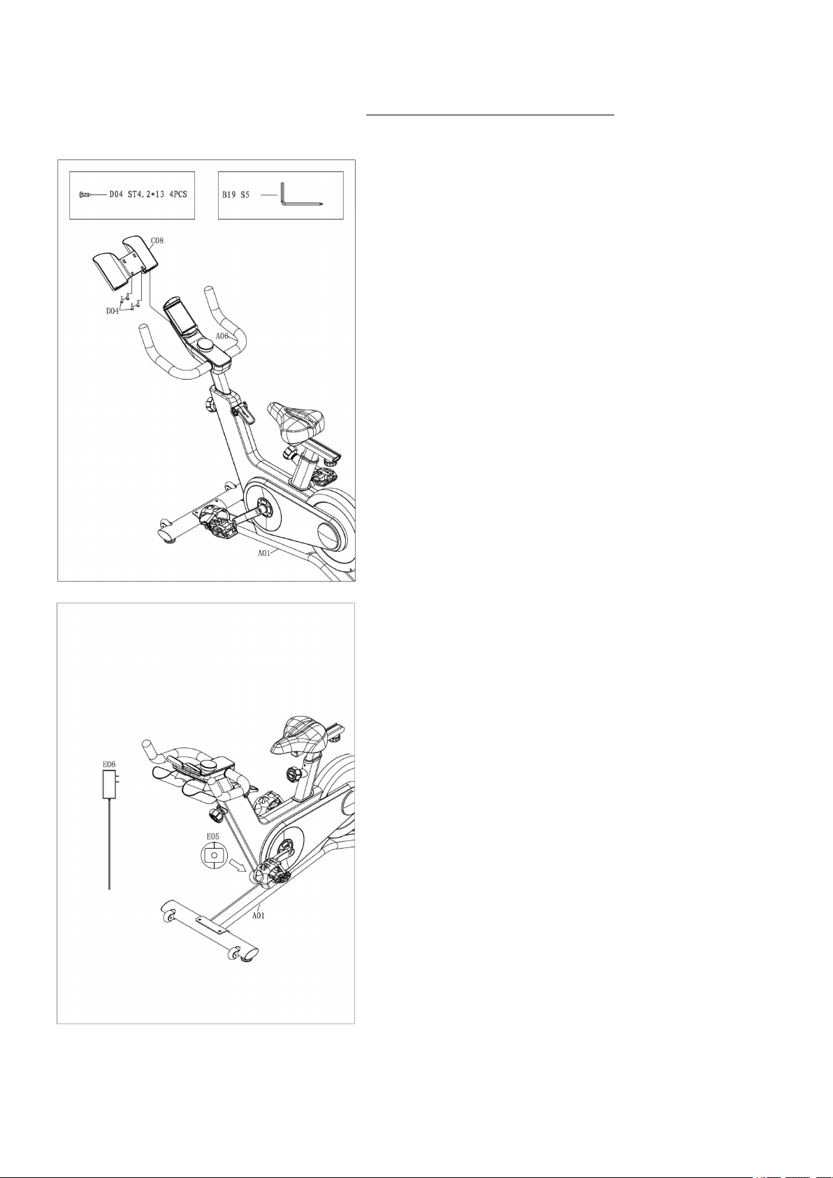
STEP 4:
Attach the Bottle Holder (No. C08) to the
Handlebar (No. A06) by using the 4 Screws (No.
D04). Tighten and secure with Allen Wrench (No.
B19).
STEP 5:
Insert the Power Adapter (No. E06) into the
Power Wire (No. E05) .
The assembly is complete!
7
ADJUSTMENTS & USAGE GUIDE
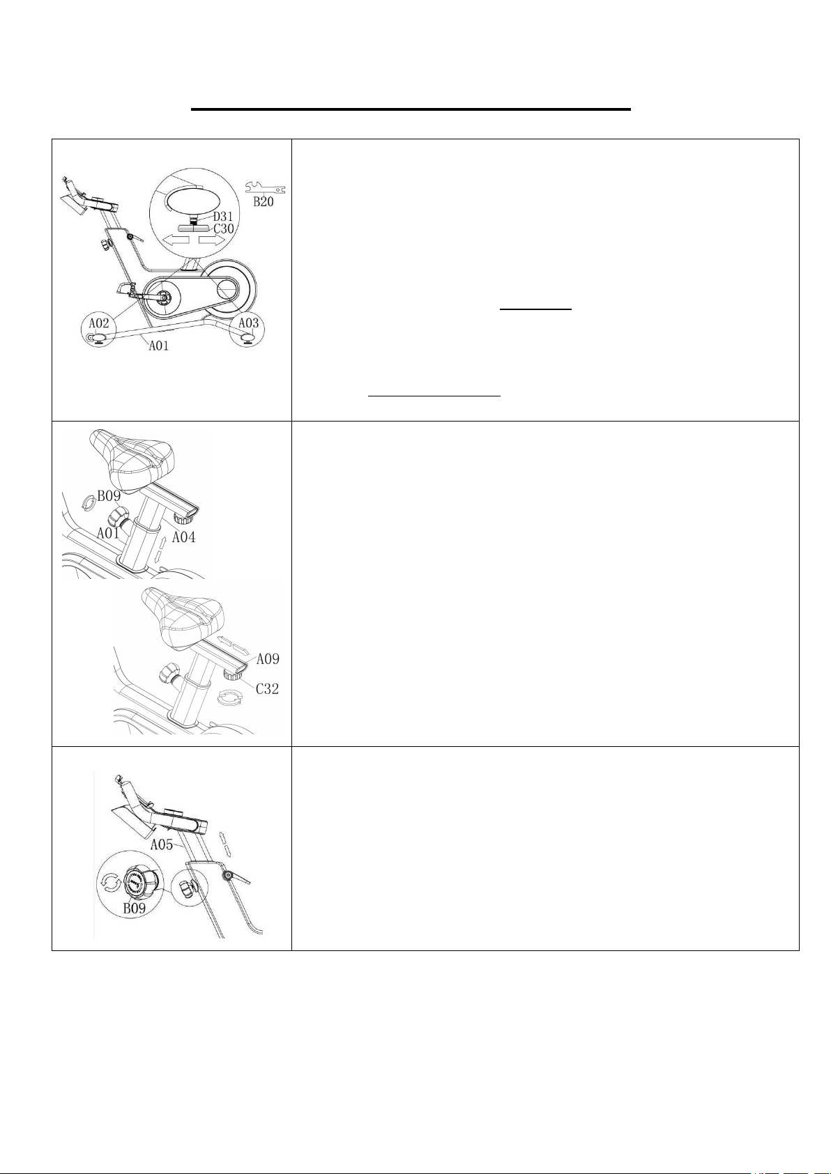
ADJUSTING THE BALANCE
In order to achieve a smooth and comfortable ride, you must
ensure that the stability of the bike is secured. If you notice that the
bike is unbalanced during use, you should adjust the 4 Foot Pads
(No. C30) located beneath the Front & Rear Stabilizers (No. A02
& No. A03) of the bike. To do so, use Spanner (No. B20) to loosen
Nut (No. D31) by turning it clockwise. With the nut loosened, rotate
the Foot Pads (No. C30) until it sits level with the surface that the
bike is on. When you have finished adjusting the Foot Pads (No.
C30), use Spanner (No. B20) to re-tighten the Nut (No. D31) by
turning it counter-clockwise.
ADJUSTING THE SEAT
The seat of this bike is fully adjustable as it moves Up, Down, Fore
(forward), Aft (backward).
To adjust the height of the Seat Post (No. A04), loosen and pull
the Circular Knob (No. B09) outward, then raise or lower the seat
to the desired height. Once adjusted, re-insert and tighten the
Circular Knob (No. B09) to secure the seat in place.
To adjust the seat back and forth, loosen the Seat Knob (No. C32)
outward, then slide the Seat Slider Tube (No. A09) to the desired
position. Once positioned, re-tighten the Seat Knob (No. C32) to
secure the seat slider tube in place.
ADJUSTING THE HANDLEBAR
It is important that the handlebar and seat are both set to the
correct height to your body. To adjust the handlebar height, loosen
and pull the Circular Knob (No. B09) outward, then slide the
Upright Tube (No. A05) up or down to the desired height. Once
adjusted, re-insert and tighten the Circular Knob (No. B09) to
secure the handlebar in place.
8
PEDAL STRAP ADJUSTMENT
Your feet should be secured in the toe clips during exercise. Place
your feet as far forward into the toe clips as you can. With your feet
in place, turn the crank to bring one foot to within arm’s reach,
grasp the pedal strap and pull it upward to tighten the toe clip cage.
Then insert the strap back into the hoop of the toe clip. Repeat this
process to secure your other foot.
EMERGENCY BRAKE
During use, users can stop the bike completely by pushing down
on the Brake Handle (No. C14). Pushing down on the Brake
Handle (No. C14) will enforce the brake and bring the bike to an
immediate stop.
Child Safety Lock
When you finish exercising, users can use the Child Safety Lock
(No. C35) to stop the bike from moving. Pressing down the Brake
Handle (No. C14) and then tighten the Child Safety Lock (No.
C35) clockwise.
TRANSPORTING THE BIKE
To move the bike, stand at the front of the bike so that you’re
directly in front of the handlebar. Firmly grasp and hold each side of
the handlebar, place one foot on the Front Stabilizer (No. A02)
and tilt the bike towards you until the 2 Transportation Wheels
(No. C29) touch the ground. With the Transportation Wheels (No.
C29) on the ground, you can transport the bike to the desired
location with ease.
NOTE: When moving the bike, always use caution as unexpected
impact, such as dropping the bike, may cause injury and affect the
bike’s operation.
DISMOUNTING WARNING:
For your safety, it is recommended that you never attempt to dismount or remove your feet from the
pedals until both the flywheel and pedals/cranks have come to a complete stop. Failure to follow
this recommendation may lead to loss of control and/or serious injury.
Here are a few examples of how to safely dismount the bike:
1. Reduce the pedal speed until the pedals/crank come to a complete stop.
2. Increase the resistance until the pedals/crank come to a complete stop.
3. Push and hold the Brake Handle (No. C14) down until the pedals/crank come to a complete
stop.
9
IMPORTANT ELECTRICAL INFORMATION
WARNING: This bike requires a power source of 1 amp (100-240V) in order to properly
operate. For your safety, as well as the safety of others, please verify that the power source is
correct before plugging in the equipment. Any power source above or below this level could
cause significant damage to the equipment and or user.
EXERCISE CONSOLE
FUNCTION BUTTONS:
Display Switch Button:
Short press the Console (No. E01) to change the display mode;
Long press the Console (No. E01) for 3 seconds to reset all value to zero.
Adjust the resistance:
Turn the Console (No. E01) clockwise, increase the resistance value from 1 to 16.
Turn the Console (No. E01) counter-clockwise: reduce the resistance value from 16 to 1.
When adjusting the resistance, console will display resistance value.
When staying on the resistance value, short press the Console (No. E01) to show other
display.
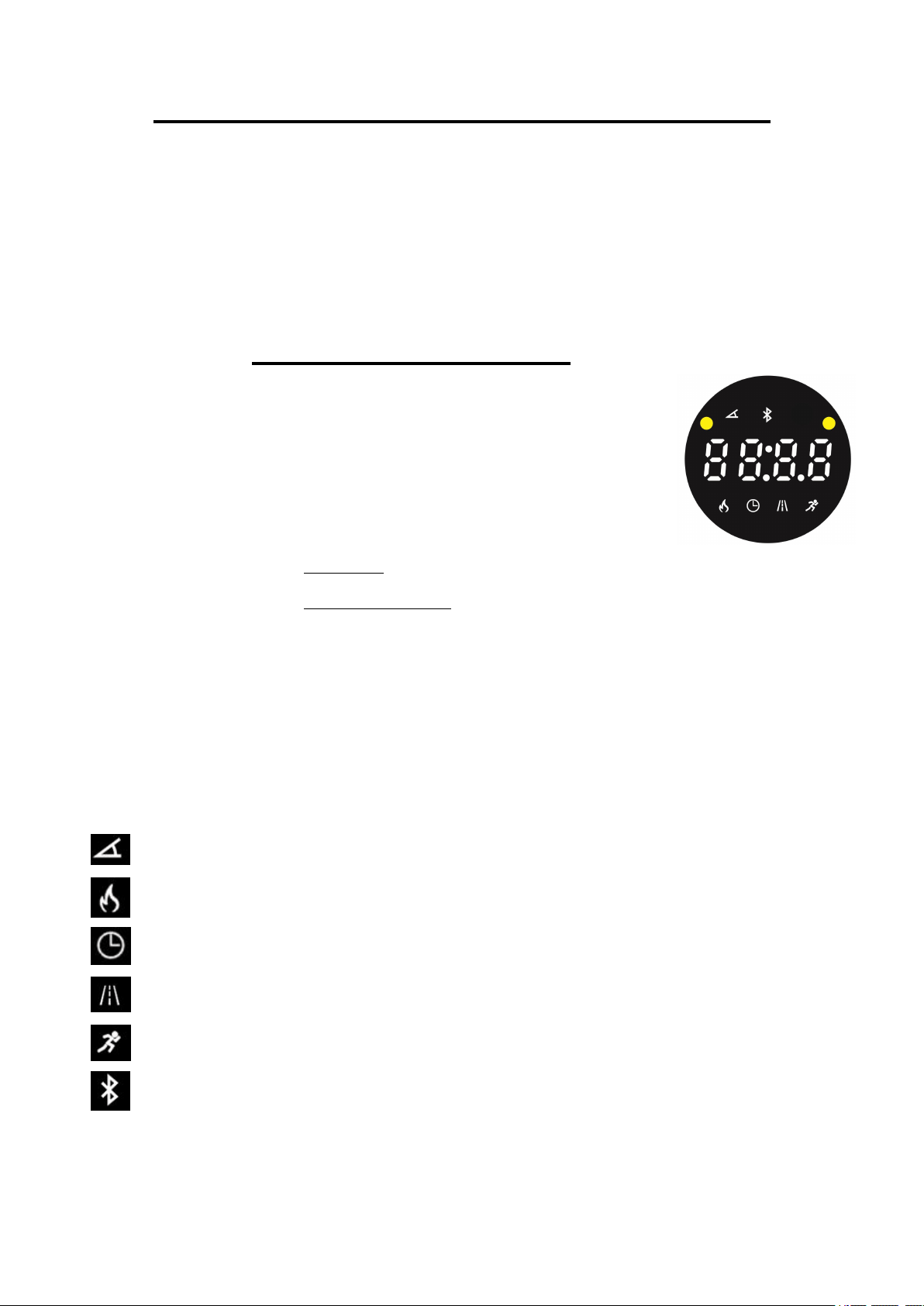
FUNCTIONS:
Display: Cycles through all Functions: Calories-Time-Distance-Speed-Resistance.
1. : Display current resistance “1,2,3,…,16”.
2. :Display the calories has consumed. Accumulate total calories from 0.0 to 999.9.
3. : Display the time has run. Accumulates total time from 00:00 to 99:59.
4. : Display the distance has run. Accumulates total distance from 0.0 to 99.9 Miles.
5. : Display current speed from 0.0 to 72.0 MPH.
6. : When connected with Bluetooth, Display Bluetooth connected.

10
APP CONNECTION:
1. Scan the QR code below to download the SunnyFit app onto your mobile device.
2. If this is your first time using the SunnyFit app, follow the in-app instructions to register for
your free SunnyFit account and log in.
3. Ensure that the Bluetooth
function is turned on from your mobile
device.
4. To connect the equipment to the SunnyFit app:
a) From the “Workout” tab, press on the “Search” button to search for your equipment.
b) Once your equipment appears on the list, tap the “Select” button to confirm.
c) Note: If your equipment does not appear on the "Searching for Equipment" list, check
the CONSOLE on your equipment to ensure that it is not in sleep mode and your
phone's Bluetooth function is on, then tap "Retry" to search again.
d) Once your equipment shows up on the “Workout” tab as “Currently Selected”, your
equipment is now ready to display, track, and record your equipment’s workout stats
on the app!
5. If you are unable to replicate these steps, or have any other issues with the SunnyFit app,
please contact SunnyFit support at support@sunnyfit.com, or use the in-app “Contact Us”
form to request support (“Me” tab -> “Contact Us”).

11
MAINTENANCE INSTRUCTIONS
This is general information for daily, weekly and monthly maintenance to be performed on your
bike.
DAILY MAINTENANCE
After each exercise session, wipe down all the
equipment: seat, frame, and handlebars. Pay
special attention to the seat post, handlebar
post, and belt/chain guard. Sweat is very
corrosive and may cause problems that require
parts replacement later.
1. Get on the bike and engage the drive train.
2. Pay attention to any vibrations felt through
the pedals. If you feel any vibrations, you
may need to tighten the pedals, bottom
bracket, or adjust the drive belt/chain
tension.
3. Use a wrench to tighten the pedals until
they are secure.
MONTHLY MAINTENANCE
1. Check if all hardware is secure, such as: water
bottle holder, flywheel nuts, belt/chain guard
bolts, brake caliper lock nuts and brake caliper
tension rod nuts.
2. Inspect the brake tension rod for signs of wear
such as missing threads. Clean and lubricate
the brake tension rod.
3. Clean and lubricate the seat post, handlebar
post and seat slider. Remove any buildup of
foreign material.
WEEKLY MAINTENANCE
1. Inspect moving parts and tighten the
hardware.
2. Inspect pull pin frame fittings to make sure
the fittings are secured. Loose frame fittings
may strip out threads over time and cause
extensive damage.
3. Clean and lubricate pop pin assemblies.
Pull on the pin and spray a small amount of
lubricant onto the shaft.
4. Tighten the seat hardware to make sure the
seat is level and centered.
5. Brush and treat the resistance pads.
Remove any foreign material that may have
collected on the pads. Spray the pads with
silicone lubricant. This helps to reduce
noise from friction between the pads and
the flywheel.
6. Visually inspect the bottom bracket, toe
clips and toe straps. If any of them are
loose or disconnected, attach and tighten.
LEATHER BRAKE PAD CARE (IF Applicable)
1. Perform this maintenance when the brake pad
is first installed and for the life of the brake
pad. Following these simple guidelines can
increase the life of your brake pads.
2. Some brake pad assemblies are
pre-lubricated. Squeeze the brake pad. If
lubricant is released, then the pad has been
pre-lubricated.
3. If the brake pad is dry, then coat the brake pad
with 3-n-1 oil. Brush the leather with a clean,
wire bristle brush, and then apply the oil. The
oil should be allowed to soak into the pad.
Repeat 4-5 times until the pad is saturated, but
not dripping with oil. When the pad is
saturated, it will no longer absorb oil.
4. Inspect the brake pad weekly and lubricate if
needed. The pad should not have a glazed
appearance. If the pad appears glazed, then
brush it with wire brush and apply lubricant as
needed. If any of the sponge padding is
showing through the leather pad, the brake
pad should be replaced.
NOTE: If you are unable to resolve an issue using the troubleshooting guide above, please
contact Customer Service at support@sunnyhealthfitness.com.
12
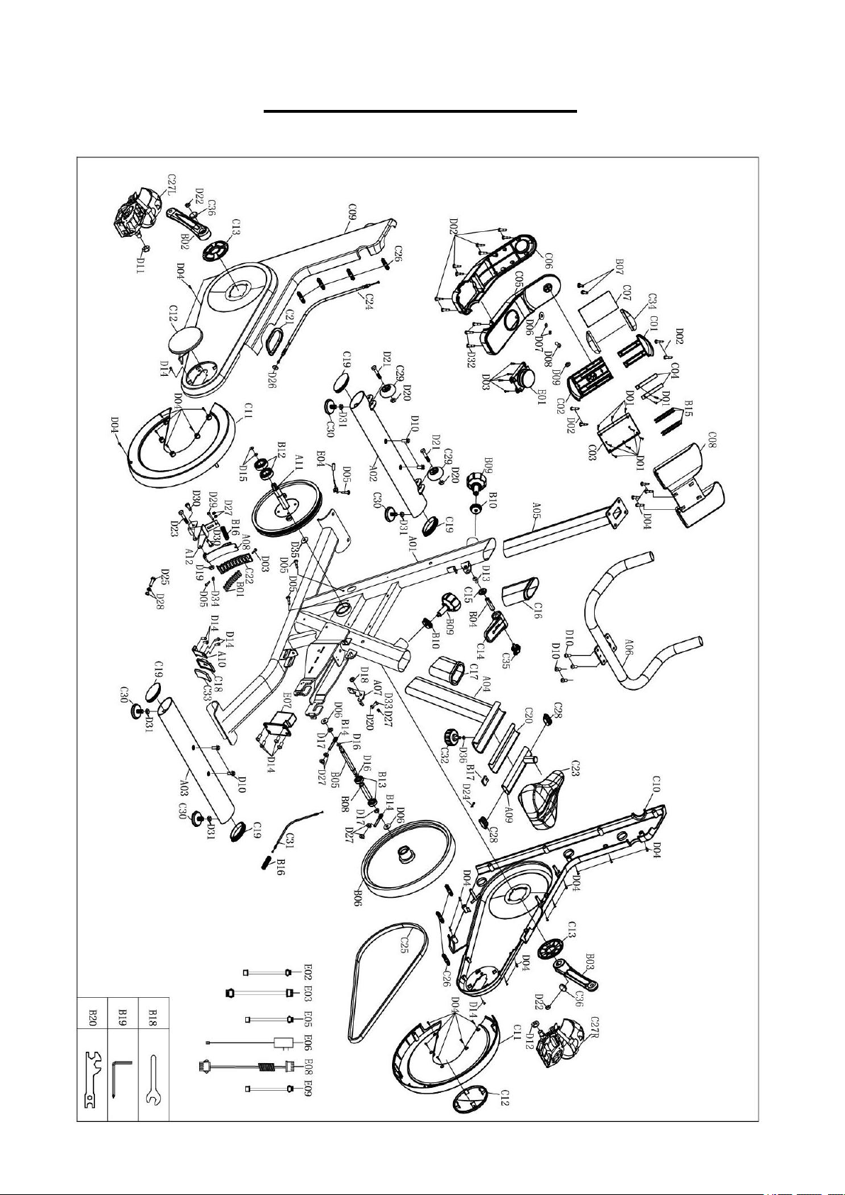
EXPLODED DIAGRAM

13
PARTS LIST
No.
Description
Spec.
Qty.
No.
Description
Spec.
Qty.
A01
Main Frame
1
C10
Right Chain Cover
1
A02
Front Stabilizer
1
C11
Big Flywheel Cover
2
A03
Rear Stabilizer
1
C12
Small Flywheel Cover
2
A04
Seat Post
1
C13
Crank Cover
2
A05
Upright Tube
1
C14
Brake Handle
1
A06
Handlebar
1
C15
Brake Handle Cover
1
A07
Brake Plate
1
C16
Upright Sleeve
1
A08
Magnetic Plate
1
C17
Seat Sleeve
1
A09
Seat Slider Tube
1
C18
Wolly Felt Bracket
1
A10
Spring Plate
1
C19
Oval Plug
4
A11
Belt Pulley
1
C20
Seat Bushing
1
A12
Adjusted Plate
1
C21
Rubber Ring
1
B01
Magnet
8
C22
Magnet Bracket
1
B02
Left Crank Arm
1
C23
Seat
1
B03
Right Crank Arm
1
C24
Brake Cable
1
B04
D-Shape Fixed Axis
1
C25
Belt
1
B05
Flywheel Spindle
1
C26
Plastic Button
7
B06
Flywheel
1
C27L/R
Pedal Set L/R
2
B07
Ball Plug
2
C28
Oval Pad
2
B08
Bearing Sleeve
1
C29
Transportation Wheel
2
B09
Circular Knob
2
C30
Foot Pad
4
B10
Knob Nut
2
C31
Motor Cable
1
B11
Knob Plate
2
C32
Seat Knob
1
B12
Bearing
6203-ZZ
2
C33
Wolly Felt
1
B13
Bearing
6001-2RS
2
C34
Rubber Plate
2
B14
Tighten Bolt
2
C35
Child Safety Lock
1
B15
Tension Spring
4
C36
Crank Cover
2
B16
Brake Spring
2
D01
Screw
ST2.2*6.5
10
B17
Seat Slider Plate
1
D02
Screw
ST2.9*7
12
B18
Spanner
S15
1
D03
Screw
ST3.5*10
5
B19
Allen Wrench
S5
1
D04
Screw
ST4.2*13
26
B20
Spanner
S10-13-17-19
1
D05
Screw
ST4.2*12
4
C01
Device Holder Upper Plate
1
D06
Big Flat Washer
Φ8*Φ20*1.5
3
C02
Device Holder Lower Plate
1
D07
Big Flat Washer
Φ5*Φ10*1.5
2
C03
Device Holder
1
D08
Bolt
M5*15
1
C04
Plastic Support Plate
2
D09
Nut
M5
1
C05
Console Top Cover
1
D10
Bolt
M8*20*S5
8
C06
Console Bottom Cover
1
D11
Nylon Nut L
9/16 L
1
C07
Silicone Pad
1
D12
Nylon Nut R
9/16 R
1
C08
Bottle Holder
1
D13
Bolt
M6*12
1
C09
Left Chain Cover
1
D14
Bolt
M5*10
10

14
No.
Description
Spec.
Qty.
No.
Description
Spec.
Qty.
D15
Spring Washer
Φ17
2
D31
Nut
M10
4
D16
Spring Washer
Φ12
2
D32
Screw
ST4.2*12
3
D17
Nut
M10*1
2
D33
Bolt
M6*25
1
D18
Nut
M8*H7
1
D34
Flat Washer
Φ4*Φ8*1.5
1
D19
Nut
M6
1
D35
Wave spring washer
Φ21xΦ17.5x0.3t
1
D20
Nut
M6
3
D36
Big Flat Washer
Φ8*Φ20*1.5
1
D21
Bolt
M6*32*S5
2
E01
Console
1
D22
Bolt
M10*1.25
2
E02
Top Signal Wire
L=150mm
1
D23
Bolt
M6*45
1
E03
Bottom Signal Wire
L=260mm
1
D24
Pin
1.2*20
1
E04
Sensor
1
D25
Bolt
M8*30*S6
1
E05
Power Wire
L=150mm
1
D26
Flat Washer
Φ6*Φ18*1.5
1
E06
Power Adapter
L=1900mm
1
D27
Nut
M6
7
E07
Motor
1
D28
Nut
M8
2
E08
Middle Signal Wire
L=800mm
1
D29
Bolt
M6*45
1
E09
Bluetooth Wire
L=150mm
1
D30
Bolt
M8*16*S6
2
Version:
1
1.