Loading ...
Loading ...
Loading ...

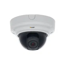
AXIS P3364–V
Hardware Overview
Network connector - RJ-45 Ethernet connector. Supports P ower over Ethernet (PoE).
NOTICE
Due to local reg ulations or the environmental a nd electrical conditions in which the product is to be used, a shielded
network cable (STP) may be appropriate or required. Any network cables that are routed in outdoor environments or similar
shall be shielded (STP) and intended for their specific use. Make sure that the network switch is properly grounded. See
Electromagnetic Co m patibility (EMC)
for regulatory requirements.
Audio in (pink) - 3.5 mm input for a m ono microphone, or a line-in m ono signal (left channel is used from a stereo signal).
Audio out (green) - 3.5 mm output for audio (line level) that can be connected to a pub lic address (PA) system o r an active speaker
with a built-in a m p lifier. A stereo connector must be used for audio out.
SD card slot - A standard or high-capacity SD card (not included) can be used for local recording with removable storage.
NOTICE
To prevent corruption of recordings, the SD card should be unmounted before removal. To unmount, go to Setup > System
Options > Storage > SD Card and click Unmount.
Control button - The control button is used for:
• ConnectingtoanAXISVideoHostingSystemservice.See
page 42
. To connect, press and hold the button for about
1 second until the Status LED flashes green.
• ConnectingtoAXISInternetDynamicDNSService. See
page 43
. To connect, press and hold the button for
about 3 seconds.
• Resetting the p rod uct to factory default settings. See
page 49
.
I/O terminal connector - Use in applications for e.g . motion dete c tion, event triggering, time lapse recording and alarm notifications.
In addition to an auxili ary pow e r and a GND pin, the I/O terminal connector pro vides the interface to:
• Digital output — For connecting external devices such as relays and LEDs. Connecte
d devices can be activated by
the VAPIX® Application Programming Interface, output b uttons on the Live View page or by an Action Rule. The
output will show as active (shown under System Options > Ports & Devices) if the alarm device is activated.
• Digital input — An alarm input for conne cting devices that can toggle between an open and closed circuit, for
example: PIRs, door/w indow contacts, glass break
detectors, etc. When a signal is received the state changes and
the input becomes active (shown under System Options > Ports & Devices).
LED Indicators
LED
Color
Indication
Green
Steady for connection t
o a 100 MBit/s network. Flashes for network activity.
Amber
Steady for connection to a 10 MBit/s network. Flashes for network activity.
Network
Unlit No network connection.
Green Steady g reen for normal operation.
Amber
Steady during startup and when restoring settings.
Status
Red
Slow flash for failed upgrade.
Green
Normal operation.
Power
Amber
Flashes green/amber during firmware upgrade.
5
Loading ...
Loading ...
Loading ...