Hangzhou Hikvision Digital Technology CO.,Ltd. No.555 Qianmo Road, Binjiang District, Hangzhou 310052, China
E N G L I S H
1
2
Specication
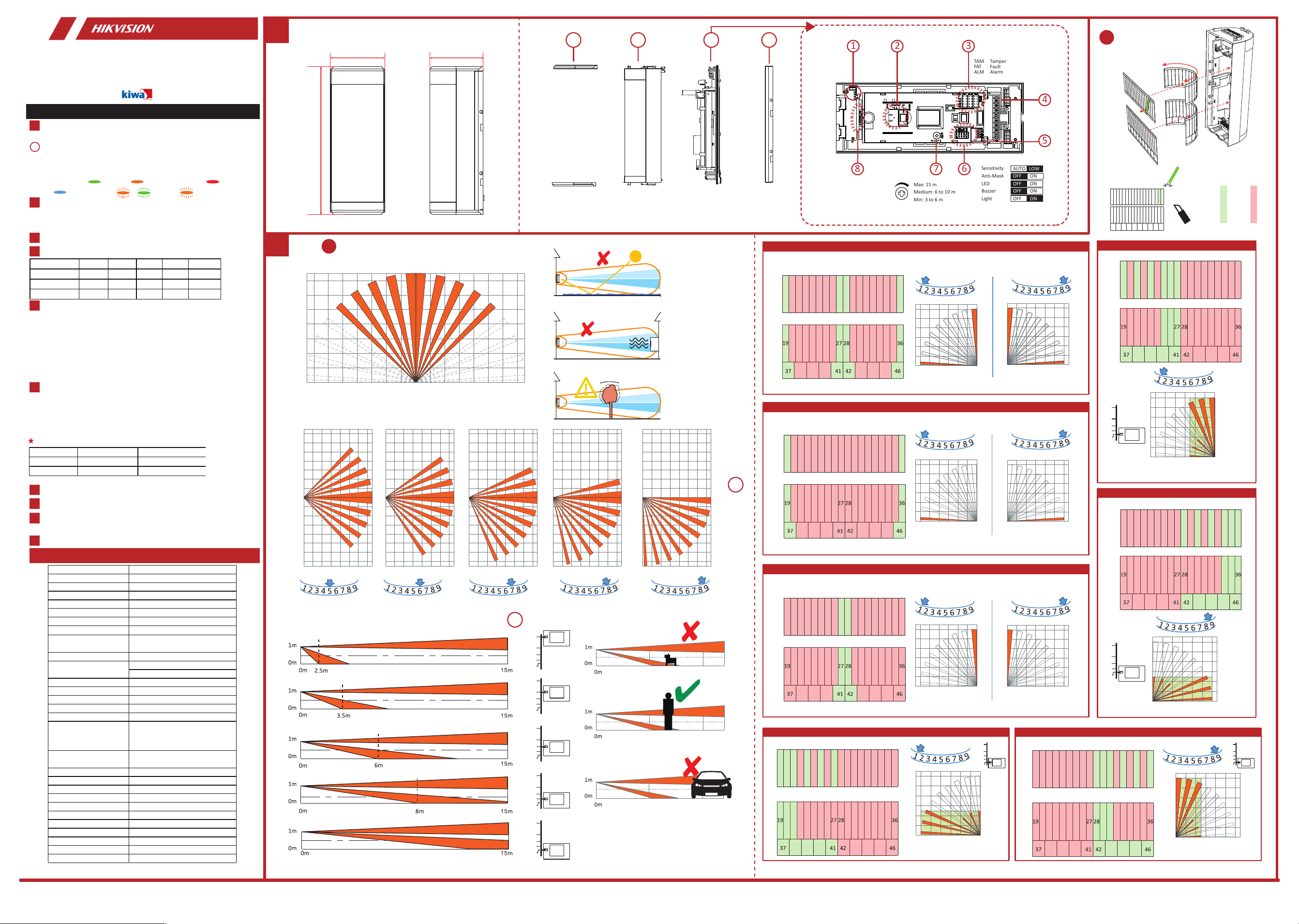
Appearance
1. Top/Bottom Cover
a. Tamper Resistance: 1K, 2K2, 4K7, 5K6, 6K8
b. Alarm Resistance: 1K, 2K2, 4K7, 5K6, 6K8
c. Fault Resistance: 1K, 2K2, 4K7, 5K6, 6K8
a. Normally Closed
Note: The resistor must be connected in series with one end of the detector.
d. Triple End of Line Wiring
b. Single End of Line Wiring
c. Double End of Line Wiring
Powering On
Normal Open Terminal
Lighting
1
Anti-masking
Installation
Detection Range
Wired Triple Signal Detector
DS-PDTT15AM-LM
User Manual
1
Ⅰ
Ⅱ
1
2
2 3 4
2. Front Panel
3. PCBA
3
The Main Printed Circuit Board Assembly (PCBA)
1. Tamper Switch 2. Bottom PIR Sensor 3. EOL Resistance
Ⅰ. Detection range
1. PIR Angle 2. PIR Distance
Ⅱ. Masking seal
5. Normal Open Terminal 6. DIP Switch4. Terminal
Masking Seal 1
Masking Seal 5
Masking Seal 6
Masking Seal 2
Masking Seal 3
Masking Seal 4 Masking Seal 7
Resistor Wiring
Connection Type
Method 1: Use the jumper to select EOL (End of Line) resistance on
TAMPER/ALARM/FAULT pins.
Method 2: Add the resistor to TAMPER/ALARM/FAULT wiring ports.
Note: If EOL wiring is not used, leave the jumpers OFF. Do not force the
jumper if it is not matched the pin. Method 1 & 2 should not be used on the
ALARM/TAMPER/FAULT at the same time.
2
3
4
5
6
7
10
9
8
UD27186B-A
4. Rear Panel
7. Microwave Potentiometer
8. PIR Angle
Relay Status
Normal Alarm Fault Mask Tamper
Alarm Relay Close Open Close Open Close
Fault Relay Close Close Open Open Close
Tamper Relay Close Close Close Close Open
A
B
C
D
E
A
B
C
D
E
A
B
C
D
E
A
B
C
D
E
A
B
C
D
E
A
B
C
D
E
A
B
C
D
E
A
B
C
D
E
A
B
C
D
E
15m
15m
15m
0m
0m
0m
4m4m
4m
4m
4m
8m8m
8m
8m
8m
12m12m
12m
12m
12m
15m15m
15m
15m
15m
Cut #1, #9, #19, #27, #37, #41 Cut #10, #18, #28 #36, #42, #46
1 2 3 4 5 6 7 8 9 1011 12 1314 151617 18
Masking Seal 1 top
Masking Seal 1 bottom
20212223 2425 26 293031 3233 3435
38 39 40 43 44 45
Cut #1, #19, #37 Cut #18, #36, #46
1 2 3 4 5 6 7 8 9 1011 12 1314 151617 18
Masking Seal 2 top
Masking Seal 2 bottom
20212223 2425 26 293031 3233 3435
38 39 40 43 44 45
Cut #9, #27, #41 Cut #10, #28, #42
1 2 3 4 5 6 7 8 9 1011 12 1314 151617 18
Masking Seal 3 top
Masking Seal 3 bottom
20212223 2425 26 293031 3233 3435
38 39 40 43 44 45
Cut #1, #2, #3, #5, #7, #9,
#19, #20, #21, #37, #38, #39,
#40, #41
1 2 3 4 5 6 7 8 9 1011 12 1314 151617 18
Masking Seal 4 top
Masking Seal 4 bottom
20212223 2425 26 293031 3233 3435
38 39 40 43 44 45
Cut #1, #3, #5, #7, #8, #9,
#25, #26, #27, #37, #38, #39,
#40, #41
1 2 3 4 5 6 7 8 9 1011 12 1314 151617 18
Masking Seal 5 top
Masking Seal 5 bottom
20212223 2425 26 293031 3233 3435
38 39 40 43 44 45
Cut #10, #12, #14, #16, #17, #18, #34,
#35, #36, #42, #43, #44, #45, #46
Masking Seal 6 bottom
20212223 2425 26 293031 3233 3435
38 39 40 43 44 45
1 2 3 4 5 6 7 8 9 1011 12 1314 151617 18
Masking Seal 6 top
Cut #10, #11, #12, #14, #16,
#18, #28, #29, #30, #42, #43,
#44, #45, #46
1 2 3 4 5 6 7 8 9 1011 12 1314 151617 18
Masking Seal 6 top
Masking Seal 6 bottom
20212223 2425 26 293031 3233 3435
38 39 40 43 44 45
Cut Reserve
EN 50131-2-4:2020
EN 50131-1+A1+A2+A3
Security Grade 2, Environment Class IV
Certified by KIWA
Please use the power adapter complianting with LPS. The recommended power
adapter is made by Shenzhen Honor Electronic Co., Ltd.
1
8
2 3
4
5
67
TAM
FAT
ALM
Tamper
Fault
Alarm
Sensitivity
Anti-Mask
LED
Buzzer
Light
Max: 15 m
Medium: 6 to 10 m
Min: 3 to 6 m
AUTO LOW
OFF ON
OFF ON
OFF ON
OFF ON
Masked:
PIR Triggered: (top)
Alarm:
MW Triggered:(bottom)
Fault:
+
Not Detected
Not Detected
Detected
≤350 mA 60 VDC, Contact Resistance <8 Ω
Detection Range 15 m
Detection Angle 90° @ 180° adjustable
Detection Zones 92
Detectable Speed 0.3 to 2 m/s
Sensitivity Auto, Low
White Light Filter 10000lux
Pet Immunity 40 Kg
Microwave Frequency 24GHz(24.15 to24.25GHz)
Digital Temperature
Compensation
Support
Anti-masking Support
Support
Pattern mask included
Digital Processing Tri-Signal Logic
Sealed Optics Support
Tamper Protection Front,Rear
Anti-Sway Analytics Support
Alarm Output Normally Closed
LED Indicator
Green(Top PIR), Red(Microwave),
Orange(Bottom PIR),
Green+Orange(Mask), Blue(Alarm)
Power Consumption
220 mA Max (with lighting on), 60mA
(standard)
Power Supply 9 to 16 VDC
Typical Voltage 12 VDC
Operation Temperature -25 °C to 60 °C (-13 °F to 140 °F)
Storage Temperature -25 °C to 60 °C (-13 °F to 140 °F)
Operation Humidity 10% to 90%
IP Rate IP65
Dimension(W × H × D) 75 mm × 202 mm × 73 mm
Weight 350 g
Mounting Height 0.8 to 1.2 m
Mounting Method Wall
Application Scenario Outdoor
Adaptable Coverage
74.2 mm
200.7 mm
72.3 mm
Note: To use this feature, the LED switch must be OFF.
LED Switch LED Input LED Operation
OFF High (9 to 16 V) Enabled
OFF Low (0 V) Disabled
Remote LED Enable

1
5
6
8
9
10
11
12
13
2
4
3
7
4
5
=
=
LED
a
b
4K7
2K2
1K
5K6
6K8
FAULTALARM
+-
EOL EOL
TAMPER
EOL
2.2K
RT
4K7
2K2
1K
5K6
6K8
RA
FAULTALARM
+-
EOL EOL
TAMPER
LED
EOL
2.2K
FAULTALARM
+-
EOL EOL
TAMPER
EOL
2.2K
4K7
2K2
1K
5K6
6K8
RF
=
c
FAULTALARM
+-
EOL EOL
TAMPERLED
EOL
RT
RFRA
LED
FAULTALARM
+-
EOL EOL
TAMPER
EOL
4K74K7 4K7
2K22K2 2K2
1K1K 1K
5K65K6 5K6
6K86K8 6K8
ZONE2COM ZONE1COM
+ -
ZONE3COM
2.2k
2.2k
2.2k
RT
RA RF
a
b
c
d
FAULTALARM
+-
EOL EOL
TAMPER
EOL
LED
ZONE2COM ZONE1COM
+ -
ZONE3COM
LED
FAULTALARM
+-
EOL EOL
TAMPER
EOL
ZONE2COM ZONE1COM
+ -
ZONE3COM
2.2k
LED
FAULTALARM
+-
EOL EOL
TAMPER
EOL
ZONE2COM ZONE1COM
+ -
ZONE3COM
6 7
9
8
10
2.2k
4K74K7 4K7
2K22K2 2K2
1K1K 1K
5K65K6 5K6
6K86K8 6K8
RT
RA RF
4K74K7 4K7
2K22K2 2K2
1K1K 1K
5K65K6 5K6
6K86K8 6K8
RT
RA RF
4K74K7 4K7
2K22K2 2K2
1K1K 1K
5K65K6 5K6
6K86K8 6K8
RT
RA RF
+
<3 min
NOT READY READY
3
Hangzhou Hikvision Digital Technology CO.,Ltd. No.555 Qianmo Road, Binjiang District, Hangzhou 310052, China
30 s
In the darkness
Reserved
LED
≤350 mA 60 VDC
Contact Resistance <8 Ω
OR

1
3
2
3
4
5
6
7
10
9
8
+
Aufbau
1. Obere/Untere Abdeckung
3. PCBA
2. Frontplatte
4. Rückwand
Gedruckte Hauptplatine (PCBA)
8. PIR-Winkel
1. Sabotageschalter 2. Unterer PIR-Sensor
3. EOL-Widerstand 4. Anschlussklemmen
5. Arbeitskontakt-Anschlussklemmen 6. DIP-Schalter
7. Mikrowellen-Potentiometer
PIR-Auslösung: (oben)
(unten)
MW ausgelöst:
Alarm: Maskiert: Fehler:
Erkennungsbereich
I. Erkennungsbereich
1. PIR-Winkel 2. PIR Entfernung
II. Abdeckungsdichtung
Installation
Relaisstatus
Alarmrelais
Fehlerrelais
Sabotagerelais
Normal Alarm Fehler Maske Sabotage
Schließen
Schließen
Schließen
Schließen
Schließen
Schließen
Schließen
Schließen Öffnen
Schließen
Schließen
Öffnen
Öffnen Öffnen
Öffnen
Widerstandsverdrahtung
Methode 1: Verwenden Sie die Steckbrücke, um
Leitungsabschluss-Widerstand (EOL) an
SABOTAGE/ALARM/FEHLER-Kontaktstiften zu wählen.
Methode 2: Schließen Sie den Widerstand an den
SABOTAGE/ALARM/FEHLER-Verdrahtungsanschlüssen an.
Hinweis: Verwenden Sie KEINE Steckbrücken, wenn EOL-Verdrahtung nicht
genutzt wird. Die Steckbrücke darf nicht gewaltsam aufgesteckt werden, wenn
sie nicht auf den Kontaktstift passt. Methode 1 und 2 dürfen nicht gleichzeitig
auf den ALARM/SABOTAGE/FEHLER-Stiftleisten verwendet werden.
a. Sabotagewiderstand: 1K, 2K2, 4K7, 5K6, 6K8
b. Alarmwiderstand: 1K, 2K2, 4K7, 5K6, 6K8
c. Fehlerwiderstand: 1K, 2K2, 4K7, 5K6, 6K8
Anschlussart
a. Normal geschlossen
Hinweis: Der Widerstand muss mit einem Kontakt des Melders in Reihe
geschaltet werden.
b. Einzel-Leitungsabschlussverdrahtung
c. Doppel-Leitungsabschlussverdrahtung
d. Dreifach-Leitungsabschlussverdrahtung
Antimaskierung
Beleuchtung
Arbeitskontakt-Anschlussklemmen
≤ 350 mA 60 V DC, Übergangswiderstand < 8 Ω
Einschalten
Technische Daten
Bitte verwenden Sie ein LPS-konformes Netzteil (mit begrenzter Leistung). Das
empfohlene Netzteil wird von Shenzhen Honor Electronic Co., Ltd. hergestellt.
D E U T S C H
1
3
2
3
4
5
6
7
10
9
8
+
Aspetto
1. Coperchio superiore/inferiore
3. PCBA
2. Pannello anteriore
4. Pannello posteriore
Gruppo circuito stampato principale (PCBA)
8. Angolo PIR
1. Interruttore manomissione 2. Sensore PIR inferiore
3. Resistenza EOL 4. Morsettiera
5. Morsettiera normalmente aperta 6. Microinterruttore
7. Potenziometro microonde
PIR attivato: (alto)
(basso)
MW attivato:
Allarme:
Con maschera:
Guasto:
Campo di rilevamento
I. Campo di rilevamento
1. Angolo PIR 2. Distanza PIR
II. Sigillo di mascheramento
Installazione
Stato relè
Relè di allarme
Relè guasto
Relè di manomissione
Normale Allarme Errore Maschera Manomissione
Chiudi
Chiudi
Chiudi
Chiudi
Chiudi
Chiudi
Chiudi
Chiudi Aperto
Chiudi
Chiudi
Aperto
Aperto Aperto
Aperto
Cablaggio della resistenza
Metodo 1: utilizzare il ponticello per selezionare la resistenza di fine linea
(EOL) sui perni MANOMISSIONE/ALLARME/Guasto.
Metodo 2: aggiungere la resistenza alle porte di cablaggio
MANOMISSIONE/ALLARME/Guasto.
Nota: se non si utilizza il cablaggio EOL, lasciare i ponticelli DISINSERITI.
Non forzare i ponticelli se non si trovano in corrispondenza dei perni.
Non utilizzare contemporaneamente il primo e il secondo metodo su
ALLARME/MANOMISSIONE/GUASTO.
a. Resistenza antimanomissione: 1K, 2K2, 4K7, 5K6, 6K8
b. Resistenza allarme: 1K, 2K2, 4K7, 5K6, 6K8
c. Resistenza guasto: 1K, 2K2, 4K7, 5K6, 6K8
Tipo di collegamento
a. Normalmente chiuso
Nota: Il resistore deve essere collegato in serie con un terminale del
rilevatore.
b. Cablaggio di fine linea singolo
c. Cablaggio di fine linea doppio
d. Cablaggio di fine linea triplo
Anti-mascheramento
Illuminazione
Morsettiera normalmente aperta
≤350 mA, 60 V CC, resistenza dei contatti < 8 Ω
Accensione
Specifiche
Utilizzare l’alimentatore conforme allo standard LPS. L’alimentatore raccomandato è
prodotto da Shenzhen Honor Electronic Co., Ltd.
I T A L I A N O
Erkennungsbereich 15 m
Erkennungswinkel 90° bei 180° einstellbar
Erkennungsbereiche 92
Erfassungsgeschwindigkeit 0,3 bis 2 m/s
Empfindlichkeit Auto, niedrig
Weißlichtfilter 10.000 Lux
Haustier-Unterdrückung 40 kg
Mikrowellenfrequenz 24 GHz (24,15 bis 24,25 GHz)
Digitale Temperaturkompensation Unterstützt
Anti-Maskierung Unterstützt
Unterstützt
Einschließlich Mustermaske
Digitale Verarbeitung Dreizustandslogik
Versiegelte Optik Unterstützt
Sabotageschutz Vorderseite, Rückseite
Anti-Schwingen-Analyse Unterstützt
Alarmausgang Normal geschlossen
LED-Anzeige
Grün (Obere PIR), Rot (Mikrowelle),
Orange (Untere PIR), Grün+Orange
(Maske), Blau (Alarm)
Stromverbrauch
Max. 220 mA (mit eingeschalteter
Beleuchtung), 60 mA (Standard)
Spannungsversorgung 9 bis 16 V DC
Typische Spannung 12 V DC
Betriebstemperatur -25 °C bis 60 °C
Lagertemperatur -25 °C bis 60 °C
Betriebsfeuchtigkeit 10 % bis 90 %
IP-Schutzart IP65
Abmessungen (B × H × T) 75 mm x 202 mm x 73 mm
Gewicht 350 g
Befestigungshöhe 0,8 bis 1,2 m
Montageort Wand
Anwendungsszenario Außenbereich
Anpassbare Abdeckung
Portata di rilevamento 15 m
Angolo di rilevamento 90° a 180°, regolabile
Zone di rilevamento 92
Velocità rilevabile 0,3-2 m/s
Sensibilità Automatica, Bassa
Filtro luce bianca 10.000 lux
Immunità animali domestici 40 kg
Frequenza microonde 24 GHz (24,15-24,25 GHz)
Compensazione digitale della
temperatura Supporto
Antimascheramento Supporto
Supporto
Modello maschera incluso
Elaborazione digitale Logica segnale triplo
Componenti ottici sigillati Supporto
Protezione antimanomissione Anteriore, posteriore
Strumenti di analisi anti-oscillazioni Supporto
Uscita allarme Normalmente chiuso
Indicatore LED
Verde (PIR superiore), rosso (microonde),
arancione (PIR inferiore), verde+arancione
(mascheramento), blu (allarme)
Assorbimento
220 mA max (con illuminazione attiva), 60
mA (standard)
Alimentazione Da 9 a 16 V CC
Tensione tipica 12 V CC
Temperatura operativa da -25 °C a 60 °C
Temperatura di stoccaggio da -25 °C a 60 °C
Umidità operativa Da 10% a 90%
Grado di protezione IP65
Dimensioni (L × A × P) 75 mm × 202 mm × 73 mm
Peso 350 g
Altezza di installazione 0,8-1,2 m
Metodo di installazione Parete
Ambiente di utilizzo Esterno
Copertura adattabile
1
3
2
3
4
5
6
7
10
9
8
+
Apparence
1. Couverture supérieure/inférieure
3. Assemblage de carte de circuit imprimé
2. Panneau avant
4. Panneau arrière
Assemblage de carte de circuit imprimé principal (PCBA)
8. Angle de détection infrarouge passive
1. Contact antisabotage 2. Capteur infrarouge passif inférieur
3. Résistance de fin de ligne 4. Borne
5. Borne normalement ouverte 6. Commutateur DIP
7. Potentiomètre Micro-ondes
PIR déclenché : (supérieur)
(inférieur)
Micro-ondes déclenchées :
Alarme :
Masqué :
Panne :
Portée de la détection
I. Plage de détection
1. Angle de détection infrarouge passive
2. Distance de détection infrarouge passive
II. Scellement du masquage
Installation
État du relais
Relais d’alarme
Relais de défaut
Relais antisabotage
Normale Alarme Panne Masque Antisabotage
Fermer
Fermer
Fermer
Fermer
Fermer
Fermer
Fermer
Fermer
Fermer
Fermer
Ouvert
Ouvert
Ouvert
Ouvert
Ouvert
Câblage des résistances
Méthode 1 : Utilisez le cavalier pour sélectionner la résistance de fin de
ligne sur les broches SABOTAGE/ALARME/DÉFAILLANCE.
Méthode 2 : Ajoutez la résistance aux ports de câblage
SABOTAGE/ALARME/DÉFAILLANCE.
Remarque : si vous n’utilisez pas de câblage EOL, les cavaliers doivent rester
désactivés. Ne forcez pas sur le cavalier s’il n’est pas adapté à la broche. Les
méthodes 1 et 2 ne doivent pas être utilisées simultanément sur
ALARME/SABOTAGE/DÉFAILLANCE.
a. Résistance antisabotage : 1K, 2K2, 4K7, 5K6, 6K8
b. Résistance d’alarme : 1K, 2K2, 4K7, 5K6, 6K8
c. Résistance de défaillance : 1K, 2K2, 4K7, 5K6, 6K8
Type de connexion
a. Normalement fermé
Remarque : la résistance doit être connectée en série à une des extrémités
du détecteur.
b. Câblage d’une seule extrémité de ligne
c. Câblage d’une double extrémité de ligne
d. Câblage d’une triple extrémité de ligne
Antimasquage
Éclairage
Borne normalement ouverte
≤ 350 mA 60 V CC, Résistance de contact < 8 Ω
Mise sous tension
Spécification
Veuillez utiliser l'adaptateur secteur conforme à la norme LPS. L'adaptateur secteur
recommandé est fabriqué par Shenzhen Honor Electronic Co., Ltd.
F R A N Ç A I S
Portée de la détection 15 m
Angle de détection 90° @ 180° réglable
Zones de détection 92
Vitesse détectable 0,3 à 2 m/s
Sensibilité Automatique, faible
Filtre de lumière blanche 10 000 lux
Filtre à animaux de compagnie 40 kg
Fréquence microonde 24 GHz (24,15 à 24,25 GHz)
Compensation numérique de la tempé
rature
Pris en charge
Anti-masquage Pris en charge
Pris en charge
Masque à modèle inclus
Traitement numérique Logique à trois signaux
Optiques scellées Pris en charge
Protection antisabotage Avant, Arrière
Analyses anti-balancement Pris en charge
Sortie d’alarme normalement fermé
Voyant lumineux
Vert (PIR supérieur), Rouge (microonde),
Orange (PIR inférieur), Vert + Orange
(masquage), Bleu (alarme)
Consommation d’énergie
220 mA max. (lorsque l’éclairage est allum
é), 60 mA (standard)
Alimentation électrique 9 à 16 V CC
Tension typique 12 V CC
Température de fonctionnement -25 °C à 60 °C
Température de stockage -25 °C à 60 °C
Humidité de fonctionnement 10 à 90 %
Indice de protection IP65
Dimensions (L × H × P) 75 mm × 202 mm × 73 mm
Poids 350 g
Hauteur de montage 0,8 à 1,2 m
Méthode d’installation Mur
Scénario d’application À l’extérieur
Couverture adaptable
1
3
2
3
4
5
6
7
10
9
8
+
Apariencia
1. Tapa superior/inferior
3. PCBA
2. Panel frontal
4. Panel trasero
La placa base (PCBA)
8. Ángulo PIR
1. Interruptor antimanipulación 2. Sensor PIR inferior
3. Resistencia fin de línea 4. Terminal
5. Terminal normalmente abierto 6. Interruptor DIP
7. Potenciómetro de microondas
IR pasivo activado: (superior)
(inferior)
Microondas activado:
Alarma: Enmascarado: Fallo:
Alcance de detección
I. Alcance de detección
1. Ángulo PIR 2. Distancia PIR
II. Sello de enmascaramiento
Instalación
Estado del relé
Relé de alarma
Relé de fallo
Relé antimanipulación
Normal Alarma Fallo Máscara Sabotaje
Cerrar
Cerrar
Cerrar
Cerrar
Cerrar
Cerrar
Cerrar
Cerrar
Cerrar
Cerrar
Abierto
Abierto
Abierto
Abierto
Abierto
Cableado de la resistencia
Método 1: Use el Jumper para seleccionar la resistencia EOL (Fin de Línea)
en los pines TAM / ALM / FAT.
Método 2: Añada una resistencia externa a los puertos de conexión
MANIPULACIÓN / ALARMA / FALLO.
Nota: Si no usa un cableado de fin de línea (EOL), deje los puentes
desconectados. No fuerce las resistencias si no coinciden con los pines.
Los métodos 1 y 2 no se pueden usar simultáneamente en ALARMA /
MANIPULACIÓN / FALLO.
a. Resistencia antimanipulación: 1K, 2K2, 4K7, 5K6, 6K8
b. Resistencia de alarma: 1K, 2K2, 4K7, 5K6, 6K8
c. Resistencia del circuito de fallos: 1K, 2K2, 4K7, 5K6, 6K8
Tipo de conexión
a. Normalmente cerrado
Nota: La resistencia se debe conectar en serie con uno de los extremos del
detector.
b. Cableado de Fin de línea único
c. Cableado de Fin de línea doble
d. Cableado de Fin de línea triple
Antienmascaramiento
Iluminación
Terminal normalmente abierto
≤ 350 mA, 60 VCC. Resistencia de contacto < 8 Ω
Encendiéndose
Especificación
Use el adaptador de corriente que cumpla con la LPS. El adaptador eléctrico
recomendado está fabricado por Shenzhen Honor Electronic Co., Ltd.
E S P A Ñ O L
1
3
2
3
4
5
6
7
10
9
8
+
Apresentação
1. Tampa superior/inferior
3. PCBA
2. Painel frontal
4. Painel traseiro
Montagem de placa de circuito impresso principal (PCBA)
8. Ângulo do PIR
1. Chave de violação 2. Sensor PIR inferior
3. Resistência EOL 4. Terminal
5. Terminal normalmente aberto 6. Chave DIP
7. Potenciômetro do micro-ondas
PIR ativado: (superior)
(inferior)
Acionado por micro-ondas:
Alarme:
Mascarado:
Falha:
Faixa de detecção
I. Faixa de detecção
1. Ângulo do PIR 2. Distância do PIR
II. Vedação de mascaramento
Instalação
Status do relé
Relé de alarme
Relé de falha
Relé de violação
Normal Alarme Falha Máscara Violação
Fechar
Fechar
Fechar
Fechar
Fechar
Fechar
Fechar
Fechar
Fechar
Fechar
Abrir
Abrir
Abrir
Abrir
Abrir
Conexão do resistor
Método 1: Utilize o jumper para selecionar a resistência EOL (fim de linha)
nos pinos VIOLAÇÃO/ALARME/FALHA.
Método 2: Adicione o resistor às portas de fiação
VIOLAÇÃO/ALARME/FALHA.
Observação: se a fiação EOL não for usada, deixe os jumpers desligados.
Não force o jumper se ele não corresponder ao pino. Os métodos 1 e 2 não
devem ser usados em ALARME/VIOLAÇÃO/FALHA ao mesmo tempo.
a. Resistência de antiviolação: 1K, 2K2, 4K7, 5K6, 6K8
b. Resistência de alarme: 1K, 2K2, 4K7, 5K6, 6K8
c. Resistência de falha: 1K, 2K2, 4K7, 5K6, 6K8
Tipo de conexão
a. Normalmente fechada
Observação: o resistor deve ser conectado em série com uma extremidade
do detector.
b. Fiação de fim de linha único
c. Fiação de fim de linha duplo
d. Fiação de fim de linha triplo
Antimascaramento
Iluminação
Terminal normalmente aberto
≤350 mA/60 VCC, resistência do contato < 8 Ω
Ligar
Especificações
Use o adaptador de energia compatível com LPS. O adaptador de energia recomendado
é fabricado pela Shenzhen Honor Electronic Co., Ltd.
P O R T U G U Ê S
Alcance de detección 15 m
Ángulo de detección 90° @ 180° ajustable
Zonas de detección 92
Velocidad detectable De 0,3 a 2 m/s
Sensibilidad Automática y baja
Filtro de luz blanca 10000 lux
Inmunidad a las mascotas 40 kg
Frecuencia de microondas 24 GHz (24,15 - 24,25 GHz)
Compensación de temperatura digital Soporte
Antienmascaramiento Soporte
Soporte
Máscara de patrón incluida
Procesamiento digital Lógica de señal triple
Óptica sellada Soporte
Protección antimanipulación Frontal, Trasero
Análisis de estabilización Soporte
Salida de alarma Normalmente cerrado
Piloto led
Verde (PIR superior), Rojo (microondas),
Naranja (PIR inferior), Verde + Naranja (m
áscara), Azul (alarma)
Consumo de energía
220 mA como máx. (con la iluminación
encendida) y 60 mA (estándar)
Fuente de alimentación 9 a 16 VCC
Tensión normal 12 VCC
Temperatura de funcionamiento -25 °C a 60 °C (-13 °F a 140 °F)
Temperatura de almacenamiento -25 °C a 60 °C (-13 °F a 140 °F)
Humedad de funcionamiento 10 % a 90 %
Grado de protección IP IP65
Dimensiones (An × Al × F) 75 mm × 202 mm × 73 mm
Peso 350 g
Altura de montaje De 0,8 a 1,2 m
Método de montaje Pared
Escenarios de aplicación En exteriores
Cobertura adaptable
Faixa de detecção 15 m
Ângulo de detecção 90°, 180° ajustável
Zonas de detecção 92
Velocidade detectável 0,3 a 2 m/s
Sensibilidade Automática, baixa
Filtro de luz branca 10.000 lux
Imunidade a animais de estimação 40 kg
Frequência de micro-ondas 24 GHz (24,15 a 24,25 GHz)
Compensação de temperatura digital Suporte
Antimascaramento Suporte
Suporte
Máscara de padrão incluída
Processamento digital Lógica de três sinais
Óptica selada Suporte
Proteção antiviolação Partes frontal e traseira
Análise antioscilação Suporte
Saída de alarme Normalmente fechado
Indicador de LED
Verde (PIR superior), vermelho (micro-
ondas), laranja (PIR inferior), verde +
laranja (máscara), azul (alarme)
Consumo de energia
Máx. 220 mA (com iluminação ligada), 60
mA (padrão)
Fonte de alimentação 9 a 16 VCC
Tensão típica 12 VCC
Temperatura de operação -25 °C a 60 °C (-13 °F a 140 °F)
Temperatura de armazenamento -25 °C a 60 °C (-13 °F a 140 °F)
Umidade de operação 10% a 90%
Classificação IP IP65
Dimensões (L x A x P) 75 mm × 202 mm × 73 mm
Peso 350 g
Altura de montagem 0,8 a 1,2 m
Método de montagem Parede
Cenário de aplicação Exterior
Cobertura adaptável

1
3
2
3
4
5
6
7
10
9
8
+
Внешний вид
1. Верхняя/нижняя крышка
3. PCBA
2. Передняя панель
4. Задняя панель
Основная печатная плата (PCBA)
8. Угол пассивного ИК-датчика
1. Датчик взлома 2. Нижний пассивный ИК-датчик
3. Концевой резистор 4. Клемма
5. Клеммы нормально-разомкнутого контакта
6. DIP-переключатель
7. Потенциометр микроволнового датчика
Срабатывание
ИК-датчика: (верхнего)
(нижнего)
Срабатывание
микроволнового датчика:
Сигнализация:
Маскирование:
Неисправность:
Диапазон обнаружения
I. Диапазон обнаружения
1. Угол пассивного ИК-датчика
2. Дальность действия пассивного ИК-датчика
II. Маскировочная заслонка
Установка
Состояние реле
Реле сигнала тревоги
Реле неисправности
Реле взлома
Нормальный Тревога Неисправность Маскирование Взлом
Замкнуто
Замкнуто
Замкнуто
Замкнуто
Замкнуто
Замкнуто
Замкнуто
Замкнуто
Замкнуто
Замкнуто
Открыто
Открыто
Открыто
Открыто
Открыто
Разводка для подключения резистора
Метод 1: Используйте перемычку на контактах TAMPER/ALARM/FAULT
(тревога/взлом/отказ) для выбора концевого резистора.
Метод 2: Подключите резистор к контактам TAMPER/ALARM/FAULT
(тревога/взлом/отказ).
Примечание: Если резистор в конце линии не используется, отставьте
перемычки в положении ВЫКЛ. Не прилагайте чрезмерного усилия к
перемычке, если она не подходит к контакту. Методы 1 и 2 не должны
применяться к контактам TAMPER/ALARM/FAULT (тревога/взлом/отказ)
одновременно.
a. Сопротивление защиты от взлома: 1 кОм, 2,2 кОм, 4,7 кОм, 5,6 кОм,
6,8 кОм
a. Сопротивление срабатывания сигнализации: 1 кОм, 2,2 кОм, 4,7 кОм,
5,6 кОм, 6,8 кОм
c. Сопротивление отказа: 1 кОм, 2,2 кОм, 4,7 кОм, 5,6 кОм, 6,8 кОм
Тип соединения
a. Нормально замкнуто
Примечание: Резистор подключается последовательно с датчиком.
b. Линия с одним концевым резистором
b. Линия с двумя концевыми резисторами
d. Линия с тремя концевыми резисторами
Антимаскировка
Освещение
Клеммы нормально-разомкнутого контакта
≤ 350 мА/60 В пост. тока, сопротивление контактов < 8 Ом
Включение
Технические данные
Используйте адаптер питания, соответствующий LPS. Рекомендуется адаптер
питания производства компании Shenzhen Honor Electronic Co., Ltd.
Р У С С К И Й
1
3
2
3
4
5
6
7
10
9
8
+
Görünüm
1. Üst/Alt Kapak
3. PCBA
2. Ön Panel
4. Arka Panel
Ana Basılı Devre Kartı Tertibatı (PCBA)
8. PIR Açısı
1. Kurcalama anahtarı 2. Alt PIR Sensörü
3. EOL Direnci 4. Terminal
5. Normal Açık Terminal 6. DIP Anahtarı
7. Mikrodalga Potansiyometre
PIR Tetiklendi: (üst)
(alt)
MW Tetiklendi:
Alarm:
Maskeli:
Hata:
Algılama aralığı
I. Algılama aralığı
1. PIR Açısı 2. PIR Mesafesi
II. Maskeleme mührü
Kurulum
Röle Durumu
Alarm Rölesi
Arıza Rölesi
Kurcalama Rölesi
Normal Alarm Arıza Maske Kurcalama
Kapat
Kapat
Kapat
Kapat
Kapat
Kapat
Kapat
Kapat
Kapat
Kapat
Aç
Aç
Aç
Aç
Aç
Rezistans Kabloları
Yöntem 1: KURCALAMA/ALARM/HATApinlerinde EOL (Hat Sonu) direncini
seçmek için jumper'ı kullanın.
Yöntem 2: KURCALAMA/ALARM/HATAkablo portlarına direnci ekleyin.
Not: EOL kabloları kullanılmıyorsa, atlama tellerini KAPALI bırakın. Pime
uymuyorsa atlama telini zorlamayın. Yöntem 1 ve 2,
ALARM/KURCALAMA/HATA üzerinde aynı anda kullanılmamalıdır.
a. Kurcalama Direnci: 1K, 2K2, 4K7, 5K6, 6K8
b. Alarm Direnci: 1K, 2K2, 4K7, 5K6, 6K8
c. Hata Direnci: 1K, 2K2, 4K7, 5K6, 6K8
Bağlantı Tipi
a. Normalde Kapalı
Not: Direnç, dedektörün bir ucu ile seri bağlanmalıdır.
b. Tek Hat Sonu Kablolaması
c. Çift Hat Sonu Kablolaması
d. Üçlü Hat Sonu Kablolaması
Anti-maskeleme
Aydınlatma
Normal Açık Terminal
≤ 350 mA 60 VDC, Kontak Direnci < 8 Ω
Gücü Açma
Özellikler
Lütfen LPS ile uyumlu güç adaptörünü kullanın. Önerilen güç adaptörü Shenzhen Honor
Electronic Co., Ltd. tarafından yapılmaktadır.
T Ü R K Ç E
1
3
2
3
4
5
6
7
10
9
8
+
Udseende
1. Øverste/nederste dæksel
3. PCBA
2. Frontpanel
4. Bagpanel
Primær printkortsamling (PCBA)
8. PIR-vinkel
1. Manipulationskontakt 2. Nederste PIR-sensor
3. EOL-modstand 4. Terminal
5. Terminal for Normal åben 6. DIP-kontakt
7. Mikrobølgepotentiometer
Udløst af PIR: (øverste)
(nederste)
MW udløst:
Alarm:
Maskeret:
Fejl:
Detektionsrækkevidde
I. Detektionsrækkevidde
1. PIR-vinkel 2. PIR-afstand
II. Maskeringsforsegling
Installation
Relæstatus
Alarmrelæ
Fejlrelæ
Manipulationsrelæ
Normal Alarm Fejl Maske Manipulation
Luk
Luk
Luk
Luk
Luk
Luk
Luk
Luk
Luk
Luk
Åbn
Åbn
Åbn
Åbn
Åbn
Kabelføring af modstand
Metode 1: Brug jumperen til at vælge EOL (End of Line)-modstand på
stikbenene MANIPULATION/ALARM/FEJL.
Metode 2: Føj modstanden til kabelføringsportene
MANIPULATION/ALARM/FEJL.
Bemærk: Hvis EOL-kabelføring ikke anvendes, skal jumperne IKKE sættes på.
Tving ikke jumperen, hvis den ikke passer med benet. Metoderne 1 og 2 må
ikke bruges samtidig på ALARM/MANIPULATION/FEJL.
a. Manipulationsmodstand: 1K, 2K2, 4K7, 5K6, 6K8
b. Alarmmodstand: 1K, 2K2, 4K7, 5K6, 6K8
c. Fejlmodstand: 1K, 2K2, 4K7, 5K6, 6K8
Forbindelsestype
a. Normalt lukket
Bemærk: Modstanden skal serieforbindes med detektorens ene ende.
b. Enkelt EOL-kabelføring
c. Dobbelt EOL-kabelføring
d. Tredobbelt EOL-kabelføring:
Anti-maskering
Belysning
Terminal for Normal åben
≤ 350 mA 60 V jævnstrøm, kontaktmodstand < 8 Ω
Tænding
Specifikation
Brug en strømadapter, der overholder kravene til begrænset strømforsyning (LPS). Den
anbefalede strømadapter er fremstillet af Shenzhen Honor Electronic Co., Ltd.
D A N S K
Диапазон обнаружения 15 м
Угол обнаружения Регулируется в пределах 90° @ 180°
Зоны обнаружения 92
Обнаруживаемая скорость От 0,3 до 2 м/с
Уровень чувствительности Автоматическая, низкая
Фильтр белого света 10000 лк
Защита от срабатывания на животны
х
40 кг
Частота микроволнового излучения 24 ГГц (24,15–24,25 ГГц)
Цифровая компенсация температуры Поддержка
Антимаскирование Поддержка
Поддержка
Маска по шаблону включена
Цифровая обработка Трехсигнальная логика
Герметичная оптика Поддержка
Защита от взлома Спереди и сзади
Аналитика перемещающихся объекто
в
Поддержка
Тревожный выход Нормально замкнутый
Светодиодный индикатор
Зеленый (верхний пассивный ИК-датчи
к), красный (микроволновый датчик), о
ранжевый (нижний пассивный ИК-датч
ик), зеленый + оранжевый (маска), сини
й (тревога)
Потребляемая мощность
Макс. 220 мА (с включенной подсветко
й), 60 мА (стандартное значение)
Электропитание От 9 до 16 В пост. тока
Номинальное напряжение 12 В пост. тока
Рабочая температура От -25 °C до 60 °C
Температура при хранении От -25 °C до 60 °C
Влажность в рабочем режиме От 10 до 90%
Класс IP IP65
Размеры (Ш × В × Г) 75 × 202 × 73 мм
Вес 350 г
Установочная высота 0,8–1,2 м
Способ монтажа Стена
Вариант применения Снаружи помещения
Регулируемая зона обзора
Algılama aralığı 15 m
Algılama Açısı 90° @ 180° ayarlanabilir
Algılama Bölgeleri 92
Algılanabilir Hız 0,3 ila 2 m/sn
Hassasiyet Otomatik, Düşük
Beyaz Işık Filtresi 10000 lux
Evcil Hayvan Bağışıklığı 40 kg
Mikrodalga Frekansı 24 GHz (24,15 ~ 24,25 GHz)
Dijital Sıcaklık Eşitleme Destek
Maskelemeyi önleme Destek
Destek
Desen maskesi dahildir
Dijital İşleme Üç Sinyalli Mantık
Mühürlü Optikler Destek
Kurcalama Koruması Ön, Arka
Salınım Önleme Analizleri Destek
Alarm Çıkışı Normalde Kapalı
LED Göstergesi
Yeşil(Üst PIR), Kırmızı(Mikrodalga), Turuncu
(Alt PIR), Yeşil+Turuncu(Maske),
Mavi(Alarm)
Güç Tüketimi
220 mA Maks (aydınlatma açıkken), 60 mA
(standart)
Güç Kaynağı 9 ila 16 VDC
Tipik Voltaj 12 VDC
Çalışma Sıcaklığı -25 °C ila 60 °C (-13 °F ila 140 °F)
Depolama sıcaklığı -25 °C ila 60 °C (-13 °F ila 140 °F)
Çalışma Nemi %10 ila %90
IP Oranı IP65
Boyut (G × Y × D) 75 mm × 202 mm × 73 mm
Ağırlık 350 g
Montaj Yüksekliği 0,8 ila 1,2 m
Kurma Yöntemi Duvar
Uygulama Senaryosu Dış mekan
Uyarlanabilir Kapsama
Detektionsrækkevidde 15 m
Detektionsvinkel 90° til 180° der kan justeres
Detektionszoner 92
Detektionshastighed 0,3-2 m/s
Følsomhed Auto, Lav
Filter med hvidt lys 10.000 lux
Kæledyrsimmunitet 40 kg
Mikrobølgefrekvens 24 GHz (24,15-24,25 GHz)
Digital temperaturkompensation Support
Anti-maskering Support
Support
Mønstermaske medfølger
Digital behandling 3-signals logik
Forseglet optik Support
Manipulationsbeskyttelse Forside, bagside
Anti-sway-analyse Support
Alarmudgang Normalt lukket
LED-kontrollampe
Grøn(øverste PIR), Rød(mikrobølge),
Orange(nederste PIR), Grø
n+Orange(maske), Blå(alarm)
Effektforbrug
220 mA maks. (med lyset tændt), 60 mA
(standard)
Strømforsyning 9-16 V jævnstrøm
Typisk spænding 12 V jævnstrøm
Driftstemperatur -25 °C til 60 °C
Opbevaringstemperatur -25 °C til 60 °C
Fugtighed ved drift 10 til 90 %
IP-klassificering IP65
Mål (B x H x D) 75 mm × 202 mm × 73 mm
Vægt 350 g
Monteringshøjde 0,8-1,2 m
Monteringsmetode Væg
Anvendelsessted Udendørs
Adaptativ dækning
1
3
2
3
4
5
6
7
10
9
8
+
Verschijning
1. Boven-/onderdeksel
3. PCBA
2. Voorpaneel
4. Achterpaneel
De belangrijkste printcircuit-plaatassemblage (PCBA)
8. PIR-hoek
1. Sabotageschakelaar 2. Onderste PIR-sensor
3. EOL-weerstand 4. Aansluitklem
5. Normaal open terminal 6. DIP-schakelaar
7. Potentiometer microgolven
PIR geactiveerd: (bovenkant)
(onderkant)
MW-geactiveerd:
Alarm:
Gemaskeerd:
Storing:
Detectiebereik
I. Detectiebereik
1. PIR-hoek 2. PIR-afstand
II. Maskeringssticker
Installatie
Relaisstatus
Alarmrelais
Storingsrelais
Sabotagerelais
Normaal Alarm Storing Masker Saboteren
Sluiten
Sluiten
Sluiten
Sluiten
Sluiten
Sluiten
Sluiten
Sluiten
Sluiten
Sluiten
Openen
Openen
Openen
Openen
Openen
Bedrading van weerstand
Methode 1: Gebruik de jumper om EOL-weerstand (End of Line) te
selecteren op de pennen MANIPULATIE/ALARM/STORING.
Methode 2: Voeg de weerstand toe aan de bedradingspoorten
MANIPULATIE/ALARM/STORING.
Opmerking: Als EOL-bedrading niet wordt gebruikt, laat u de jumpers uit.
Forceer de jumper niet als deze niet overeenkomt met de pin. Methode 1
en 2 mogen niet gelijktijdig worden gebruikt op
MANIPULATIE/ALARM/STORING.
a. Stopweerstand: 1K, 2K2, 4K7, 5K6, 6K8
b. Alarmweerstand: 1K, 2K2, 4K7, 5K6, 6K8
c. Storingsweerstand: 1K, 2K2, 4K7, 5K6, 6K8
Verbindingstype
a. Normaal gesloten
Opmerking: De weerstand moet verbonden zijn in series met een eind van
de detector.
b. Enkele End of Line-bedrading
c. Dubbele End of Line-bedrading
d. Drievoudige eind van de lijn-bedrading
Anti-maskering
Verlichting
Normaal open terminal
≤ 350 mA 60 VDC, Contactweerstand < 8 Ω
Inschakelen
Specificatie
Gebruik een voedingsadapter die voldoet aan de LPS. De aanbevolen voedingsadapter
wordt gemaakt door Shenzhen Honor Electronic Co., Ltd.
N E D E R L A N D S
1
3
2
3
4
5
6
7
10
9
8
+
Vzhled
1. Horní/spodní kryt
3. PCBA
2. Přední panel
4. Zadní panel
Sestava hlavní desky plošných spojů (PCBA)
8. Úhel PIR
1. Spínač neoprávněné manipulace 2. Spodní senzor PIR
3. Odpor EOL
4. Svorkovnice
5. Normální otevřená svorkovnice 6. Spínač DIP
7. Mikrovlnný potenciometr
Spuštěno PIR: (horní)
(spodní)
Spuštěné mikrovlny:
Alarm:
Maskování:
Porucha:
Rozsah detekce
I. Rozsah detekce
1. Úhel PIR 2. Vzdálenost PIR
II. Maskovací těsnění
Montáž
Stav relé
Relé alarmu
Relé poruchy
Relé neoprávněné
manipulace
Normální Alarm Porucha Maska
Detektor
sabotáže
Zavření
Zavření
Zavření
Zavření
Zavření
Zavření
Zavření
Zavření
Zavření
Zavření
Otevření
Otevření
Otevření
Otevření
Otevření
Zapojení rezistoru
Metoda 1: K výběru odporu EOL (na konci linky) použijte propojku na pinech
NEOPRÁVNĚNÁ MANIPULACE / ALARM / PORUCHA.
Metoda 2: Doplňte odpor na otvory pro kabeláž NEOPRÁVNĚNÁ
MANIPULACE / ALARM / PORUCHA.
Poznámka: Pokud není použito zapojení EOL, ponechejte propojky
VYPNUTÉ. Pokud propojka nesedí na kolíky, netlačte na ni silou. Metoda 1 a
metoda 2 nesmí být na detektoru ALARM / NEOPRÁVNĚNÁ MANIPULACE /
PORUCHA použity současně.
a. Odpor neoprávněné manipulace: 1K, 2K2, 4K7, 5K6, 6K8
b. Odpor alarmu: 1K, 2K2, 4K7, 5K6, 6K8
c. Odpor poruchy: 1K, 2K2, 4K7, 5K6, 6K8
Typ připojení
a. Normálně uzavřeno
Poznámka: Odpor musí být zapojen do série s jedním koncem detektoru.
b. Jednoduché zapojení konce linky
c. Dvojité zapojení konce linky
d. Trojité zapojení konce linky:
Antimasking
Osvětlení
Normální otevřená svorkovnice
≤ 350 mA, 60 V DC, kontaktní odpor < 8 Ω
Zapnutí
Technické údaje
Používejte napájecí adaptér vyhovující standardu LPS. Doporučený napájecí adaptér
vyrábí společnost Shenzhen Honor Electronic Co., Ltd.
Č E Š T I N A
Detectiebereik 15 m
Detectiehoek 90° @ 180° instelbaar
Detectiezones 92
Detecteerbare snelheid 0,3 tot 2 m/s
Gevoeligheid Automatisch, laag
Witlichtfilter 10000 lux
Ongevoeligheid voor huisdieren 40 kg
Microgolffrequentie 24 GHz (24,15 - 24,25 GHz)
Digitale temperatuurcompensatie Ondersteuning
Anti-maskering Ondersteuning
Ondersteuning
Patroonmasker inbegrepen
Digitale verwerking Logica met drievoudig signaal
Afgedichte optica Ondersteuning
Sabotagebescherming Voorzijde, Achterzijde
Antislinger-analyse Ondersteuning
Alarm-uitgang Normaal gesloten
Led-indicator
Groen (bovenkant PIR), rood (microgolf),
oranje (onderkant PIR), groen + oranje
(masker), blauw (alarm)
Stroomverbruik
Max. 220 mA (met licht aan), 60 mA
(standaard)
Stroomvoorziening 9 tot 16 VDC
Typische spanning 12 VDC
Bedrijfstemperatuur -25 °C tot 60 °C (-13 °F tot 140 °F)
Opslagtemperatuur -25 °C tot 60 °C (-13 °F tot 140 °F)
Luchtvochtigheid tijdens bedrijf 10% tot 90%
IP-waarde IP65
Afmetingen (B × H × D) 75 mm × 202 mm × 73 mm
Gewicht 350 g
Montagehoogte 0,8 tot 1,2 m
Montagemethode Muur
Toepassingsscenario Buitenshuis
Regelbare dekking
Rozsah detekce 15 m
Úhel detekce 90° @ 180° upravitelné
Detekční zóny 92
Detekovatelná rychlost 0,3 až 2 m/s
Citlivost Automatická, nízká
Filtr bílého světla 10000 luxů
Odolnost vůči domácím zvířatům 40 kg
Frekvence mikrovlnného záření 24 GHz (24,15–24,25 GHz)
Digitální kompenzace teploty Podpora
Antimasking Podpora
Podpora
Včetně masky vzoru
Digitální zpracování Trojsignálová logika
Uzavřená optika Podpora
Ochrana proti neoprávněné manipulaci Přední, zadní
Analýza proti kývání Podpora
Výstup alarmu Normálně uzavřeno
Indikátor LED
Zelený (horní PIR), červený (mikrovlnné zá
ření), oranžový (dolní PIR), zelený+oranžov
ý (maska), modrý (alarm)
Spotřeba elektrické energie
Max. 220 mA (se zap. osvětlením), 60 mA
(standardně)
Napájení 9 až 16 V DC
Typické napětí 12 V DC
Provozní teplota −25 až 60 °C
Skladovací teplota −25 až 60 °C
Provozní vlhkost 10 % až 90 %
Krytí IP IP65
Rozměry (Š × V × H) 75 mm × 202 mm × 73 mm
Hmotnost 350 g
Montážní výška 0,8 až 1,2 m
Způsob montáže Zeď
Scénář použití Zvenku
Přizpůsobitelné pokrytí

1
3
2
3
4
5
6
7
10
9
8
+
Elementy urządzenia
1. Pokrywa górna/dolna
3. PCBA
2. Panel przedni
4. Panel tylny
PCBA – główny moduł elektroniczny
8. Kąt czujnika PIR
1. Przełącznik zabezpieczenia antysabotażowego 2. Dolny czujnik PIR
3. Rezystancja EOL
4. Złącze
5. Złącze zwierne 6. Przełącznik DIP
7. Regulator czujnika mikrofalowego
Alarm czujnika PIR: (górnego)
(dolnego)
Alarm czujnika mikrofal:
Alarm:
Maskowanie:
Usterka:
Zasięg detekcji
I. Zasięg detekcji
1. Kąt czujnika PIR 2. Zasięg czujnika PIR
II. Maskowanie
Instalacja
Stan przekaźnika
Przekaźnik alarmowy
Przekaźnik usterki
Przekaźnik
zabezpieczenia
antysabotażowego
Prawidłowe Alarm Usterka Maska Sabotaż
Zamknięte
Zamknięte
Zamknięte
Zamknięte
Zamknięte
Zamknięte
Zamknięte
Zamknięte Otwarte
Zamknięte
Zamknięte
Otwarte
Otwarte Otwarte
Otwarte
Podłączenie rezystora
Metoda 1: Ustawienie rezystancji EOL (End of Line) przy użyciu zworki na
końcówkach SABOTAŻ / ALARM / USTERKA.
Metoda 2: Dodanie rezystora do zacisków SABOTAŻ / ALARM / USTERKA.
Uwaga: Jeżeli konfiguracja połączeń EOL nie jest używana, należy usunąć
zworki. Nie wolno dociskać zworki, jeżeli nie pasuje ona do końcówek. Nie
wolno używać metod 1 i 2 równocześnie do wykonania połączeń SABOTAŻ /
ALARM / USTERKA.
a. Rezystancja sabotażu: 1k, 2k2, 4k7, 5k6, 6k8
b. Rezystancja alarmu: 1k, 2k2, 4k7, 5k6, 6k8
c. Rezystancja usterki: 1k, 2k2, 4k7, 5k6, 6k8
Typ połączenia
a. Rozwierne
Uwaga: Rezystor musi być podłączony szeregowo do jednego ze złączy
detektora.
b. Połączenia SEOL
c. Połączenia DEOL
d. Połączenia TEOL
Ochrona przed zasłanianiem
Oświetlenie
Złącze zwierne
≤ 350 mA / 60 V DC, rezystancja zestyku < 8 Ω
Włączanie zasilania
Specyfikacje
Należy używać zasilacza spełniającego wymagania dotyczące źródeł zasilania z własnym
ograniczeniem (LPS). Zalecany jest zasilacz produkowany przez firmę Shenzhen Honor
Electronic Co., Ltd.
P O L S K I
1
3
2
3
4
5
6
7
10
9
8
+
Vzhľad
1. Horný/dolný kryt
3. PCBA
2. Predný panel
4. Zadný panel
Hlavná zostava dosky s plošnými spojmi (PCBA)
8. Uhol PIR
1. Prepínač ochrany pred cudzím zásahom 2. Dolný snímač PIR
3. Odpor EOL
4. Svorkovnica
5. Normálna otvorená svorkovnica 6. Prepínač DIP
7. Mikrovlnový potenciometer
Spustený PIR: (horný)
(dolný)
Spustené MW:
Alarm:
Zaclonený:
Chyba:
Rozsah detekcie
I. Rozsah detekcie
1. Uhol PIR 2. Dosah PIR
II. Vložka s clonou
Inštalácia
Stav relé
Poplašné relé
Chybné relé
Relé zariadenia proti
neoprávnenému vstupu
Normálna Alarm Chyba Clona Zásah
Zatvorené
Zatvorené
Zatvorené
Zatvorené
Zatvorené
Zatvorené
Zatvorené
Zatvorené Otvorené
Zatvorené
Zatvorené
Otvorené
Otvorené Otvorené
Otvorené
Zapojenie odporníka
1. spôsob: Pomocou mostíka vyberte odpor EOL (koniec vedenia) na
kolíkoch MANIPULÁCIA/ALARM/CHYBA.
2. spôsob: Pridajte odporník do portov zapojenia
MANIPULÁCIA/ALARM/CHYBA.
Poznámka: Ak nepoužívate zapojenie EOL, nechajte prepojky VYPNUTÉ.
Netlačte na prepojku, ak nie je prepojená s čapom. Spôsoby 1 a 2 sa nesmú
na kolíkoch ALARM/MANIPULÁCIA/CHYBA použiť súčasne.
a. Odpor pri manipulácii: 1K, 2K2, 4K7, 5K6, 6K8
b. Odpor alarmu: 1K, 2K2, 4K7, 5K6, 6K8
c. Odpor chyby: 1K, 2K2, 4K7, 5K6, 6K8
Typ pripojenia
a. Normálne spojené
Poznámka: Odporník musí byť zapojený do série s jedným koncom
detektora.
b. Jednoduché zapojenie konca vedenia
c. Dvojité zapojenie konca vedenia
d. Trojité zapojenie konca vedenia
Ochrana proti maskovaniu
Osvetlenie
Normálna otvorená svorkovnica
≤ 350 mA 60 V DC, Odpor pri kontakte < 8 Ω
Zapnutie
Špecifikácie
Použite napájací adaptér kompatibilný s LPS. Odporúčaný napájací adaptér vyrába
spoločnosť Shenzhen Honor Electronic Co., Ltd.
S L O V E N Č I N A
Zasięg detekcji 15 m
Kąt detekcji 90°/180° (regulowany)
Strefy detekcji 92
Wykrywana prędkość 0,3 – 2,0 m/s
Czułość Automatycznie, niska
Filtr światła białego 10000 lx
Funkcja niereagowania na zwierzęta 40 kg
Częstotliwość mikrofal 24 GHz (24,15 – 24,25 GHz)
Cyfrowa kompensacja temperatury Obsługiwane
Ochrona przed maskowaniem Obsługiwane
Obsługiwane
Szablon maskowania w pakiecie z
produktem
Przetwarzanie cyfrowe Algorytm Tri-Signal
Hermetyczny układ optyczny Obsługiwane
Zabezpieczenie antysabotażowe Przednie, tylne
Analiza zapobiegania wychyleniom Obsługiwane
Wyjście alarmowe Rozwierne
Wskaźnik
Zielony (górny czujnik PIR), czerwony
(czujnik mikrofalowy), pomarańczowy
(dolny czujnik PIR), zielony + pomarań
czowy (detekcja zasłaniania), niebieski
(alarm)
Pobór prądu
Maks. 220 mA (z włączonym
oświetleniem), 60 mA (standard)
Zasilanie Od 9 do 16 V DC
Typowe napięcie 12 V DC
Temperatura (użytkowanie) Od –25°C do +60°C
Temperatura (przechowywanie) Od –25°C do +60°C
Wilgotność (użytkowanie) Od 10% do 90%
Stopień ochrony IP IP65
Wymiary (szer. × wys. × gł.) 75 mm × 202 mm × 73 mm
Waga 350 g
Wysokość montażu 0,8 – 1,2 m
Metoda montażu Ściana
Zastosowanie Poza budynkami
Regulowana strefa detekcji
Rozsah detekcie 15 m
Detekčný uhol 90°, nastaviteľné v rámci 180°
Detekčné zóny 92
Detekčná rýchlosť 0,3 až 2 m/s
Citlivosť Automatická, nízka
Filter bieleho svetla 10 000 lx
Ignorovanie domácich zvierat 40 kg
Mikrovlnná frekvencia 24 GHz (24,15 – 24,25 GHz)
Digitálna kompenzácia teploty Technická podpora
Ochrana proti maskovaniu Technická podpora
Technická podpora
Vzorka clony je priložená
Digitálne spracovanie Troj-signálová logika
Utesnená optika Technická podpora
Ochrana pred manipuláciou Vpredu, vzadu
Analytika proti mávaniu vegetácie Technická podpora
Výstup alarmu Normálne prepojenie
Indikátor LED
zelená(horný PIR), červená(mikrovlny),
oranžová(dolný PIR), zelená+oranžová
(maska), modrá(alarm)
Spotreba energie
Max. 220 mA (so zapnutým osvetlením),
60 mA (štandardne)
Zdroj napájania 9 až 16 V DC
Typické napätie 12 V DC
Prevádzková teplota -25 °C až 60 °C (-13 °F až 140 °F)
Teplota uskladnenia -25 °C až 60 °C (-13 °F až 140 °F)
Prevádzková vlhkosť 10 % až 90 %
Trieda ochrany IP IP65
Rozmer (Š × V × H) 75 mm × 202 mm × 73 mm
Hmotnosť 350 g
Montážna výška 0,8 až 1,2 m
Metóda montáže Stena
Možnosť použitia V exteriéri
Adaptabilné pokrytie
1
3
2
3
4
5
6
7
10
9
8
+
Külső megjelenés
1. Felső/alsó védőburkolat
3. PCBA
2. Elülső panel
4. Hátsó panel
A fő nyomtatott áramköri kártya (PCBA)
8. PIR-szög
1. Szabotázskapcsoló 2. Alsó PIR-érzékelő
3. Vonalvég (EOL) ellenállás 4. Csatlakozó
5. Normál nyitott csatlakozó 6. DIP-kapcsoló
7. Mikrohullám potenciométer
PIR aktiválva: (felső)
(alsó)
Mikrohullám (MW) aktiválva:
Riasztás:
Eltakarva:
Hiba:
Észlelési tartomány
I. Észlelési tartomány
1. PIR-szög 2. PIR távolság
II. Takaró tömítés
Telepítés
Relé állapota
Riasztórelé
Hibajelző relé
Szabotázsrelé
Normál Riasztó Hiba Eltakarás Szabotázs
Zárás
Zárás
Zárás
Zárás
Zárás
Zárás
Zárás
Zárás
Zárás
Zárás
Nyitás
Nyitás
Nyitás
Nyitás
Nyitás
Ellenállás bekötése
1. módszer: A jumperrel kapcsolja a vonalvég (EOL, End of Line) ellenállást a
SZABOTÁZS/RIASZTÁS/HIBA érintkezőkre.
2. módszer: Csatlakoztassa az ellenállást a SZABOTÁZS/RIASZTÁS/HIBA
huzalcsatlakozókra.
Megjegyzés: Ha nem az EOL bekötést használja, akkor a jumpereket hagyja
KI állásban. Ne erőltesse a jumpert, ha az nem illik a tűhöz. Az
RIASZTÁS/SZABOTÁZS/HIBA érintkezőn az 1. és a 2. módszer nem
használható egyszerre.
a. Szabotázs-ellenállás: 1k, 2k2, 4k7, 5k6, 6k8
b. Riasztás-ellenállás: 1k, 2k2, 4k7, 5k6, 6k8
c. Hibajelző ellenállás: 1k, 2k2, 4k7, 5k6, 6k8
Csatlakozás típusa
a. Nyitóérintkező
Megjegyzés: Az ellenállást sorosan kell csatlakoztatni az érzékelő egyik
végéhez.
b. Vonalhuzalozás egyszeres vége
c. Vonalhuzalozás dupla vége
d. Vonalhuzalozás tripla vége
Maszkolás elleni védelem
Megvilágítás
Normál nyitott csatlakozó
≤ 350 mA 60 V DC, érintkezési ellenállás < 8 Ω
Bekapcsolás
Specifikáció
Kérjük, használjon az LPS előírásoknak megfelelő hálózati adaptert. Javasolt a Shenzhen
Honor Electronic Co., Ltd. Által gyártott hálózati adaptert használni.
M A G Y A R
1
3
2
3
4
5
6
7
10
9
8
+
Aspect
1. Capac sus/jos
3. PCBA
2. Panou frontal
4. Panou spate
Ansamblul principal al circuitului imprimat (PCBA)
8. Unghi PIR
1. Comutator alterare 2. Senzor PIR de jos
3. Rezistenţă EOL 4. Terminal
5. Terminal deschis normal 6. Comutator DIP
7. Potenţiometru microunde
PIR declanşat: (sus)
(jos)
MW declanşat:
Alarmă:
Mascare:
Eroare:
Interval de detectare
I. Interval de detectare
1. Unghi PIR 2. Distanţă PIR
II. Bandă de mascare
Instalarea
Stare releu
Releu de alarmă
Releu de eroare
Releu alterare
Normal Alarmă Eroare Mască Modificare
Închidere
Închidere
Închidere
Închidere
Închidere
Închidere
Închidere
Închidere
Închidere
Închidere
Deschidere
Deschidere
Deschidere
Deschidere
Deschidere
Cablarea reziatenţei
Metoda 1: Utilizați fixatorul pentru a selecta rezistența EOL (End of Line) pe
pinii ALTERARE/ALARMĂ/EROARE.
Metoda 2: Adăugați rezistorul la porturile de cabluri
ALTERARE/ALARMĂ/EROARE.
Notă: Dacă cablajul EOL nu este utilizat, lăsaţi fixatorii OPRIŢI. Nu forţaţi
fixatorul dacă nu se potriveşte cu ştiftul. Metoda 1 şi 2 nu trebuie utilizate
în acelaşi timp pe ALTERARE/ALARMĂ/EROARE.
a. Rezistenţă la alterare: 1K, 2K2, 4K7, 5K6, 6K8
b. Rezistenţă alarmă: 1K, 2K2, 4K7, 5K6, 6K8
c. Rezistenţă Eronată: 1K, 2K2, 4K7, 5K6, 6K8
Tipul conexiunii
a. Închis normal
Notă: Rezistorul trebuie conectat în serie cu un capăt al detectorului.
b. Cablare cu un singur capăt de linie
c. Cablarea cu capăt dublu de linie
d. Cablare cu capăt triplu de linie
Anti-mascare
Lumină
Terminal deschis normal
≤ 350 mA 60 VDC, rezistență la contact <8 Ω
Pornire
Specificaţii
Vă rugăm să utilizați un adaptor de alimentare care corespunde cerințelor LPS. Adaptorul
de alimentare recomandat este fabricat de Shenzhen Honor Electronic Co., Ltd.
R O M Â N Ă
1
3
2
3
4
5
6
7
10
9
8
+
Εμφάνιση
1. Άνω/Κάτω κάλυμμα
3. PCBA
2. Μπροστινό πλαίσιο
4. Πίσω πλαίσιο
Βασική διάταξη πλακέτας τυπωμένου κυκλώματος (PCBA)
8. Γωνία PIR
1. Διακόπτης με προστασία παραβίασης 2. Κάτω αισθητήρας PIR
3. Αντίσταση EOL 4. Τερματικό
5. Ακροδέκτης κανονικά ανοικτός 6. Διακόπτης DIP
7. Ποτενσιόμετρο μικροκυμάτων
Ενεργοποίηση PIR: (άνω)
(κάτω)
Ενεργοποίηση ΜΚ:
Συναγερμός:
Φίμωση:
Βλάβη:
Εύρος ανίχνευσης
I. Εύρος ανίχνευσης
1. Γωνία PIR 2. Απόσταση PIR
II. Σφράγιση κατά της φίμωσης
Εγκατάσταση
Κατάσταση ρελέ
Ρελέ συναγερμού
Ρελέ βλάβης
Ρελέ παραβίασης
Κανονικά Συναγερμός Βλάβη Φίμωση Παραποίηση
Κλειστό
Κλειστό
Κλειστό
Κλειστό
Κλειστό
Κλειστό
Κλειστό
Κλειστό Ανοικτό
Κλειστό
Κλειστό
Ανοικτό
Ανοικτό Ανοικτό
Ανοικτό
Καλωδίωση αντιστάτη
Μέθοδος 1: Χρησιμοποιήστε τον βραχυκυκλωτήρα για να επιλέξετε την
αντίσταση τερματισμού γραμμής (End of Line, EOL) στους ακροδέκτες
ΠΑΡΑΒΙΑΣΗΣ/ΣΥΝΑΓΕΡΜΟΥ/ΒΛΑΒΗΣ.
Μέθοδος 2: Προσθέστε τον αντιστάτη στις θύρες καλωδίωσης
ΠΑΡΑΒΙΑΣΗΣ/ΣΥΝΑΓΕΡΜΟΥ/ΒΛΑΒΗΣ.
Σημείωση: Αν δεν χρησιμοποιείται καλωδίωση EOL, αφήστε τους
βραχυκυκλωτήρες απενεργοποιημένους. Αν ο βραχυκυκλωτήρας δεν
ταιριάζει στον ακροδέκτη, μην τον πιέζετε. Οι μέθοδοι 1 και 2 δεν θα
πρέπει να χρησιμοποιούνται ταυτόχρονα για
ΣΥΝΑΓΕΡΜΟ/ΠΑΡΑΒΙΑΣΗ/ΒΛΑΒΗ.
α. Αντίσταση παραβίασης: 1K, 2K2, 4K7, 5K6, 6K8
b. Αντίσταση συναγερμού: 1K, 2K2, 4K7, 5K6, 6K8
c. Αντίσταση βλάβης: 1K, 2K2, 4K7, 5K6, 6K8
Τύπος σύνδεσης
α. Κανονικά κλειστό
Σημείωση: Ο αντιστάτης πρέπει να συνδέεται σε σειρά με ένα άκρο του
ανιχνευτή.
b. Καλωδίωση μονού τερματισμού γραμμής
c. Καλωδίωση διπλού τερματισμού γραμμής
d. Καλωδίωση τριπλού τερματισμού γραμμής
Αναγνώριση φίμωσης
Φωτισμός
Ακροδέκτης κανονικά ανοικτός
≤ 350 mA 60 VDC, Αντίσταση επαφής < 8 Ω
Ενεργοποίηση
Προδιαγραφές
Χρησιμοποιήστε τροφοδοτικό που συμμορφώνεται με LPS (πηγή περιορισμένης
ισχύος). Το συνιστώμενο τροφοδοτικό κατασκευάζεται από τη Shenzhen Honor
Electronic Co., Ltd.
Ε Λ Λ Η Ν Ι Κ Α
Észlelési tartomány 15 m
Észlelési szögtartomány 90° @ 180° állítható
Észlelési zónák 92
Érzékelhető sebesség 0,3 – 2 m/s
Érzékenység Automatikus, Alacsony
Fehér fény szűrő 10000 lux
Kisállat elleni védelem 40 kg
Mikrohullám frekvenciája 24 GHz (24,15 – 24,25 GHz)
Digitális hőmérséklet-kompenzáció Támogatás
Maszkolás elleni védelem Támogatás
Támogatás
Mintamaszk mellékelve
Digitális feldolgozás Három jeles logika
Tömített optika Támogatás
Szabotázsvédelem Elöl, hátul
Lengéscsillapító elemzés Támogatás
Riasztáskimenet Nyitóérintkező
LED kijelzők
Zöld (felső passzív infra), Piros (mikrohullá
m), Narancssárga (alsó passzív infra), Zö
ld+Narancs (maszk), Kék (riasztás)
Teljesítményfelvétel
220 mA Max (bekapcsolt világítással), 60
mA (standard)
Tápellátás 9 – 16 V DC
Jellemző feszültség 12 V DC
Üzemi hőmérséklet -25 °C – 60 °C
Tárolási hőmérséklet -25 °C – 60 °C
Üzemi páratartalom 10% – 90%
IP-védettség IP65
Méretek (szé x ma x mé) 75 mm × 202 mm × 73 mm
Súly 350 g
Szerelési magasság 0,8 – 1,2m
Felszerelés módja Fal
Alkalmazási forgatókönyv Kültér
Állítható lefedés
Interval de detectare 15 m
Unghi de detectare 90°@180° ajustabil
Zone de detectare 92
Viteză detectabilă 0,3 la 2 m/s
Sensibilitate Automat, scăzut
Filtru de lumină albă 10.000 lux
Imunitate animale 40 kg
Frecvenţă microunde 24 GHz (24,15 ~ 24,25 GHz)
Compensarea digitală a temperaturii Asistenţă
Anti-mascare Asistenţă
Asistenţă
Mască cu model inclusă
Prelucrare digitală Logică tri-semnal
Optică sigilată Asistenţă
Protecţie împotriva manipulării Faţă, Spate
Analize anti-oscilaţii Asistenţă
Ieşire alarmă Normal închis
Indicator LED
Verde (PIR superior), Roșu (Microunde),
Portocaliu (PIR inferior), Verde +
Portocaliu (Mască), Albastru(Alarmă)
Consum de energie
220 mA Max (cu iluminatul pornit), 60 mA
(standard)
Alimentare electrică De la 9 până la 16 VDC
Tensiune tipică 12 VDC
Temperatura de funcţionare
De la -25 °C până la 60 °C (de la -13 °F pâ
nă la 140 °F)
Temperatura de depozitare
De la -25 °C până la 60 °C (de la -13 °F pâ
nă la 140 °F)
Umiditatea de funcţionare De la 10% până la 90%
Evaluare IP IP65
Dimensiune (L x Î x D) 75 mm × 202 mm × 73 mm
Greutate 350 g
Înălţimea de montare De la 0,8 până la 1,2 m
Metoda de montare Perete
Scenariu de aplicare Exterior
Acoperire adaptabilă
Εύρος ανίχνευσης 15 m
Γωνία ανίχνευσης 90°@180° ρυθμιζόμενη
Ζώνες ανίχνευσης 92
Ανιχνεύσιμη ταχύτητα 0,3 έως 2 m/s
Ευαισθησία Αυτόματη, Χαμηλή
Φίλτρο λευκού φωτισμού 10000 lux
Ατρωσία κατοικίδιων 40 kg
Συχνότητα μικροκυμάτων 24 GHz (24,15 ~ 24,25 GHz)
Ψηφιακή αντιστάθμιση θερμοκρασίας Υποστήριξη
Αντι-μάσκα Υποστήριξη
Υποστήριξη
Περιλαμβάνεται μοτίβο απόκρυψης
Ψηφιακή επεξεργασία Λογική ανίχνευσης τριών σημάτων
Αναγνώριση κάλυψης οπτικών αισθητή
ρων
Υποστήριξη
Προστασία παραποίησης Μπροστά, Πίσω
Ανάλυση δεδομένων προστασίας από τ
αλάντευση
Υποστήριξη
Αποτέλεσμα συναγερμού Κανονικά κλειστό
Ενδεικτική λυχνία LED
Πράσινη (επάνω PIR), κόκκινη (μικροκύμα
τα), πορτοκαλί (κάτω PIR), πράσινη + πορτ
οκαλί (απόκρυψη), μπλε (συναγερμός)
Κατανάλωση ρεύματος
220mA μέγ. (με ενεργό φωτισμό), 60mA (τ
υπικό)
Τροφοδοσία 9 έως 16 VDC
Τυπική τάση 12 VDC
Θερμοκρασία λειτουργίας -25 °C έως 60 °C (-13 °F έως 140 °F)
Θερμοκρασία φύλαξης -25 °C έως 60 °C (-13 °F έως 140 °F)
Υγρασία λειτουργίας 10% έως 90%
Βαθμός IP IP65
Διαστάσεις (Π × Υ × Μ) 75 mm × 202 mm × 73 mm
Βάρος 350 g
Ύψος στερέωσης 0,8 έως 1,2 m
Μέθοδος στερέωσης Τοίχος
Σενάριο εφαρμογής Εξωτερική όψη
Προσαρμοζόμενη κάλυψη

1
3
2
3
4
5
6
7
10
9
8
+
Izgled
1. Gornji/donji poklopac
3. PCBA
2. Prednja ploča
4. Stražnja ploča
Glavni sklop tiskane pločice (PCBA)
8. Nagib pasivnog infracrvenog senzora
1. Prekidač zaštite od neovlaštenog pristupa 2. Donji pasivni infracrveni senzor
3. EOL otpor
4. Terminal
5. Normalni otvoreni terminal 6. DIP prekidač
7. Mikrovalni potenciometar
Pasivni infracrveni senzor
pokrenut: (gornji)
(donji)
MW pokrenut:
Alarm:
Maska:
Pogreška:
Raspon detekcije
I. Raspon detekcije
1. Nagib pasivnog infracrvenog senzora
2. Udaljenost pasivnog infracrvenog senzora
II. Brtva za maskiranje
Postavljanje
Status releja
Relej alarma
Relej pogreške
Relej neovlaštene
izmjene
Uobičajeno Alarm Pogreška Maska
Neovlaštena
izmjena
Zatvori
Zatvori
Zatvori
Zatvori
Zatvori
Zatvori
Zatvori
Zatvori
Zatvori
Zatvori
Otvori
Otvori
Otvori
Otvori
Otvori
Ožičenje otpornika
1. način: S pomoću kratkospojnika odaberite EOL (krajni) otpor na iglicama
za NEOVLAŠTENU IZMJENU/ALARM/POGREŠKU.
2. način: Umetnite otpornik u priključke za NEOVLAŠTENU
IZMJENU/ALARM/POGREŠKU.
Napomena: Ako ne koristite ožičenje EOL, otpornik ostavite u funkciji
ISKLJUČENO. Ne upotrebljavajte kratkospojnik ako na njega nije spojena
iglica. Metodu 1 i 2 ne bi trebalo koristiti na ALARM/NEOVLAŠTENU
IZMJENU/POGREŠKU u isto vrijeme.
a. Otpor funkcije protiv neovlaštene izmjene: 1K, 2K2, 4K7, 5K6, 6K8
b. Otpor alarma: 1K, 2K2, 4K7, 5K6, 6K8
c. Otpor pogreške: 1K, 2K2, 4K7, 5K6, 6K8
Vrsta veze
a. Obično zatvoreno
Napomena: Otpornik mora biti povezan u seriju s jednim krajem detektora.
b. Jednostruko EOL ožičenje
c. Dvostruko EOL ožičenje
d. Trostruko EOL ožičenje:
Antimasking
Rasvjeta
Normalni otvoreni terminal
≤ 350 mA 60 V istosmjerne struje, otpor pri kontaktu < 8 Ω
Uključivanje
Specifikacija
Upotrijebite prilagodnik napajanja sukladan LPS-u. Preporučeni prilagodnik napajanja
proizvodi Shenzhen Honor Electronic Co., Ltd.
H R V A T S K I
1
3
2
3
4
5
6
7
10
9
8
+
Pregled naprave
1. Zgornji/spodnji pokrov
3. PCBA
2. Sprednja stran
4. Zadnja stran
Sestava glavne plošče tiskanega vezja (PCBA)
8. Kot PIR
1. Stikalo za nedovoljene posege 2. Spodnji senzor PIR
3. Upor EOL 4. Terminal
5. Normalno odprt terminal 6. DIP-stikalo
7. Potenciometer mikrovalov
PIR sprožen: (zgornji)
(spodnji)
MW sprožen:
Alarm:
Maskirano:
Napaka:
Območje zaznavanja
I. Območje zaznavanja
1. Kot PIR 2. Razdalja PIR
II. Tesnjenje prekrivanja
Namestitev
Stanje releja
Rele alarma
Rele napake
Tamper rele
Normalno Alarm Napaka Maska Nedovoljeno poseganje
Zaprto
Zaprto
Zaprto
Zaprto
Zaprto
Zaprto
Zaprto
Zaprto Odprto
Zaprto
Zaprto
Odprto
Odprto Odprto
Odprto
Ožičenje upora
Metoda 1: Z mostičkom izberite upor EOL (End of Line) na zatičih
NEDOVOLJENO POSEGANJE/ALARM/NAPAKA.
Metoda 2: Dodajte upor v vrata za ožičenje NEDOVOLJENO
POSEGANJE/ALARM/NAPAKA.
Opomba: Če ožičenje EOL ni uporabljeno, pustite mostičke IZKLOPLJENE. Ne
pritiskajte mostička na silo, če se ne ujema z zatičem. Metod 1 in 2 ne smete
uporabljati hkrati na ALARM/NEDOVOLJENO POSEGANJE/NAPAKA.
a. Upor za nedovoljeno poseganje: 1K, 2K2, 4K7, 5K6, 6K8
b. Upor za alarm: 1K, 2K2, 4K7, 5K6, 6K8
c. Upor za napako: 1K, 2K2, 4K7, 5K6, 6K8
Vrsta povezave
a. Običajno zaprto
Opomba: Upor mora biti zaporedno vezan z enim koncem detektorja.
b. Enojno ožičenje End of Line
c. Dvojno ožičenje End of Line
d. Trojno ožičenje End of Line
Anti-maskiranje
Osvetlitev
Normalno odprt terminal
≤ 350 mA 60 VDC, Kontaktni upor < 8 Ω
Vklop napajanja
Tehnični podatki
Uporabite napajalnik, ki je skladen z LPS. Priporočeni napajalnik izdeluje Shenzhen
Honor Electronic Co., Ltd.
S L O V E N Š Č I N A
1
3
2
3
4
5
6
7
10
9
8
+
Utseende
1. Deksel topp/bunn
3. PCBA
2. Frontdeksel
4. Bakdeksel
Det primære, trykte kretskortsettet (PCBA)
8. PIR-vinkel
1. Sabotasjebryter 2. PIR-sensor bunn
3. EOL-motstand 4. Terminal
5. Normal åpen terminal 6. DIP-bryter
7. Spenningsmåler for mikrobølge
PIR-utløst: (topp)
(bunn)
MW utløst:
Alarm:
Maskert:
Feil:
Deteksjonsområde
I. Deteksjonsområde
1. PIR-vinkel 2. PIR-avstand
II. Maskeringsforsegling
Installasjon
Reléstatus
Alarmrelé
Feilrelé
Sabotasjerelé
Normal Alarm Feil Maske Sabotasje
Lukk
Lukk
Lukk
Lukk
Lukk
Lukk
Lukk
Lukk
Lukk
Lukk
Åpne
Åpne
Åpne
Åpne
Åpne
Resistorkabling
Metode 1: Bruk broen til å velge motstanden EOL (linjeslutt) på pinnene
SABOTASJE/ALARM/FEIL.
Metode 2: Fest motstanden på kabelportene SABOTASJE/ALARM/FEIL.
Merk: Hvis EOL-kabling ikke brukes, må IKKE koblingene kobles til. Ikke bruk
makt på koblingen hvis den ikke stemmer med pinnen. Metode 1 og 2 må
ikke brukes på SABOTASJE/ALARM/FEIL samtidig.
a. Sabotasjemotstand: 1K, 2K2, 4K7, 5K6, 6K8
b. Alarmmotstand: 1K, 2K2, 4K7, 5K6, 6K8
c. Feilmotstand: 1K, 2K2, 4K7, 5K6, 6K8
Tilkoblingstype
a. Normalt lukket
Merk: Resistoren må være seriekoblet med den ene enden på detektoren.
b. Enkel ende på linjekablingen
c. Dobbel ende på linjekablingen
d. Trippel ende på linjekablingen
Anti-maskering
Lys
Normal åpen terminal
≤ 350 mA 60 VDC, kontaktresistens < 8 Ω
Skru på
Spesifikasjon
Bruk strømadapteren som er i samsvar med LPS. Den anbefalte strømadapteren
produseres av Shenzhen Honor Electronic Co., Ltd.
N O R S K
Raspon detekcije 15 m
Kut detekcije pokreta 90° @ 180° podesivo
Zone detekcije pokreta 92
Brzina koju je moguće detektirati 0,3 do 2 m/s
Osjetljivost Automatsko, nisko
Filtar bijelog svjetla 10000 lux
Opcija nedetektiranja životinja 40 kg
Mikrovalna frekvencija 24 GHz (24,15 ~ 24,25 GHz)
Digitalna temperaturna kompenzacija Podrška
Protu-maskiranje Podrška
Podrška
Maska uzorka uključena
Digitalna obrada Logika s tri signala
Zatvoren optički sustav Podrška
Zaštita od neovlaštene izmjene Prednja strana, stražnja strana
Analitika protiv ljuljanja Podrška
Izlaz alarma Obično zatvoreno
LED indikator
Zeleno (gornji pasivni infracrveni senzor),
crveno (mikrovalni), narančasto (donji
pasivni infracrveni senzor), zeleno +
narančasto (maska), plavo (alarm)
Potrošnja energije
220 mA Maks. (s uključenom rasvjetom),
60 mA (standardno)
Napajanje 9 do 16 V istosmjerne struje
Standardni napon 12 V istosmjerne struje
Ograničenje temperature -25 °C do 60 °C (-13 °F do 140 °F)
Temperatura skladištenja -25 °C do 60 °C (-13 °F do 140 °F)
Vlažnost 10 % do 90 %
Stupanj zaštite elektroničke opreme IP65
Dimenzije (Š × V × D) 75 mm × 202 mm × 73 mm
Težina 350 g
Visina za postavljanje 0,8 do 1,2 m
Mjesto za postavljanje Zid
Upotreba Vani
Prilagodljivi poklopac
Območje zaznavanja 15 m
Kot zaznavanja 90° pri 180° nastavljivo
Cone zaznavanja 92
Zaznavna hitrost Od 0,3 do 2 m/s
Občutljivost Samodejna, Nizka
Filter bele svetlobe 10000 lux
Neobčutljivost na hišne ljubljenčke 40 kg
Frekvenca mikrovalov 24 GHz (24,15 ~ 24,25 GHz)
Digitalna kompenzacija temperature Podpora
Anti-maskiranje Podpora
Podpora
Priložena maska z vzorcem
Digitalna obdelava Trisignalna logika
Zaprta optika Podpora
Zaščita pred modifikacijami Spredaj, zadaj
Analitika za preprečevanje nihanja Podpora
Izhod alarma Običajno zaprto
Indikator LED
Zelena (zgornji PIR), rdeča (mikroval),
oranžna (spodnji PIR), zelena+oranžna
(maska), modra (alarm)
Poraba moči
Največ 220 mA (z vklopljeno osvetlitvijo),
60 mA (standardno)
Napajanje od 9 do 16 VDC
Tipična napetost 12 VDC
Operativna temperatura –25 °C do 60 °C (–13 °F do 140 °F)
Temperatura skladiščenja –25 °C do 60 °C (–13 °F do 140 °F)
Razpon vlage pri delovanju od 10 do 90 %
Hitrost IP IP65
Dimenzije (Š x V x G) 75 mm × 202 mm × 73 mm
Teža 350 g
Višina namestitve 0,8 do 1,2 m
Metoda namestitve Stena
Primer uporabe Na prostem
Prilagodljiva pokritost
Deteksjonsområde 15 m
Deteksjonsvinkel 90° ved 180° justerbart
Deteksjonssoner 92
Deteksjonshastighet 0,3 til 2 m/s
Sensitivitet Automatisk, lav
Filter for hvitt lys 10 000 lux
Kjæledyrsimmunitet 40 kg
Mikrobølgefrekvens 24 GHz (24,15 ~ 24,25 GHz)
Digital temperaturkompensasjon Støttet
Anti-masking Støttet
Støttet
Mønstermaske medfølger
Digital behandling Tresignalslogikk
Forseglet optikk Støttet
Sabotasjebeskyttelse Foran, bak
Antisvaianalyse Støttet
Alarmutgang Vanligvis lukket
LED-indikator
Grønn (øvre PIR), Rød (mikrobølge),
Oransje (nedre PIR), Grønn+oransje
(maske), blå (alarm)
Strømforbruk
220 mA maks (med belysning på), 60 mA
(standard)
Strømforsyning 9 til 16 VDC
Typisk spenning 12 VDC
Driftstemperatur -25 °C til 60 °C
Oppbevaringstemperatur -25 °C til 60 °C
Driftsluftfuktighet 10 % til 90 %
IP-klassifisering IP65
Mål (B × H × D) 75 mm × 202 mm × 73 mm
Vekt 350 g
Monteringshøyde 0,8 til 1,2 m
Monteringsmetode Vegg
Bruksscenario Utendørs
Justerbar dekning
1
3
2
3
4
5
6
7
10
9
8
+
Зовнішній вигляд
1. Верхня/нижня кришка
3. БДП
2. Передня панель
4. Задня панель
Головний блок друкованих плат (БДП)
8. Кут виявлення ІЧ-датчика
1. Реле захисту від пошкодження 2. Нижній ІЧ-датчик
3. Кінцевий опір 4. Термінал
5. Роз’єм з нормально розімкненим контактом 6. DIP-перемикач
7. Мікрохвильовий потенціометр
Спрацювання
ІЧ-блоку: (верхній)
(нижній)
Спрацювання
мікрохвильового блоку:
Сигнал тривоги:
Маскування:
Несправність:
Дальність виявлення
I. Дальність виявлення
1. Кут виявлення ІЧ-датчика 2. Дальність виявлення ІЧ-датчика
II. Маскувальна наліпка
Установлення
Стан реле
Реле тривоги
Реле несправності
Реле пошкодження
Нормальний
режим
Тривога Несправність Маскування Пошкодження
Замкнене
Замкнене
Замкнене
Замкнене
Замкнене
Замкнене
Замкнене
Замкнене
Замкнене
Замкнене
Розімкнене
Розімкнене
Розімкнене
Розімкнене
Розімкнене
Монтаж резистора
Метод 1: За допомогою перемички оберіть кінцевий опір на контактах
ПОШКОДЖЕННЯ/ТРИВОГА/НЕСПРАВНІСТЬ.
Метод 2: Установіть резистор на монтажних роз’ємах
ПОШКОДЖЕННЯ/ТРИВОГА/НЕСПРАВНІСТЬ.
Примітка: Якщо кінцевий опір не використовується, встановіть
перемички у положення ВИМК. Не застосовуйте силу при встановленні
перемичок, якщо вони не відповідають контактам. Не використовуйте
методи 1 і 2 на роз’ємах ПОШКОДЖЕННЯ/ТРИВОГА/НЕСПРАВНІСТЬ
одночасно.
a. Опір на роз’ємі пошкодження: 1 кОм, 2,2 кОм, 4,7 кОм, 5,6 кОм, 6,8 кОм
b. Опір на роз’ємі тривоги: 1 кОм, 2,2 кОм, 4,7 кОм, 5,6 кОм, 6,8 кОм
c. Опір на роз’ємі несправності: 1 кОм, 2,2 кОм, 4,7 кОм, 5,6 кОм, 6,8 кОм
Тип з’єднання
a. Нормально замкнене
Примітка: Резистор повинен бути під’єднаний послідовно до одного
виводу датчика.
b. Схема з одним кінцевим резистором
c. Схема з двома кінцевими резисторами
d. Схема з трьома кінцевими резисторами:
Захист від маскування
Освітлення
Роз’єм з нормально розімкненим контактом
≤ 350 мА 60 В постійного струму, перехідний опір контакту < 8 Ом
Увімкнення живлення
Технічні характеристики
Використовуйте сумісний з LPS блок живлення. Рекомендований блок живлення
виготовляється компанією Shenzhen Honor Electronic Co., Ltd.
У К Р А Ї Н С Ь К А
1
3
2
3
4
5
6
7
10
9
8
+
Utseende
1. Övre/nedre lock
3. PCBA
2. Frontpanel
4. Baksida
Huvudkretskort (PCBA)
8. PIR-vinkel
1. Sabotagekontakt 2. Nedre PIR-sensor
3. Ändmotstånd 4. Anslutning
5. Normal öppen anslutning 6. DIP-omkopplare
7. Potentiometer för mikrovåg
PIR utlöst: (övre)
(nedre)
MW utlöst:
Larm:
Maskning:
Fel:
Detekteringsområde
I. Detekteringsområde
1. PIR-vinkel 2. PIR-avstånd
II. Maskningstätning
Montering
Relästatus
Larmrelä
Felrelä
Sabotagerelä
Normalt Larm Fel Maskning Sabotage
Sluten
Sluten
Sluten
Sluten
Sluten
Sluten
Sluten
Sluten
Sluten
Sluten
Öppen
Öppen
Öppen
Öppen
Öppen
Inkoppling av resistor
Metod 1: Använd bygeln för att välja ändmotstånd för byglarna
SABOTAGE/LARM/FEL.
Metod 2: Lägg till resistorn på inkopplingspunkterna för
SABOTAGE/LARM/FEL.
Obs! Om inkoppling av ändmotstånd används, ska byglarna vara i läge AV.
Tvinga inte på byglarna om de inte passar på stiften. Metod 1 och 2 får inte
användas för LARM/SABOTAGE/FEL samtidigt.
a. Resistans vid sabotage: 1 K, 2,2 K, 4,7 K, 5,6 K, 6,8 K
b. Larmresistans: 1 K, 2,2 K, 4,7 K, 5,6 K, 6,8 K
c. Felresistans: 1 K, 2,2 K, 4,7 K, 5,6 K, 6,8 K
Typ av anslutning
a. Normalt sluten
Obs! Resistorn måste anslutas i serie med den ena änden av detektorn.
b. Inkoppling för enkelbalansering
c. Inkoppling för dubbelbalansering
d. Inkoppling för trippelbalansering
Antimaskning
Belysning
Normal öppen anslutning
≤350 mA 60 VDC, kontaktresistans < 8 Ω
Startar
Specifikationer
Använd en strömförsörjning som uppfyller LPS. Den rekommenderade nätadaptern
tillverkas av Shenzhen Honor Electronic Co., Ltd.
S V E N S K A
Дальність виявлення 15 м
Кут виявлення 90° @ 180° регульований
Зони виявлення 92
Виявлювана швидкість Від 0,3 до 2 м/с
Чутливість Авто, низька
Фільтр білого світла 10000 люкс
Захист від спрацювання на тварин 40 кг
Частота мікрохвильового випромінюв
ання
24 ГГц (від 24,15 до 24,25 ГГц)
Цифрова компенсація температури Підтримується
Захист від маскування Підтримується
Підтримується
Типова маскувальна наліпка входить у к
омплект
Цифрова обробка даних Логічна обробка трьох сигналів
Герметична оптика Підтримується
Захист від пошкодження Спереду, ззаду
Розпізнавання хитання камери Підтримується
Вихід сигналу тривоги Нормально замкнене
Світлодіодний індикатор
Зелений (верхній ІЧ), червоний (мікрохв
ильовий), оранжевий (нижній ІЧ), зелен
ий+оранжевий (маскування), синій (три
вога)
Споживання електроенергії
Макс. 220 мА (з увімкненим освітлення
м), 60 мА (стандартне)
Живлення Від 9 до 16 В постійного струму
Стандартна напруга 12 В постійного струму
Робоча температура Від -25 °C до 60 °C ( від -13 °F до 140 °F)
Температура зберігання Від -25 °C до 60 °C ( від -13 °F до 140 °F)
Робоча вологість повітря Від 10% до 90%
Ступінь захисту оболонки IP65
Розміри (Ш x В x Г) 75 мм × 202 мм × 73 мм
Вага 350 г
Висота монтажу Від 0,8 до 1,2 м
Спосіб монтажу Настінне
Сценарій застосування Надворі
Регулювання робочої зони
Detekteringsområde 15 m
Detekteringsvinkel 90° vid 180° justerbart
Detekteringszoner 92
Detekterbar hastighet 0,3 till 2 m/s
Känslighet Auto., låg
Filter för vitt ljus 10000 lux
Husdjursimmun 40 kg
Mikrovågsfrekvens 24 GHz (24,15~24,25 GHz)
Digital temperaturkompensation Stöd
Antimaskning Stöd
Stöd
Mönstermaskning inkluderad
Digital behandling Trippelsignallogik
Förseglad optik Stöd
Sabotageskydd Fram, bak
Balansanalys Stöd
Larmutgång Normalt sluten
Lysdiodsindikering
Grön (övre PIR), röd (mikrovåg), orange
(nedre PIR), grön + orange (maskad), blå
(larm)
Strömförbrukning
Max. 220 mA (med belysning tänd), 60 mA
(standard)
Strömförsörjning 9 till 16 VDC
Typisk spänning 12 VDC
Drifttemperatur -25 °C till 60 °C (-13 °F till 140 °F)
Förvaringstemperatur -25 °C till 60 °C (-13 °F till 140 °F)
Luftfuktighet vid drift 10 till 90 %
IP-klassificering IP65
Mått (B x H x D) 75 mm × 202 mm × 73 mm
Vikt 350 g
Monteringshöjd 0,8 till 1,2 m
Monteringsmetod Vägg
Användning Utomhus
Anpassningsbar täckning

©2022 HangzhouHikvision Digital Technology Co., Ltd. All rights reserved.
About this Manual
The Manualincludes instruc�ons for using and managingthe Product. Pictures,charts, images and all other informa�onhereina�er are fordescrip�on and explana�on only. The informa�on contained in the Manualis subject to
change, withoutno�ce, due to rmware updates or other reasons.Please nd the latest version of this Manualat the Hikvision website (h�ps://www.hikvision.com/).
Please usethis Manual with the guidance and assistance of professionals trainedin suppor�ng the Product.
and otherHikvision's trademarks and logos are the proper�esofHikvision in various jurisdic�ons. Other trademarks andlogosmen�oned are the proper�es oftheir respec�ve owners.
Disclaimer
TO THE MAXIMUMEXTENT PERMITTED BY APPLICABLE LAW, THISMANUALAND THE PRODUCT DESCRIBED, WITH ITSHARDWARE, SOFTWARE AND FIRMWARE, ARE PROVIDED “ASIS” AND “WITH ALL FAULTS AND ERRORS”.
HIKVISION MAKESNO WARRANTIES, EXPRESS OR IMPLIED, INCLUDINGWITHOUT LIMITATION, MERCHANTABILITY, SATISFACTORY QUALITY, OR FITNESS FOR A PARTICULARPURPOSE.THE USE OF THE PRODUCT BY YOUIS AT YOUR
OWN RISK.IN NO EVENT WILLHIKVISION BE LIABLE TO YOUFOR ANY SPECIAL, CONSEQUENTIAL, INCIDENTAL, OR INDIRECT DAMAGES,INCLUDING, AMONG OTHERS, DAMAGES FOR LOSS OFBUSINESSPROFITS, BUSINESS
INTERRUPTION, ORLOSS OF DATA, CORRUPTION OF SYSTEMS, OR LOSS OF DOCUMENTATION, WHETHER BASED ONBREACH OF CONTRACT,TORT (INCLUDING NEGLIGENCE),PRODUCT LIABILITY, OR OTHERWISE, IN CONNECTION
WITH THEUSE OFTHE PRODUCT, EVEN IF HIKVISION HAS BEENADVISED OF THE POSSIBILITY OF SUCH DAMAGESORLOSS.
YOU ACKNOWLEDGE THAT THE NATURE OF THE INTERNET PROVIDESFORINHERENTSECURITY RISKS, AND HIKVISION SHALL NOT TAKEANYRESPONSIBILITIES FOR ABNORMAL OPERATION, PRIVACY LEAKAGE OR OTHER DAMAGES
RESULTING FROMCYBER-ATTACK, HACKER ATTACK,VIRUS INFECTION, OROTHER INTERNETSECURITY RISKS; HOWEVER, HIKVISION WILL PROVIDETIMELY TECHNICALSUPPORT IF REQUIRED.
YOU AGREE TOUSE THIS PRODUCT IN COMPLIANCE WITHALL APPLICABLE LAWS, AND YOU ARE SOLELY RESPONSIBLEFOR ENSURING THAT YOUR USE CONFORMS TOTHE APPLICABLE LAW. ESPECIALLY, YOU ARE RESPONSIBLE, FOR
USING THIS PRODUCT IN A MANNER THAT DOES NOTINFRINGE ON THE RIGHTS OF THIRD PARTIES, INCLUDINGWITHOUT LIMITATION, RIGHTS OFPUBLICITY, INTELLECTUAL PROPERTY RIGHTS, ORDATA PROTECTION AND OTHER
PRIVACY RIGHTS.YOUSHALL NOT USE THISPRODUCT FOR ILLEGAL HUNTINGANIMALS, INVASION OFPRIVACY OR ANY OTHER PURPOSE WHICH ISILLEGAL OR DETRIMENTAL TOTHE PUBLIC INTEREST. YOU SHALL NOT USE THIS
PRODUCT FORANY PROHIBITED END-USES, INCLUDING THE DEVELOPMENT OR PRODUCTION OF WEAPONSOFMASS DESTRUCTION, THE DEVELOPMENT ORPRODUCTION OF CHEMICAL OR BIOLOGICAL WEAPONS,ANYACTIVITIES
IN THECONTEXT RELATED TO ANY NUCLEAR EXPLOSIVEOR UNSAFE NUCLEAR FUEL-CYCLE, OR IN SUPPORT OF HUMANRIGHTS ABUSES.
IN THEEVENT OF ANY CONFLICTS BETWEEN THIS MANUALAND THE APPLICABLELAW, THE LATER PREVAILS.
This product and - if applicable - the supplied accessoriestoo aremarked with "CE" and comply therefore with the applicable harmonized European standards listed under the theEMC Direc�ve 2014/30/
EU, the LVDDirec�ve 2014/35/EU, theRoHSDirec�ve 2011/65/EU
2012/19/EU (WEEEdirec�ve): Products marked with thissymbol cannot bedisposed of asunsorted municipal waste in the EuropeanUnion.For proper recycling, return this product to yourlocal supplier upon the purchase
of equivalent new equipment, ordispose of it at designated collec�on points.For moreinforma�on see: www.recyclethis.info
2006/66/EC (ba�ery direc�ve): This productcontains a ba�ery that cannot be disposed of as unsorted municipal waste inthe European Union.See the product documenta�on forspecic ba�eryinforma�on.The ba�ery
is marked with this symbol, whichmay include le�ering to indicate cadmium (Cd), lead(Pb), or mercury (Hg). For proper recycling,return the ba�ery toyour supplier or to a designated collec�onpoint.For more
informa�on see:www.recyclethis.info
CAUTION
In the use of the product, you must be instrict compliance with the electrical safety regula�ons ofthe na�on and region.
No nakedame sources, such as lighted candles,should be placed on the equipment.
Install theequipment according tothe instruc�ons in this manual.
To preventinjury, this equipmentmust be securely a�ached to theoor/wall in accordance with the installa�on instruc�ons.
ENGLISH
FCC Informa�on
Please take a�en�on that changesor modica�on not expressly approvedby the party responsible for compliance could void the user’sauthority to operate the equipment.
FCC compliance:This equipment has been tested and found to comply withthe limits for a Class B digitaldevice, pursuant to part15 of the FCC Rules. These limits aredesigned to provide reasonableprotec�on againstharmful
interference in a residen�alinstalla�on.This equipment generates,uses and can radiateradio frequency energy and, if not installed and used inaccordance with the instruc�ons, may cause harmful interferenceto radio
communica�ons. However, thereis no guarantee thatinterference will not occur in apar�cular installa�on. If this equipment does cause harmfulinterference to radio or television recep�on, which canbe determined by
turning the equipment off and on, the useris encouraged to try to correctthe interference by one or more of the following measures:
—Reorient or relocate the receiving antenna.
—Increase the separa�on between the equipmentand receiver.
—Connect the equipment into an outlet on acircuit differentfrom that towhich the receiver is connected.
—Consult the dealer or an experienced radio/TVtechnician for help
FCC Condi�ons
This devicecomplies with part 15 of theFCC Rules. Opera�on is subject to the following two condi�ons:
1. This device maynot cause harmful interference.
2. This device mustaccept any interference received, including interferencethat may cause undesiredopera�on.
DEUTSCH
©2022 Hangzhou Hikvision Digital Technologie Co., Ltd. Alle Rechte vorbehalten.
Hinweise zu dieser Bedienungsanleitung
Die Bedienungsanleitung beinhaltet Anleitungen zur Verwendung und Verwaltung des Produkts. Bilder, Diagramme, Abbildungen und alle sonstigen Informationen dienen nur der Beschreibung und Erklärung. Die Änderung der in
der Bedienungsanleitung enthaltenen Informationen ist aufgrund von Firmware-Aktualisierungen oder aus anderen Gründen vorbehalten. Die neueste Version dieser Bedienungsanleitung finden Sie auf der Hikvision-Website
(https://www.hikvision.com/).
Bitte verwenden Sie diese Bedienungsanleitung unter Anleitung und Unterstützung von Fachleuten, die für den Support des Produkts geschult sind.
und andere Marken und Logos von Hikvision sind das Eigentum von Hikvision in verschiedenen Ländern. Andere hier erwähnte Marken und Logos sind Eigentum ihrer jeweiligen Inhaber.
Haftungsausschluss
DIESE BEDIENUNGSANLEITUNG UND DAS BESCHRIEBENE PRODUKT MIT SEINER HARDWARE, SOFTWARE UND FIRMWARE WERDEN, SOWEIT GESETZLICH ZULÄSSIG, IN DER „VORLIEGENDEN FORM“UND MIT „ALLEN FEHLERN UND
IRRTÜMERN“ BEREITGESTELLT.HIKVISION ÜBERNIMMT KEINE AUSDRÜCKLICHEN ODER STILLSCHWEIGENDEN GARANTIEN, EINSCHLIEßLICH, ABER NICHT BESCHRÄNKT AUF DIE MARKTGÄNGIGKEIT, ZUFRIEDENSTELLENDE QUALITÄT
ODER EIGNUNG FÜR EINEN BESTIMMTEN ZWECK. DIE NUTZUNG DES PRODUKTSDURCH SIE ERFOLGT AUF EIGENE GEFAHR. IN KEINEM FALL IST HIKVISION IHNEN GEGENÜBER HAFTBAR FÜR BESONDERE, ZUFÄLLIGE, DIREKTE ODER
INDIREKTE SCHÄDEN, EINSCHLIEßLICH, JEDOCH NICHT DARAUF BESCHRÄNKT, VERLUST VON GESCHÄFTSGEWINNEN, GESCHÄFTSUNTERBRECHUNG, DATENVERLUST, SYSTEMBESCHÄDIGUNG, VERLUST VON DOKUMENTATIONEN, SEI
ES AUFGRUND VON VERTRAGSBRUCH, UNERLAUBTER HANDLUNG (EINSCHLIEßLICH FAHRLÄSSIGKEIT), PRODUKTHAFTUNG ODER ANDERWEITIG, IN VERBINDUNG MIT DER VERWENDUNG DIESESPRODUKTS, SELBST WENN HIKVISION
ÜBER DIE MÖGLICHKEIT DERARTIGER SCHÄDEN ODER VERLUSTE INFORMIERT WAR.
SIE ERKENNEN AN, DASS DIE NATUR DES INTERNETS DAMIT VERBUNDENE SICHERHEITSRISIKEN BEINHALTET. HIKVISION ÜBERNIMMT KEINE VERANTWORTUNG FÜR ANORMALEN BETRIEB, DATENVERLUST ODER ANDERE SCHÄDEN,
DIE SICH AUS CYBERANGRIFFEN, HACKERANGRIFFEN, VIRUSINFEKTION ODER ANDEREN SICHERHEITSRISIKEN IM INTERNET ERGEBEN. HIKVISION WIRD JEDOCH BEI BEDARF ZEITNAH TECHNISCHEN SUPPORT LEISTEN.
SIE STIMMEN ZU, DIESES PRODUKT IN ÜBEREINSTIMMUNG MIT ALLEN GELTENDEN GESETZEN ZU VERWENDEN, UND SIE SIND ALLEIN DAFÜR VERANTWORTLICH, DASS IHRE VERWENDUNG GEGEN KEINE GELTENDEN GESETZE
VERSTÖßT. INSBESONDERE SIND SIE DAFÜR VERANTWORTLICH, DIESES PRODUKT SO ZU VERWENDEN, DASS DIE RECHTE DRITTER NICHT VERLETZT WERDEN, EINSCHLIEßLICH, ABER NICHT BESCHRÄNKT AUF
VERÖFFENTLICHUNGSRECHTE, DIE RECHTE AN GEISTIGEM EIGENTUM ODER DEN DATENSCHUTZTZUND ANDERE RECHTE ZUM SCHUTZ DER PRIVATSPHÄRE. SIE DÜRFEN DIESES PRODUKT NICHT FÜR DIE VERBOTENE JAGD AUFTIERE,
DIE VERLETZUNG DER PRIVATSPHÄRE ODER ANDERE ZWECKE VERWENDEN, DIE GESETZWIDRIG ODER DEM ÖFFENTLICHEN INTERESSE ABTRÄGLICH SIND. SIE DÜRFEN DIESESPRODUKT NICHT FÜR VERBOTENE ENDANWENDUNGEN
VERWENDEN, EINSCHLIESSLICH DER ENTWICKLUNG ODER HERSTELLUNG VON MASSENVERNICHTUNGSWAFFEN, DER ENTWICKLUNG ODER HERSTELLUNG CHEMISCHER ODER BIOLOGISCHER WAFFEN, JEGLICHER AKTIVITÄTEN IM
ZUSAMMENHANG MIT EINEM NUKLEAREN SPRENGKÖRPER ODER UNSICHEREN NUKLEAREN BRENNSTOFFKREISLAUF BZW. ZUR UNTERSTÜTZUNG VON MENSCHENRECHTSVERLETZUNGEN.
IM FALL VON WIDERSPRÜCHEN ZWISCHEN DIESER BEDIENUNGSANLEITUNG UND GELTENDEM RECHT IST LETZTERESMAßGEBLICH.
Dieses Produkt und – sofern zutreffend – das mitgelieferte Zubehör sind mit „CE“ gekennzeichnet und entsprechen daher den geltenden harmonisierten europäischen Normen gemäß der EMV-Richtlinie 2014/30/EU, der
Niederspannungsrichtlinie 2014/35/EU und der RoHS-Richtlinie 2011/65/EU.
2012/19/EU (Elektroaltgeräte-Richtlinie): Mit diesem Symbol gekennzeichnete Produkte dürfen in der Europäischen Union nicht als unsortierter Hausmüll entsorgt werden.Um ein ordnungsgemäßes Recycling zu
gewährleisten, geben Sie dieses Produkt beim Kauf eines gleichwertigen Neugerätes bei Ihrem Händler zurück oder entsorgen Sie es an ausgewiesenen Sammelstellen.Weitere Informationen erhalten Sie unter:
www.recyclethis.info.
2006/66/EC (Batterierichtlinie): Dieses Produkt enthält eine Batterie, die in der Europäischen Union nicht als unsortierter Hausmüll entsorgt werden darf.Siehe Produktdokumentation für spezifische Hinweise zu Batterien.
Die Batterie ist mit diesem Symbol gekennzeichnet, das zusätzlich die Buchstaben Cd für Cadmium, Pb für Blei oder Hg für Quecksilber enthalten kann.Für korrektes Recycling geben Sie die Batterie an Ihren örtlichen
Fachhändler zurück oder entsorgen Sie sie an einer der Sammelstellen. Weitere Informationen finden Sie unter: www.recyclethis.info
ACHTUNG
Bei der Verwendung des Produkts müssen die elektrischen Sicherheitsbestimmungen des Landes oder der Region strikt eingehalten werden.
Stellen Sie keine offenen Flammen (wie brennende Kerzen) auf dem Gerät ab.
Installieren Sie das Gerät gemäß den Anweisungen in diesem Handbuch.
Um Verletzungen zu vermeiden, muss dieses Gerät gemäß den Installationsanweisungen sicher am Boden/an der Wand montiert werden.
ITALIANO
©2022 Hangzhou Hikvision Digital Technology Co., Ltd. - Tutti idiritti riservati.
Informazioni sulpresente Manuale
Il presente Manuale contiene le istruzioni per l'uso e la gestione del prodotto. Le illustrazioni, i grafici e tutte le altre informazioni che seguono hanno solo scopi illustrativi ed esplicativi. Le informazionicontenute nel Manuale sono
soggette a modifiche senza preavviso in seguito ad aggiornamenti delfirmware o per altri motivi. Scaricare la versionepiù recente del presente Manuale dal sito web di Hikvision (https://www.hikvision.com/).
Utilizzare il presente Manuale con la supervisione e l'assistenza di personale qualificato nel supporto del prodotto.
e gli altri marchi e loghi di Hikvision sono di proprietà di Hikvision in varie giurisdizioni. Gli altri marchi registrati e loghimenzionati appartengono ai rispettivi proprietari.
Esclusione di responsabilità
NELLA MISURA MASSIMA CONSENTITA DALLA LEGGE VIGENTE, QUESTO MANUALE E IL PRODOTTO DESCRITTO, CON IL SUO HARDWARE, SOFTWARE E FIRMWARE, SONO FORNITI "COSÌ COME SONO" E "CON TUTTI I DIFETTI E GLI
ERRORI". HIKVISION NON RILASCIA ALCUNA GARANZIA, NÉ ESPRESSA NÉ IMPLICITA COME, SOLO A TITOLO DI ESEMPIO, GARANZIE DI COMMERCIABILITÀ, QUALITÀ SODDISFACENTE O IDONEITÀ PER UN USO SPECIFICO.L'UTENTE
UTILIZZA IL PRODOTTO A PROPRIO RISCHIO. HIKVISION DECLINA QUALSIASI RESPONSABILITÀ VERSO L'UTENTE IN RELAZIONE A DANNI SPECIALI, CONSEQUENZIALI E INCIDENTALI, COMPRESI, TRA GLI ALTRI, I DANNI DERIVANTI DA
MANCATO PROFITTO, INTERRUZIONE DELL'ATTIVITÀ O PERDITA DI DATI, DANNEGGIAMENTO DI SISTEMI O PERDITA DI DOCUMENTAZIONE, DERIVANTI DA INADEMPIENZA CONTRATTUALE, ILLECITO (COMPRESA LA NEGLIGENZA),
RESPONSABILITÀ PER DANNI AI PRODOTTI O ALTRIMENTI IN RELAZIONE ALL'USO DEL PRODOTTO, ANCHE QUALORA HIKVISION SIA STATA INFORMATA DELLA POSSIBILITÀ DI TALI DANNI O PERDITE.
L'UTENTE RICONOSCE CHE LA NATURA DI INTERNET PREVEDE RISCHI DI SICUREZZA INTRINSECI E CHE HIKVISION DECLINA QUALSIASI RESPONSABILITÀ IN RELAZIONE A FUNZIONAMENTI ANOMALI, VIOLAZIONE DELLA RISERVATEZZA
O ALTRI DANNI RISULTANTI DA ATTACCHI INFORMATICI, INFEZIONE DA VIRUS O ALTRI RISCHI LEGATI ALLA SICUREZZA SU INTERNET; TUTTAVIA, HIKVISION FORNIRÀ TEMPESTIVO SUPPORTO TECNICO, SE NECESSARIO.
L'UTENTE ACCETTA DI UTILIZZARE IL PRODOTTO IN CONFORMITÀ A TUTTE LE LEGGI VIGENTI E DI ESSERE IL SOLO RESPONSABILE DI TALE UTILIZZO CONFORME. IN PARTICOLARE, L'UTENTE È RESPONSABILE DEL FATTO CHE L'UTILIZZO
DEL PRODOTTO NON VIOLI DIRITTI DI TERZI COME, A TITOLO ESEMPLIFICATIVO, DIRITTI DI PUBBLICITÀ, DIRITTI DI PROPRIETÀ INTELLETTUALE O DIRITTI RELATIVI ALLA PROTEZIONE DEI DATI E ALTRI DIRITTI RIGUARDANTI LA PRIVACY.
NON È CONSENTITO UTILIZZARE QUESTO PRODOTTO PER LA CACCIA ILLEGALE DI ANIMALI, LA VIOLAZIONE DELLA PRIVACY O QUALSIASI ALTRO SCOPO CHE SIA ILLEGALE O LESIVO DELL'INTERESSE PUBBLICO. L'UTENTE NON
UTILIZZERÀ IL PRODOTTO IN MODI PROIBITI, COME, TRA GLI ALTRI, LA PRODUZIONE DI ARMI DI DISTRUZIONE DI MASSA, LO SVILUPPO O LA PRODUZIONE DI ARMI CHIMICHE O BIOLOGICHE, QUALSIASI ATTIVITÀ SVOLTA IN CONTESTI
CORRELATI A ESPLOSIVI NUCLEARI O COMBUSTIBILI NUCLEARI NON SICURI O ATTIVITÀ CHE CAUSINO VIOLAZIONI DEI DIRITTI UMANI.
IN CASO DI CONFLITTO TRA IL PRESENTE MANUALE E LA LEGGE VIGENTE, PREVARRÀ QUEST'ULTIMA.
Questo prodotto e gli eventuali accessori in dotazione sono contrassegnati con il marchio "CE" e sono quindi conformialle norme europee armonizzate vigenti di cui alla Direttiva EMC 2014/30/UE, allaDirettiva LVD
2014/35/UE, alla Direttiva RoHS 2011/65/UE.
2012/19/UE (Direttiva RAEE): I prodotti contrassegnati da questo simbolo non possono essere smaltiti come rifiuti urbani non differenziati nell’Unione Europea. Per un corretto riciclaggio, restituire questo prodotto al
proprio rivenditore locale al momento dell'acquisto di un'apparecchiatura nuova equivalente, oppure smaltirlo presso i punti di raccolta designati. Per ulteriori informazioni consultare: www.recyclethis.info
2006/66/CE (Direttiva batterie): Questo prodotto contiene una batteria che non può essere smaltitacon i rifiuti domestici indifferenziati nell'Unione europea. Fare riferimento alla documentazione del prodotto per
informazioni specifiche sullabatteria. La batteria è contrassegnata con il presente simbolo, che potrebbe includere le sigle di cadmio (Cd), piombo (Pb) o mercurio (Hg). Per lo smaltimento corretto, restituirela batteria al
rivenditore locale o smaltirlanei punti di raccolta autorizzati. Ulteriori informazioni sono disponibili sul sito: www.recyclethis.info
ATTENZIONE
Durante l'uso del prodotto è indispensabile rispettare rigorosamente le normative nazionalie locali sulla sicurezza elettrica.
Non collocare sull'attrezzatura sorgenti di fiamme libere, come candele accese.
Installare l'attrezzatura seguendo le istruzioni del presente manuale.
Per evitare il rischio di lesioni personali questo dispositivo deve essere saldamente fissato a unaparete o al pavimento, come indicato nelle istruzioni di installazione.
РУССКИЙ
© 2022 Hangzhou Hikvision Digital Technology Co., Ltd. Все права защищены.
О данном руководстве
В Руководстве содержатся инструкции по эксплуатации Изделия. Фотографии, схемы, иллюстрации и прочие материалы приведены исключительно в качестве описаний и пояснений. Информация, приведенная в
Руководстве, может быть изменена без предварительного уведомления в связи с обновлением микропрограммы или по другим причинам. Используйте последнюю редакцию Руководства. Ее можно найти на веб-сайте
компании Hikvision (https://www.hikvision.com/).
Используйте Руководство под наблюдением специалистов, обученных обслуживанию Изделия.
и другие товарные знаки и логотипы компании Hikvision являются собственностью компании Hikvision в различных юрисдикциях. Другие товарные знаки и логотипы, упоминаемые в Руководстве, являются
собственностью соответствующих владельцев.
Ограничение ответственности
В МАКСИМАЛЬНОЙ СТЕПЕНИ, РАЗРЕШЕННОЙ ДЕЙСТВУЮЩИМ ЗАКОНОДАТЕЛЬСТВОМ, ДАННОЕ РУКОВОДСТВО И ОПИСАНИЕ ИЗДЕЛИЯ, ВМЕСТЕ С АППАРАТНОЙ ЧАСТЬЮ, ПРОГРАММНЫМ ОБЕСПЕЧЕНИЕМ И
ВСТРОЕННОЙ МИКРОПРОГРАММОЙ ПРЕДОСТАВЛЯЕТСЯ «КАК ЕСТЬ» И «СО ВСЕМИ НЕПОЛАДКАМИ И ОШИБКАМИ». HIKVISION НЕ ДАЕТ НИКАКИХ ЯВНЫХ ИЛИ ПОДРАЗУМЕВАЕМЫХ ГАРАНТИЙ, В ТОМ ЧИСЛЕ, БЕЗ
ОГРАНИЧЕНИЙ, ГАРАНТИЙ ТОВАРНОЙ ПРИГОДНОСТИ, УДОВЛЕТВОРИТЕЛЬНОГО КАЧЕСТВА ИЛИ ПРИГОДНОСТИ ДЛЯ КОНКРЕТНЫХ ЦЕЛЕЙ. ПОТРЕБИТЕЛЬ ИСПОЛЬЗУЕТ ИЗДЕЛИЕ НА СВОЙ СТРАХ И РИСК. НИ ПРИ КАКИХ
ОБСТОЯТЕЛЬСТВАХ КОМПАНИЯ HIKVISION НЕ НЕСЕТ ОТВЕТСТВЕННОСТИ ПЕРЕД ПОТРЕБИТЕЛЕМ ЗА КАКОЙ-ЛИБО СЛУЧАЙНЫЙ ИЛИ КОСВЕННЫЙ УЩЕРБ, ВКЛЮЧАЯ, СРЕДИ ПРОЧЕГО, УБЫТКИ ИЗ-ЗА ПОТЕРИ ПРИБЫЛИ,
ПЕРЕРЫВОВ В ДЕЯТЕЛЬНОСТИ, ПОТЕРИ ДАННЫХ ИЛИ ДОКУМЕНТАЦИИ, ПОВРЕЖДЕНИЯ СИСТЕМ, БУДЬ ТО ПО ПРИЧИНЕ НАРУШЕНИЯ ДОГОВОРА, ПРОТИВОПРАВНЫХ ДЕЙСТВИЙ (В ТОМ ЧИСЛЕ ХАЛАТНОСТИ), УЩЕРБА
ВСЛЕДСТВИЕ ИСПОЛЬЗОВАНИЯ ИЗДЕЛИЯ ИЛИ ИНОГО В СВЯЗИ С ИСПОЛЬЗОВАНИЕМ ДАННОГО ИЗДЕЛИЯ, ДАЖЕ ЕСЛИ КОМПАНИИ HIKVISION БЫЛО ИЗВЕСТНО О ВОЗМОЖНОСТИ ТАКОГО УЩЕРБА.
ПОТРЕБИТЕЛЬ ОСОЗНАЕТ, ЧТО ИНТЕРНЕТ ПО СВОЕЙ ПРИРОДЕ ЯВЛЯЕТСЯ ИСТОЧНИКОМ ПОВЫШЕННОГО РИСКА БЕЗОПАСНОСТИ И КОМПАНИЯ HIKVISION НЕ НЕСЕТ ОТВЕТСТВЕННОСТИ ЗА СБОИ В РАБОТЕ ОБОРУДОВАНИЯ,
УТЕЧКУ ИНФОРМАЦИИ И ДРУГОЙ УЩЕРБ, ВЫЗВАННЫЙ КИБЕРАТАКАМИ, ХАКЕРАМИ, ВИРУСАМИ ИЛИ СЕТЕВЫМИ УГРОЗАМИ; ОДНАКО НАША КОМПАНИЯ ОБЕСПЕЧИВАЕТ СВОЕВРЕМЕННУЮ ТЕХНИЧЕСКУЮ ПОДДЕРЖКУ,
ЕСЛИ ЭТО НЕОБХОДИМО.
ПОТРЕБИТЕЛЬ СОГЛАШАЕТСЯ ИСПОЛЬЗОВАТЬ ДАННОЕ ИЗДЕЛИЕ В СООТВЕТСТВИИ СО ВСЕМИ ПРИМЕНИМЫМИ ЗАКОНАМИ И НЕСЕТ ЛИЧНУЮ ОТВЕТСТВЕННОСТЬ ЗА СОБЛЮДЕНИЕ ВСЕХ ПРИМЕНИМЫХ ЗАКОНОВ. В
ЧАСТНОСТИ, ПОТРЕБИТЕЛЬ НЕСЕТ ОТВЕТСТВЕННОСТЬ ЗА ИСПОЛЬЗОВАНИЕ ЭТОГО ИЗДЕЛИЯ ТАКИМ СПОСОБОМ, КОТОРЫЙ НЕ НАРУШАЕТ ПРАВА ТРЕТЬИХ ЛИЦ, В ТОМ ЧИСЛЕ, БЕЗ ОГРАНИЧЕНИЙ, ПРАВА ПУБЛИЧНОСТИ,
ИНТЕЛЛЕКТУАЛЬНОЙ СОБСТВЕННОСТИ, ЗАЩИТЫ ДАННЫХ И НЕПРИКОСНОВЕННОСТИ ЧАСТНОЙ ЖИЗНИ. ЗАПРЕЩЕНО ИСПОЛЬЗОВАТЬ ЭТО ИЗДЕЛИЕ ДЛЯ НЕЗАКОННОЙ ОХОТЫ НА ЖИВОТНЫХ, ВТОРЖЕНИЯ В ЧАСТНУЮ
ЖИЗНЬ ИЛИ ДЛЯ ЛЮБЫХ ДРУГИХ ЦЕЛЕЙ, КОТОРЫЕ ЯВЛЯЮТСЯ НЕЗАКОННЫМИ ИЛИ УЩЕМЛЯЮТ ОБЩЕСТВЕННЫЕ ИНТЕРЕСЫ. ПОТРЕБИТЕЛЬ ОБЯЗУЕТСЯ НЕ ИСПОЛЬЗОВАТЬ ЭТО ИЗДЕЛИЕ В ЗАПРЕЩЕННЫХ ЦЕЛЯХ, В ТОМ
ЧИСЛЕ ДЛЯ РАЗРАБОТКИ ИЛИ ПРОИЗВОДСТВА ОРУЖИЯ МАССОВОГО УНИЧТОЖЕНИЯ, ХИМИЧЕСКОГО ИЛИ БИОЛОГИЧЕСКОГО ОРУЖИЯ, ОСУЩЕСТВЛЕНИЯ КАКОЙ-ЛИБО ДЕЯТЕЛЬНОСТИ В КОНТЕКСТЕ ЯДЕРНОГО ОРУЖИЯ,
НЕБЕЗОПАСНЫХ ОПЕРАЦИЙ С ЯДЕРНЫМ ТОПЛИВОМ ИЛИ ДЛЯ ПОДДЕРЖКИ НАРУШЕНИЙ ПРАВ ЧЕЛОВЕКА.
В СЛУЧАЕ РАЗНОЧТЕНИЙ МЕЖДУ НАСТОЯЩИМ РУКОВОДСТВОМ И ДЕЙСТВУЮЩИМ ЗАКОНОДАТЕЛЬСТВОМ, ПОСЛЕДНЕЕ ИМЕЕТ ПРИОРИТЕТ.
Этот продукт и (если применимо) поставляемые аксессуары имеют маркировку «CE» и соответствуют применимым согласованным Европейским стандартам, перечисленным в Директиве по электромагнитной
совместимости 2014/30/EU EMC, Директиве по низковольтному оборудованию 2014/35/EU и Директиве по ограничению использования опасных веществ 2011/65/EU RoHS.
ДИРЕКТИВА WEEE 2012/19/EU (по утилизации отходов электрического и электронного оборудования): продукты, отмеченные этим символом, запрещено утилизировать в Европейском союзе в качестве
несортированных муниципальных отходов. Для надлежащей переработки возвратите этот продукт местному поставщику после покупки эквивалентного нового оборудования или утилизируйте его в
предназначенных для этого пунктах сбора отходов. Для получения дополнительной информации посетите веб-сайт www.recyclethis.info
Директива 2006/66/EC по обращению с батареями: Этот продукт содержит батарею, которую запрещено утилизировать в Европейскомсоюзе в качестве несортированных муниципальных отходов. Для
получения полной информации о батарее см. документацию к продукту. Маркировка батареи может включать символы, которые определяют ее химический состав: кадмий (CD), свинец (Pb) или ртуть (Hg).
Для надлежащей утилизации отправьте батарею местному поставщику или утилизируйте ее в специальных пунктах приема отходов. Для получения дополнительной информации посетите веб-сайт
www.recyclethis.info
ПРЕДУПРЕЖДЕНИЕ!
Эксплуатация данного изделия должна выполняться в строгом соответствии с правилами безопасной эксплуатации электрооборудования, действующими в вашей стране и вашем регионе.
Не ставьте на устройство источники открытого огня, например горящие свечи.
Установите оборудование в соответствии с инструкциями, приведенными в настоящем руководстве.
Во избежание травм устройство необходимо надежно закрепить на полу или стене согласно инструкциям по установке.
TÜRKÇE
©2022 Hangzhou Hikvision Digital Technology Co., Ltd.Tüm hakları saklıdır.
Bu Kılavuz hakkında
Kılavuz, Ürünün kullanımı ve yönetimi ile ilgili talimatları içerir. Resimler, çizelgeler, görüntüler ve buradaki diğer tüm bilgiler, yalnızca tanımlama ve açıklama amaçlıdır.Kılavuzda bulunan bilgiler, yazılım güncellemeleri veya başka
nedenlerden dolayı önceden haber verilmeksizin değiştirilebilir. Bu Kılavuzun en son sürümünü Hikvision web sitesinde (https://www.hikvision.com/) bulabilirsiniz.
Lütfen bu Kılavuzu, Ürünü destekleme konusunda eğitilmiş profesyonellerin rehberliği ve yardımı ile kullanın.
ve diğer Hikvision'un ticari markaları ve logoları Hikvision'un çeşitli yargı mercilerindeki mülkleridir.Bahsedilen diğer ticari markalar ve logolar ilgili sahiplerinin mülkiyetindedir.
Yasal Uyarı
YÜRÜRLÜKTEKİ YASALARIN İZİN VERDİĞİ AZAMİ ÖLÇÜDE, BU KILAVUZ VE AÇIKLANAN ÜRÜN, DONANIMI, YAZILIMI VE ÜRÜN YAZILIMI İLE “OLDUĞU GİBİ” VE “TÜM ARIZALAR VE HATALAR İLE " SAĞLANIR. HIKVISION, SINIRLANDIRMA,
TİCARİ OLABİLİRLİK, MEMNUNİYET KALİTESİ VEYA BELİRLİ BİR AMACA UYGUN OLMAKSIZIN AÇIK VEYA ZIMNİ HİÇBİR GARANTİ VERMEZ. ÜRÜNÜ KULLANMANIZIN RİSKİ KENDİNİZE AİTTİR. HIKVISION HİÇBİR DURUMDA, BU ÜRÜNÜN
KULLANIMI İLE BAĞLANTILI OLARAK, HIKVISION BU TÜR HASARLARIN OLASILIĞI HAKKINDA BİLGİLENDİRİLMİŞ OLSA BİLE, İŞ KARLARININ KAYBI, İŞ KESİNTİSİ, VERİ KAYBI, SİSTEM KESİNTİSİ, BELGE KAYBI, SÖZLEŞMENİN İHLALİ (İHMAL
DAHİL), ÜRÜN SORUMLULUĞU GİBİ ZARARLAR DA DAHİL OLMAK ÜZERE, ÖZEL, SONUÇSAL, TESADÜFİ VEYA DOLAYLI ZARARLAR İÇİN SİZE KARŞI SORUMLU OLMAYACAKTIR.
İNTERNETİN DOĞASININ DOĞAL GÜVENLİK RİSKLERİ BARINDIRDIĞINI KABUL EDİYORSUNUZ VE HIKVISION, SİBER SALDIRI, HACKER SALDIRISI, VİRÜSBULAŞMASI VEYA DİĞER İNTERNET GÜVENLİK RİSKLERİNDEN KAYNAKLANAN
ANORMAL KULLANIM, GİZLİLİK SIZINTISI VEYA DİĞER ZARARLAR İÇİN HERHANGİ BİR SORUMLULUK KABUL ETMEZ; ANCAK, HIKVISION GEREKİRSE ZAMANINDA TEKNİK DESTEK SAĞLAYACAKTIR.
BU ÜRÜNÜ GEÇERLİ TÜM YASALARA UYGUN OLARAK KULLANMAYI KABUL EDİYORSUNUZ VE KULLANIMINIZIN GEÇERLİ YASALARA UYGUN OLMASINI SAĞLAMAKTAN YALNIZCA SİZ SORUMLUSUNUZ.BU ÜRÜNÜ ÖZELLİKLE, TANITIM
HAKLARI, FİKRİ MÜLKİYET HAKLARI VEYA VERİ KORUMA VE DİĞER GİZLİLİK HAKLARI DAHİL OLMAK ÜZERE ÜÇÜNCÜ ŞAHISLARIN HAKLARINI SINIRLAMAKSIZIN İHLAL ETMEYECEK BİR ŞEKİLDE KULLANMAKTAN SİZ SORUMLUSUNUZ.
BU ÜRÜNÜ YASAL OLMAYAN ŞEKİLDE HAYVANLARI AVLAMAK, GİZLİLİK İHLALLERİ VEYA YASAL OLMAYAN VEYA KAMU ÇIKARINA ZARARLI OLAN BAŞKA BİR AMAÇ İÇİN KULLANAMAZSINIZ.BU ÜRÜNÜ, KİTLE İMHA SİLAHLARININ
GELİŞTİRİLMESİ VEYA ÜRETİMİ, KİMYASALVEYA BİYOLOJİK SİLAHLARIN GELİŞTİRİLMESİ VEYA ÜRETİMİ, HERHANGİ BİR NÜKLEER PATLAYICI VEYA GÜVENLİ OLMAYAN NÜKLEER YAKIT DÖNGÜSÜ İLE İLGİLİ HERHANGİ BİR FAALİYETTE
VEYA İNSAN HAKLARI İHLALLERİNİ DESTEKLEMEK DE DAHİLYASAKLANMIŞ SON KULLANIMLAR İÇİN KULLANAMAZSINIZ.
BU KILAVUZ İLE İLGİLİ YASA ARASINDA HERHANGİ BİR ÇELİŞKİ OLMASI DURUMUNDA, YENİ OLAN GEÇERLİDİR.
Bu ürün ve (varsa) birlikte verilen aksesuarlar "CE" işaretlidir ve bu nedenle EMC Direktifi 2014/30/EU, LVD Direktifi 2014/35/EU, RoHSDirektifi 2011/65/EU altında listelenen geçerli uyumlaştırılmış Avrupastandartlarına
uygundur.
2012/19 / EU (WEEE direktifi): Bu sembole sahip ürünler, Avrupa Birliği'nde ayrıştırılmamış belediye atığı olarak imha edilemez. Doğru bir geri dönüşüm için eşdeğer yeni bir ekipman aldıktan sonra bu ürünü yerel
tedarikçinize iade edin veya belirlenmiş toplama noktalarına gönderin. Daha fazla bilgi için bkz. www.recyclethis.info
2006/66/EC (pil direktifi): Bu ürün, Avrupa Birliği'nde sınıflandırılmamış belediye atığıolarak imha edilemeyen bir pil içermektedir. Özel pil bilgileri için ürün belgelerine bakın. Pil, kadmiyum (Cd), kurşun (Pb) veya cıva (Hg)
içerebildiğini belirtmek bu simgeyle işaretlenmiştir. Doğru geri dönüşüm için pili tedarikçinize veya belirlenmişbir toplama noktasına iade edin. Daha fazla bilgi için bkz: www.recyclethis.info
DİKKAT
Ürünün kullanımında ülkenin ve bölgenin elektrik güvenliği düzenlemelerine kesinlikle uymanızgerekir.
Ekipmanın üzerine yanan mum gibi açık alev kaynakları konulmamalıdır.
Ekipmanı bu kılavuzdaki talimatlara göre kurun.
Yaralanmaları önlemek için bu ekipman kurulum talimatlarına göre zemine/duvara güvenli bir şekilde takılmalıdır.
DANSK
©2022 Hangzhou Hikvision Digital Technology Co., Ltd. Alle rettigheder forbeholdes.
Om denne vejledning
Vejledningen indeholder anvisninger om brug og håndtering af produktet. Billeder, diagrammer, illustrationer og alle øvrige oplysninger herefter tjener kun som beskrivelse og forklaring. Oplysningerne i vejledningen er med
forbehold for ændring uden varsel på grund af opdateringer af firmware eller andre årsager. Du kan findeden seneste udgave af vejledning på Hikvisions websted (https://www.hikvision.com/).
Brug brugervejledningen under vejledning af og med hjælp fra fagfolk, der er uddannet i understøttelse af produktet.
og andre af Hikvisions varemærker og logoer tilhører Hikvision iforskellige jurisdiktioner. Andre nævnte varemærker og logoer tilhører deres respektive ejere.
Ansvarsfraskrivelse
VEJLEDNINGEN OG DET HERI BESKREVNE PRODUKT, INKL. HARDWARE, SOFTWARE OG FIRMWARE, LEVERESI STØRST MULIGT OMFANG, DER ER TILLADT VED LOV, "SOM DET ER OG FOREFINDES" OG "MED ALLE DEFEKTER OG FEJL".
HIKVISION UDSTEDER INGEN GARANTIER, UDTRYKKELIGE ELLER UNDERFORSTÅEDE, INKL. UDEN BEGRÆNSNING, VEDRØRENDE SALGBARHED, TILFREDSSTILLENDE KVALITET ELLER EGNETHED TIL ET BESTEMT FORMÅL. DIN BRUG AF
PRODUKTET SKER PÅ DIN EGEN RISIKO. UNDER INGEN OMSTÆNDIGHEDER ER HIKVISION ANSVARLIG OVER FOR DIG FOR SÆRLIGE SKADER, HÆNDELIGE SKADER, FØLGESKADER ELLER INDIREKTE SKADER, INKL. BL.A., SKADER SOM
FØLGE AF DRIFTSTAB, DRIFTSFORSTYRRELSER ELLER TAB AF DATA, BESKADIGELSE AF SYSTEMER ELLER TAB AF DOKUMENTATION, UANSET OM DET ER BASERET PÅ KONTRAKTBRUD, SKADEVOLDENDE HANDLINGER (HERUNDER
UAGTSOMHED), PRODUKTANSVAR ELLER PÅ ANDEN MÅDE I FORBINDELSE MED BRUGEN AF PRODUKTET, SELVOM HIKVISION ER BLEVET UNDERRETTET OM MULIGHEDEN FOR SÅDANNE SKADER.
DU ANERKENDER, AT INTERNETTET INDEHOLDER INDBYGGEDE SIKKERHEDSRISICI. HIKVISION PÅTAGER SIG INTET ANSVAR FOR UNORMAL DRIFT, LÆKAGE AFPERSONLIGE OPLYSNINGER ELLER ANDRE SKADER SOM FØLGE AF
CYBERANGREB, HACKERANGREB, VIRUSANGREB ELLER ANDRE INTERNETSIKKERHEDSRISICI. HIKVISION VIL DOG YDE EVENTUEL NØDVENDIG OG RETTIDIG TEKNISK BISTAND.
DU ERKLÆRER DIG INDFORSTÅET MED AT BRUGE PRODUKTET I OVERENSSTEMMELSE MED ALLE GÆLDENDE LOVE, OG DU ER ENEANSVARLIG FOR AT SIKRE, AT DIN BRUG OVERHOLDER AL GÆLDENDE LOVGIVNING. DU ER ISÆR
ANSVARLIG FOR AT BRUGE PRODUKTET PÅ EN MÅDE, DER IKKE OVERTRÆDER TREDJEPARTERS RETTIGHEDER, HERUNDER, UDEN BEGRÆNSNING, REKLAMERETTIGHEDER, INTELLEKTUELLE EJENDOMSRETTIGHEDER ELLER
RETTIGHEDER TIL DATABESKYTTELSE OG ANDRE RETTIGHEDER TIL PRIVATLIVETS FRED.DU MÅ IKKE BRUGE PRODUKTET TIL ULOVLIG JAGT, KRÆNKELSE AF PRIVATLIVETS FRED ELLER ETHVERT ANDET FORMÅL, SOM ER ULOVLIGT
ELLER SKADELIGT FOR OFFENTLIGHEDENS INTERESSE. DU MÅ IKKE BRUGE PRODUKTET TIL FORBUDTE SLUTANVENDELSER, HERUNDER UDVIKLING ELLER FREMSTILLING AF MASSEØDELÆGGELSESVÅBEN, UDVIKLING ELLER
PRODUKTION AF KEMISKE ELLER BIOLOGISKE VÅBEN, AKTIVITETER I DEN KONTEKST, DER ER KNYTTET TIL ATOMBOMBER ELLER USIKKERT REAKTORBRÆNDSEL, ELLER SOM STØTTE TIL OVERTRÆDELSE AFMENNESKERETTIGHEDER.
I TILFÆLDE AF UOVERENSSTEMMELSE MELLEM VEJLEDNINGEN OG GÆLDENDE LOVGIVNING GÆLDER SIDSTNÆVNTE.
Produktet og eventuelt medfølgende tilbehør er mærket "CE" og opfylder derfor gældende harmoniserede europæiske standarder anført i EMC-direktivet 2014/30/EU, LVD-direktivet 2014/35/EU og RoHS-direktivet
2011/65/EU.
2012/19/EU (WEEE-direktivet): Produkter, der er markeret med dette symbol, kan ikke bortskaffes som almindeligt husholdningsaffald i EU. For korrekt genbrug skal du returnere dette produkt tildin lokale leverandør ved
køb af tilsvarende nyt udstyr eller bortskaffe det på et dertil indrettet indleveringssted.For yderligere oplysninger se: www.recyclethis.info
2006/66/EF (batteridirektivet): Dette produkt indeholder et batteri, som ikke kan bortskaffes sammen med almindeligt husholdningsaffald i EU. Find specifikke oplysninger om batteriet i produktets dokumentation.
Batteriet er mærket med dette symbol, som kan indeholde bogstaver, der indikerer indhold af kadmium (Cd), bly (Pb)eller kviksølv (Hg). Med henblik på korrekt genbrug skal du aflevere batteriet til din leverandør eller til
et dertil indrettet indleveringssted. Du kan få flere oplysninger her: www.recyclethis.info
ADVARSEL
Når du anvender produktet, skal du strengt overholde landets og regionens sikkerhedsbestemmelser for elnettilslutning.
Placér ikke kilder med åben ild, såsom et tændt stearinlys, oven på udstyret.
Installér udstyret i overensstemmelse med anvisningerne i vejledningen.
For at undgå personskade skal udstyret fastgøres forsvarligt til gulvet/væggen i overensstemmelse med installationsvejledningen.
FRANÇAIS
©2022 Hangzhou Hikvision Digital Technology Co., Ltd. Tous droits réservés.
À propos de ce manuel
Ce manuel fournit des instructions d’utilisation et de gestion du produit. Les images, les tableaux, les figures et toutes les autres informationsci-après ne sont donnés qu’à titre de description et d’explication. Les informations
contenues dans ce manuel sont modifiables sans préavis, en raison d’une mise à jour d’un micrologiciel ou pour d’autres raisons.Veuillez trouver la dernière version de ce manuel sur le site Internet de Hikvision
(https://www.hikvision.com/).
Veuillez utiliser ce mode d’emploi avec les conseils et l’assistance de professionnelsspécialement formés dans la prise en charge de ce produit.
et les autres marques et logos de Hikvision sont la propriété de Hikvision dans diverses juridictions. Toutes les autres marques et tousles logos mentionnés appartiennent à leurs propriétaires respectifs.
Clause d’exclusion de responsabilité
DANS LES LIMITES AUTORISÉES PAR LA LOI EN VIGUEUR, LE PRÉSENTMANUEL ET LE PRODUIT DÉCRIT, AINSI QUE SON MATÉRIEL, SES LOGICIELS ET SES MICROLOGICIELS, SONT FOURNIS « EN L’ÉTAT » ET « AVEC TOUS LESDÉFAUTS
ET ERREURS ». HIKVISION NE FAIT AUCUNE GARANTIE, EXPLICITE OU IMPLICITE, Y COMPRIS, MAIS SANS S’Y LIMITER, DE QUALITÉ MARCHANDE, DE QUALITÉ SATISFAISANTE, OU D’ADÉQUATION À UN USAGE PARTICULIER.VOUS
UTILISEZ LE PRODUIT À VOS PROPRES RISQUES. EN AUCUN CAS HIKVISION NE SERA TENU RESPONSABLE POUR TOUT DOMMAGE SPÉCIAL, CONSÉCUTIF, ACCESSOIRE OU INDIRECT, Y COMPRIS, ENTRE AUTRES, LESDOMMAGES
RELATIFS À LA PERTE DE PROFITS D’ENTREPRISE, À L’INTERRUPTION D’ACTIVITÉS COMMERCIALES, OU LA PERTE DES DONNÉES, LA CORRUPTION DES SYSTÈMES, OU LA PERTE DES DOCUMENTS, S’ILS SONT BASÉS SUR UNE VIOLATION
DE CONTRAT, UNE FAUTE (Y COMPRIS LA NÉGLIGENCE), LA RESPONSABILITÉ EN MATIÈRE DE PRODUITS, OU AUTRE, EN RAPPORT AVEC L’UTILISATION DU PRODUIT, MÊME SI HIKVISION A ÉTÉ INFORMÉ DE LA POSSIBILITÉ D’UN TEL
DOMMAGE OU D’UNE TELLE PERTE.
VOUS RECONNAISSEZ QUE LA NATURE D’INTERNET EST SOURCE DE RISQUES DE SÉCURITÉ INHÉRENTS, ET HIKVISION SE DÉGAGE DE TOUTE RESPONSABILITÉ EN CAS DE FONCTIONNEMENT ANORMAL, DIVULGATION
D’INFORMATIONS CONFIDENTIELLES OU AUTRES DOMMAGES DÉCOULANT D’UNE CYBERATTAQUE, D’UN PIRATAGE INFORMATIQUE, D’UNE INFECTION PAR DES VIRUS, OU AUTRESRISQUES DE SÉCURITÉ LIÉS À INTERNET ;
TOUTEFOIS, HIKVISION FOURNIRA UNE ASSISTANCE TECHNIQUE DANS LES DÉLAIS, LE CAS ÉCHÉANT.
VOUS ACCEPTEZ D’UTILISER CE PRODUIT CONFORMÉMENT À L’ENSEMBLE DESLOIS EN VIGUEUR. IL EST DE VOTRE RESPONSABILITÉ EXCLUSIVE DE VEILLER À CE QUE VOTRE UTILISATION SOIT CONFORME À LA LOI APPLICABLE.VOUS
AVEZ EN PARTICULIER POUR RESPONSABILITÉ D’UTILISER CE PRODUIT D’UNE MANIÈRE QUI NE VIOLE PAS LES DROITS DE TIERS, CE QUI INCLUT, SANS S’Y LIMITER, LES DROITSDE PUBLICITÉ, LES DROITS DE PROPRIÉTÉ INTELECTUELLE
ET LES DROITS DE PROTECTION DES DONNÉES ET AUTRES DROITSÀ LA CONFIDENTIALITÉ.VOUS NE DEVEZ PASUTILISER CE PRODUIT POUR LA CHASSE ILLÉGALE D’ANIMAUX, UNE ATTEINTE À LA VIE PRIVÉE OU TOUTE AUTRE FIN
ILLÉGALE OU PRÉJUDICIABLE À L’INTÉRÊT PUBLIC. VOUS NE DEVEZ PAS UTILISER CE PRODUIT POUR TOUTE UTILISATION FINALE INTERDITE, NOTAMMENT LA MISE AU POINT OU LA PRODUCTION D’ARMES DE DESTRUCTION MASSIVE,
LA MISE AU POINT OU LA FABRICATION D’ARMES CHIMIQUESOU BIOLOGIQUES, LES ACTIVITÉS DANS LE CONTEXTE LIÉ AUX EXPLOSIFS NUCLÉAIRES OU AU CYCLE DU COMBUSTIBLE NUCLÉAIRE DANGEREUX, OU SOUTENANT LES
VIOLATIONS DES DROITS DE L’HOMME.
EN CAS DE CONFLIT ENTRE CE MANUEL ET LESLOIS EN VIGUEUR, CES DERNIÈRES PRÉVALENT.
Ce produit et, le cas échéant, les accessoires fournis portent la marque « CE » attestant de leur conformité aux normes européennes harmonisées en vigueur regroupées sousla directive sur les émissions
électromagnétiques 2014/30/UE, la directive sur les basses tensions 2014/35/UE et la directive RoHS2011/65/UE.
2012/19/UE (directive DEEE) : Les produits portant le pictogramme ci-contre ne peuvent pas être déposés dans une décharge municipale où le tri des déchets n’est pas pratiqué dans l’Union européenne. Pour le recycler
correctement, renvoyez ce produit à votre revendeur local lorsde l'achat d'un nouvel équipement équivalent, ou déposez-le dans les points de collecte prévus à cet effet. Pour de plus amples informations, visitez le site
Web : www.recyclethis.info
2006/66/CE (directive sur les batteries) : Ce produit contient une batterie qui ne peut pas être mise au rebut en tant que déchet municipal non trié dans l’Union européenne. Reportez-vous à la documentation du produit
pour obtenir des informations spécifiques sur la batterie. La batterie porte le pictogramme ci-contre, quipeut inclure la mention Cd (cadmium), Pb (plomb)ou Hg (mercure). Pour la recycler correctement, renvoyez la
batterie à votre revendeur ou déposez-la dans un point de collecte prévu à cet effet. Pour de plus amples informations, visitez le site Web : www.recyclethis.info.
ATTENTION
En utilisant le produit,vous devez respecter la réglementation relative à la sécurité électrique de votre pays ou région.
Aucune source de flamme nue, telle que des bougies allumées, ne doit être placée sur l’équipement.
Installez l’équipement conformément aux instructions de ce manuel.
Afin d’éviter tout accident, cet appareil doit être correctement attaché sur le sol/mur conformément aux instructions d’installation.
ESPAÑOL
©2022 Hangzhou Hikvision Digital Technology Co., Ltd. Todos los derechos reservados.
Sobre este manual
Este manual incluye las instrucciones de utilización y gestión del producto.Las figuras, gráficos, imágenes y cualquier otra información que encontrará en lo sucesivo tienen únicamente fines descriptivos y aclaratorios. La
información incluida en el manual está sujeta a cambios, sin aviso previo, debido a las actualizaciones de software u otros motivos.Visite el sitio web de Hikvision —https://www.hikvision.com/— para acceder a la última versión de
este manual.
Utilice este manual con la guía y asistenciade profesionales capacitados en el soporte del producto.
y otras marcas comerciales y logotipos de Hikvision son propiedad de Hikvision en diferentes jurisdicciones. Las demás marcas comerciales y logotiposmencionados son propiedad de sus respectivos dueños.
Descargo de responsabilidad
EN LA MEDIDA MÁXIMA PERMITIDA POR LAS LEYES APLICABLES, ESTE MANUALY EL PRODUCTO DESCRITO —INCLUIDOS SU HARDWARE, SOFTWARE Y FIRMWARE— SE SUMINISTRAN «TAL CUAL» Y«CON TODOS SU FALLOS Y
ERRORES». HIKVISION NO OFRECE GARANTÍAS, EXPLÍCITASO IMPLÍCITAS, INCLUIDAS, A MODO ENUNCIATIVO, COMERCIABILIDAD, CALIDAD SATISFACTORIA O IDONEIDAD PARA UN PROPÓSITO EN PARTICULAR. EL USO QUE USTED
LE DÉ AL SOFTWARE ES BAJO SU PROPIO RIESGO. EN NINGÚN CASO, HIKVISION PODRÁ CONSIDERARSE RESPONSABLE ANTE USTED DE NINGÚN DAÑO ESPECIAL, CONSECUENTE, INCIDENTAL O INDIRECTO, INCLUYENDO, ENTRE
OTROS, DAÑOS POR PÉRDIDAS DE BENEFICIOS COMERCIALES, INTERRUPCIÓN DE LA ACTIVIDAD COMERCIAL, PÉRDIDA DE DATOS, CORRUPCIÓN DE LOSSISTEMAS O PÉRDIDA DE DOCUMENTACIÓN, YA SEA POR INCUMPLIMIENTO
DEL CONTRATO, AGRAVIO (INCLUYENDO NEGLIGENCIA), RESPONSABILIDAD DEL PRODUCTO O EN RELACIÓN CON EL USO DEL PRODUCTO, INCLUSO CUANDO HIKVISION HAYA RECIBIDO UNA NOTIFICACIÓN DE LA POSIBILIDAD DE
DICHOS DAÑOS O PÉRDIDAS.
USTED RECONOCE QUE LA NATURALEZA DE INTERNET IMPLICA RIESGOS DE SEGURIDAD INHERENTESY HIKVISION NO TENDRÁ NINGUNA RESPONSABILIDAD POR EL FUNCIONAMIENTO ANORMAL, FILTRACIONES DE PRIVACIDAD U
OTROS DAÑOSRESULTANTES DE ATAQUES CIBERNÉTICOS, ATAQUES DE HACKERS, INFECCIONESDE VIRUS U OTROS RIESGOS DE SEGURIDAD DE INTERNET; SIN EMBARGO, HIKVISION PROPORCIONARÁ APOYO TÉCNICO OPORTUNO
DE SER NECESARIO.
USTED ACEPTA USAR ESTE PRODUCTO DE CONFORMIDAD CON TODAS LAS LEYES APLICABLES Y SOLO USTED ESEL ÚNICO RESPONSABLE DE ASEGURAR QUE EL USO CUMPLA CON DICHAS LEYES. ESPECIALMENTE, USTED ES
RESPONSABLE POR EL USO DE ESTE PRODUCTO DE UN MODO QUE VIOLE LOS DERECHOS DE TERCERASPERSONAS, INCLUYENDO SIN LÍMITES, LOS DERECHOS DE PUBLICIDAD, DERECHOS DE PROPIEDAD INTELECTRUAL, O LA
PROTECCIÓN DE DATOS U OTROS DERECHOS DE PRIVACIDAD. NO PODRÁ UTILIZAR ESTE PRODUCTO PARA LA CAZA ILEGAL DE ANIMALES, LA INVASIÓN DE LA PRIVACIDAD O CUALQUIER OTRO PROPÓSITO QUE SEA ILEGAL O
PERJUDICIAL PARA EL INTERÉS PÚBLICO. NO UTILIZARÁ ESTE PRODUCTO PARA NINGÚN USO FINAL PROHIBIDO, INCLUYENDO EL DESARROLLO O LA PRODUCCIÓN DE ARMAS DE DESTRUCCIÓN MASIVA, EL DESARROLLO O
PRODUCCIÓN DE ARMAS QUÍMICAS O BIOLÓGICAS, NINGUNA ACTIVIDAD EN EL CONTEXTO RELACIONADO CON ALGÚN EXPLOSIVO NUCLEAR O EL CICLO DE COMBUSTIBLE NUCLEAR INSEGURO O EN APOYO DE ABUSOS DE LOS
DERECHOS HUMANOS.
EN CASO DE HABER CONFLICTO ENTRE ESTE MANUALY LA LEGISLACIÓN VIGENTE, ESTA ÚLTIMA PREVALECERÁ.
Este producto y, cuando corresponda, también los accesorios suministradostienen la marca "CE" y por tanto cumplen con las normas europeas armonizadas aplicables enumeradas en la directiva de compatibilidad
electromagnética 2014/30/UE, la directiva de baja tensión 2014/35/UE y la directiva de restricción del uso de sustancias peligrosas 2011/65/UE.
2012/19/UE (directiva RAEE, residuos de aparatos eléctricos y electromagnéticos): Los productos marcados con este símbolo no pueden desecharse como basura municipal sin clasificar en la Unión Europea. Para un
reciclaje adecuado, devuelva este producto a su proveedor local cuando realice la compra de un nuevo equipo equivalente, o elimínelo en uno de los puntos de reciclaje específico.Para más información vea:
www.recyclethis.info
2006/66/CE (directiva sobre baterías): Este producto lleva una batería que no puede arrojarse alsistema municipal de basuras sin recogida selectiva, dentro de laUnión Europea. Consulte la documentación del producto
acerca de la información específica sobre la batería. La batería lleva marcado este símbolo,que incluye unas letras indicando si contiene cadmio (Cd), plomo (Pb), o mercurio (Hg). Para un reciclaje adecuado, entregue la
batería a su vendedor o llévela al punto de recogida de basuras designado a tal efecto. Para más información visite: www.recyclethis.info
PRECAUCIÓN
Para usar el producto debe cumplir estrictamente con la normativa de seguridad eléctrica de su país y región.
No coloque llamas abiertas, como velas encendidas, sobre elequipo.
Instale el equipo de acuerdo con las instrucciones de este manual.
Para evitar lesiones, este equipo debe estar firmemente sujeto al suelo/pared de acuerdo con las instrucciones de instalación.
PORTUGUÊS
©2022 Hangzhou Hikvision Digital Technology Co., Ltd. Todos os direitos reservados.
Acerca deste Manual
O Manual inclui instruções para utilizar e gerir o produto.As fotografias, os gráficos, as imagens e todas as outras informações doravante apresentadas destinam-se apenas a fins de descritivos e informativos.As informações que
constam do Manual estão sujeitas a alteração, sem aviso prévio, devido a atualizações de firmware ou a outros motivos.Encontre a versão mais recente deste Manual no site da Hikvision (https://www.hikvision.com/).
Utilize este Manual sob orientação e com a assistência de profissionais formados neste Produto.
e outras marcas registradas e logotipos da Hikvision são propriedade da Hikvision em diversas jurisdições. Outras marcas comerciais e logótiposmencionados são propriedade dos respetivos proprietários.
Aviso legal
NA MEDIDA MÁXIMA PERMITIDA PELA LEI APLICÁVEL, ESTE MANUAL E O PRODUTO DESCRITO, COM O SEU HARDWARE, SOFTWARE E FIRMWARE, SÃO FORNECIDOS“TAL COMO ESTÃO” E “COM TODAS ASSUAS FALHAS E ERROS”.
A HIKVISION EXCLUI, DE FORMA EXPLÍCITA OU IMPLÍCITA, GARANTIAS DE, INCLUINDO E SEM LIMITAÇÃO, COMERCIABILIDADE, QUALIDADE DO SERVIÇO OU ADEQUAÇÃO A UMA FINALIDADE ESPECÍFICA.O USO DO PRODUTO POR
VOCÊ É FEITO POR SUA CONTA E RISCO. EM NENHUMA CIRCUNSTÂNCIA, A HIKVISION SERÁ RESPONSÁVELPOR SI EM RELAÇÃO A QUAISQUER DANOS ESPECIAIS, CONSEQUENCIAIS, INCIDENTAIS OU INDIRETOS, INCLUINDO, ENTRE
OUTROS, DANOS PELA PERDA DE LUCROS COMERCIAIS, INTERRUPÇÃO DA ATIVIDADE, PERDA DE DADOS, CORRUPÇÃO DE SISTEMAS OU PERDA DE DOCUMENTAÇÃO SEJA COM BASE NUMA VIOLAÇÃO DO CONTRATO, ATOSILÍCITOS
(INCLUÍNDO NEGLIGÊNCIA), RESPONSABILIDADE PELO PRODUTO OU, DE OUTRO MODO, RELACIONADA COM A UTILIZAÇÃO DO PRODUTO, AINDA QUE A HIKVISION TENHA SIDO AVISADA SOBRE A POSSIBILIDADE DE TAIS DANOS OU
PERDAS.
O UTILIZADOR RECONHECE QUE A NATUREZA DA INTERNET OFERECE RISCOS DE SEGURANÇA INERENTES E QUE A HIKVISION NÃO SERÁ RESPONSABILIZADA POR UM FUNCIONAMENTO ANORMAL, PERDA DE PRIVACIDADE OU
OUTROS DANOS RESULTANTES DE ATAQUES INFORMÁTICOS, ATAQUES DE PIRATARIA, INFEÇÃO POR VÍRUSOU OUTROS RISCOS ASSOCIADOS À SEGURANÇA DA INTERNET.NO ENTANTO, A HIKVISION PRESTARÁ APOIO TÉCNICO
ATEMPADO, SE SOLICITADO.
O UTILIZADOR ACEITA UTILIZAR ESTE PRODUTO EM CONFORMIDADE COM TODAS AS LEIS APLICÁVEIS E SER O ÚNICO RESPONSÁVEL POR GARANTIR QUE A SUA UTILIZAÇÃO É CONFORME À LEI APLICÁVEL.EM ESPECIAL, VOCÊ É
RESPONSÁVEL POR USAR ESTE PRODUTO DE MANEIRA QUE NÃO VIOLE OS DIREITOSDE TERCEIROS, INCLUINDO, ENTRE OUTROS, DIREITOS DE PUBLICIDADE, DE PROPRIEDADE INTELECTUAL OU DE PROTEÇÃO DE DADOS E OUTROS
DIREITOS DE PRIVACIDADE.ESTE PRODUTO NÃO DEVE SER USADO PARA CAÇA ILEGAL DE ANIMAIS, INVASÃO DE PRIVACIDADE OU QUALQUER OUTRO FIM QUE SEJA ILEGAL OU NOCIVO AO INTERESSE PÚBLICO. O UTILIZADOR NÃO
PODERÁ UTILIZAR ESTE PRODUTO PARA QUAISQUER UTILIZAÇÕES FINAIS PROIBIDAS, INCLUINDO O DESENVOLVIMENTO OU PRODUÇÃO DE ARMAS DE DESTRUIÇÃO MACIÇA, DESENVOLVIMENTO OU PRODUÇÃO DE QUÍMICOS OU
ARMAS BIOLÓGICAS, QUAISQUER ATIVIDADESDESENVOLVIDAS NO ÂMBITO DE EXPLOSIVOS NUCLEARES OU CICLOS DE COMBUSTÍVEL NUCLEAR INSEGURO OU PARA APOIAR ABUSOSAOS DIREITOS HUMANOS.
NA EVENTUALIDADE DA OCORRÊNCIA DE ALGUM CONFLITO ENTRE ESTE MANUAL E A LEGISLAÇÃO APLICÁVEL, ESTA ÚLTIMA PREVALECE.
Este produto e, se aplicável, também os acessórios fornecidos estão marcadoscom "CE" e, portanto, em conformidade com os padrões europeusharmonizados aplicáveis listados na Diretiva EMC 2014/30/EU, Diretiva LVD
2014/35/EU e Diretiva RoHS 2011/65/EU
2012/19/EU (Diretiva WEEE): Os produtos marcados com este símbolo não podem ser descartados como lixo municipal não classificado na União Europeia.Para a reciclagem adequada, devolva este produto ao seu
fornecedor local no momento da compra de um novo equipamento equivalente ou descarte-o em pontos de coleta designados.Para obter mais informações, consulte: www.recyclethis.info
2006/66/EC (diretiva sobre baterias): Este produto contém uma bateria que não pode ser descartada como lixo municipal não classificado na União Europeia.Para obter informações específicas sobre a bateria, consulte a
documentação do produto. A bateria é marcada com este símbolo, que poderá incluir letras para indicar cádmio (Cd), chumbo (Pb) ou mercúrio (Hg). Para a reciclagem adequada, devolva a bateria ao fornecedor ou
encaminhe-a a um ponto de coleta designado. Para obter maisinformações, consulte: www.recyclethis.info
CUIDADO
Ao usar este produto, é necessário seguir os regulamentos de segurança elétrica da nação e região.
Nenhuma fonte de chama desprotegida, como vela acesa, deve ser colocada sobre o equipamento.
Instale o equipamento de acordo com as instruções neste manual.
Para prevenir lesões, este equipamento deve ser fixado de forma segura ao piso/parede, de acordo com as instruções de instalação.
NEDERLANDS
©2022 Hangzhou Hikvision Digital Technology Co., Ltd. Alle rechten voorbehouden.
Over deze handleiding
De handleiding bevat instructies voor het gebruik en beheer van het product. Foto's, grafieken, afbeeldingen en alle andere informatie hierna worden verstrekt voor beschrijving en uitleg. De informatie in de handleiding is
onderhevig aan verandering, zonder voorafgaande kennisgeving, als gevolg van firmware-updates of andere redenen. U kunt de nieuwste versie van deze handleiding vinden op de Hikvision-website (https://www.hikvision.com/).
Gebruik deze handleiding onder begeleiding en ondersteuning van professionals diezijn opgeleid voor het ondersteunen van het product.
en andere handelsmerken en logo's van Hikvision zijn eigendom van Hikvision in de verschillende jurisdicties. Andere handelsmerken en logo's zijn het eigendom van hun respectieve eigenaren.
Vrijwaringsclausule
VOOR ZOVER MAXIMAAL TOEGESTAAN OP GROND VAN HET TOEPASSELIJK RECHT, WORDEN DEZE HANDLEIDING EN HET OMSCHREVEN PRODUCT, INCLUSIEF HARDWARE, SOFTWARE EN FIRMWARE, GELEVERD ‘ZOALS ZE ZIJN’,
INCLUSIEF ‘FOUTEN EN GEBREKEN’. HIKVISION GEEFT GEEN GARANTIES, EXPLICIETNOCH IMPLICIET, INCLUSIEF ZONDER BEPERKING OMTRENT VERKOOPBAARHEIED, TEVREDENHEID OMTRENT KWALITEIT OF GESCHIKTHEID VOOR
EEN BEPAALD DOEL. GEBRUIK VAN HET PRODUCT IS VOOR UW EIGEN RISICO. IN GEEN GEVAL IS HIKVISION VERANTWOORDELIJK VOOR SPECIALE, BIJKOMENDE, INCIDENTELE OF INDIRECTE SCHADE, WAARONDER, ONDER ANDERE,
SCHADE VAN VERLIES AAN ZAKELIJKE WINST, ZAKELIJKE ONDERBREKING OF VERLIESVAN GEGEVENS, CORRUPTIE OF SYSTEMEN, OF VERLIES VAN DOCUMENTATIE, ONGEACHT OF DIT VOORTVLOEIT UIT CONTRACTBREUK,
BENADELING (INCLUSIEF NALATIGHEID), PRODUCTAANSPRAAKELIJKHEID OF ANDERS, MET BETREKKING TOT HET PRODUCT, ZELFS ALSHIKVISION OP DE HOOGTE IS GEBRACHT VAN ZULKE SCHADE OF VERLIES.
U ERKENT DAT DE AARD VAN INTERNET INHERENTE VEILIGHEIDSRISICO'S MET ZICH MEE BRENGT, EN HIKVISION GEEN ENKELE VERANTWOORDELIJKHEID NEEMT VOOR ABNORMALE WERKING, PRIVACYLEKKEN OF ANDERE SCHADE
DIE VOORTVLOEIT UIT CYBERAANVAL, HACKERAANVAL, VIRUSINFECTIE, OF ANDERE INTERNETVEILIGHEIDSRISICO'S; HIKVISION BIEDT INDIEN NODIG ECHTER TIJDELIJK TECHNISCHE ONDERSTEUNING.
U GAAT AKKOORD MET HET GEBRUIK VAN DIT PRODUCT IN OVEREENSTEMMING MET ALLE TOEPASBARE WETTEN EN UITSLUITEND U BENT VERANTWOORDELIJK VOOR DE GARANTIE DAT UW GEBRUIK OVEREENSTEMTMET DE
TOEPASBARE WET. U BENT IN HET BIJZONDER VERANTWOORDELIJK VOOR GEBRUIK VAN DITPRODUCT OP EEN MANIER DIE GEEN INBREUK MAAKT OP DE RECHTEN VAN DERDEN, INCLUSIEF, ZONDER BEPERKINGEN, RECHTEN OP
PUBLICITEIT, INTELLECTUELE EIGENDOMSRECHTEN OF GEGEVENSBESCHERMINGS- EN ANDERE PRIVACYRECHTEN. U MAG DIT PRODUCT NIET GEBRUIKEN VOOR DE ILLEGALE JACHT OP DIEREN, INBREUK OP PRIVACY OF ENIG ANDER
DOEL DATILLEGAAL IS OF SCHADELIJK IS VOOR HET OPENBAAR BELANG. U MAG DIT PRODUCTNIET GEBRUIKEN VOOR ENIGE ONWETTIG EINDGEBRUIK, MET INBEGRIP VAN DE ONTWIKKELING OF DE PRODUCTIE VAN
MASSAVERNIETIGINGSWAPENS, DE ONTWIKKELING OF DE PRODUCTIE VAN CHEMISCHE OF BIOLOGISCHE WAPENS, ALLE ACTIVITEITEN IN HET KADER VAN EVENTUELE NUCLEAIRE EXPLOSIEVEN OFONVEILIGE NUCLEAIRE
BRANDSTOFCYCLUS, OF TER ONDERSTEUNING VAN MENSENRECHTENSCHENDINGEN.
IN HET GEVALVAN ENIGE CONFLICTEN TUSSEN DEZE HANDLEIDING EN DE TOEPASSELIJKE WETGEVING, PREVALEERT DE LAATSTE.
Dit product en, indien van toepassing, ook de meegeleverde accessoires, zijn gemarkeerd met "CE" en voldoen daarom aan de toepasselijke geharmoniseerde Europese normen zoals opgenomen in de EMC-richtlijn
2014/30/EU, de Laagspanningsrichtlijn (LVD) 2014/35/EU en de RoHS-richtlijn 2011/65/EU.
2012/19/EU (WEEE-richtlijn): Producten met dit symbool mogen in de Europese Unie niet als ongesorteerd gemeentelijk afval worden verwijderd.Voor een correcte recycling moet dit product bij aankoop van
gelijkwaardige nieuwe apparatuur worden ingeleverd bij uw plaatselijke leverancier of worden ingeleverd bij de aangewezen inzamelpunten. Ga voor meer informatie naar: www.recyclethis.info
2006/66/EG (Batterijrichtlijn): Dit product bevat een batterij die binnen de Europese Unie niet mag worden weggegooid als ongesorteerd huishoudelijk afval. Zie de productdocumentatie voor specifieke informatie over
batterijen. De batterij isgemarkeerd met dit symbool, dat letters kan bevatten die cadmium (Cd), lood (Pb) of kwik (Hg) aanduiden. Lever de batterij voor een juiste recycling in bij uw leverancier of bij een daarvoor
aangewezen inzamelpunt. Raadpleeg www.recyclethis.info voor meer informatie
VOORZICHTIG
U moet zich bij het gebruik van het product strikt houden aan de elektrische veiligheidsvoorschriften van het land en de regio.
Plaats geen bronnen met open vuur, zoals brandende kaarsen, op het apparaat.
Installeer de apparatuur volgens de instructies in deze handleiding.
Om letsel te voorkomen moet deze apparatuur in overeenstemming met de installatie-instructies stevig aan de grond of muur worden bevestigd.
ČEŠTINA
©2022 Hangzhou Hikvision Digital Technology Co., Ltd.Všechna práva vyhrazena.
Informace o tomto návodu
V návodu jsou obsaženy pokyny k používání a obsluze výrobku.Obrázky, schémata, snímky a veškeré ostatní zde uvedené informace slouží pouze jako popis a vysvětlení. Informace obsažené v tomto návodu podléhají vzhledem k
aktualizacím firmwaru nebo z jiných důvodů změnám bez upozornění. Nejnovější verzi tohoto návodu naleznete na webových stránkách společnosti Hikvision (https://www.hikvision.com/).
Tento návod používejte s vedením a pomocí odborníků vyškolených v oblasti podpory výrobku.
a ostatní ochranné známky a loga společnosti Hikvision jsou vlastnictvím společnosti Hikvision v různých jurisdikcích.Ostatní ochranné známky a loga uvedené v této příručce jsou majetkem příslušných vlastníků.
Prohlášení o vyloučení odpovědnosti
TATO PŘÍRUČKA A POPISOVANÉ PRODUKTY VČETNĚ PŘÍSLUŠNÉHO HARDWARU, SOFTWARU A FIRMWARU JSOU V MAXIMÁLNÍM ROZSAHU PŘÍPUSTNÉM PODLE ZÁKONA POSKYTOVÁNY, „JAK STOJÍ A LEŽÍ“, A „SE VŠEMI VADAMI A
CHYBAMI“. SPOLEČNOST HIKVISION NEPOSKYTUJE ŽÁDNÉ VÝSLOVNÉ ANI PŘEDPOKLÁDANÉ ZÁRUKY ZARNUJÍCÍ MIMO JINÉ PRODEJNOST, USPOKOJIVOU KVALITU NEBO VHODNOST KE KONKRÉTNÍM ÚČELŮM. POUŽÍVÁNÍ TOHOTO
PRODUKTU JE NA VAŠE VLASTNÍ RIZIKO. SPOLEČNOST HIKVISION V ŽÁDNÉM PŘÍPADĚ NENESE ODPOVĚDNOST ZA JAKÉKOLI ZVLÁŠTNÍ, NÁSLEDNÉ, NÁHODNÉ NEBO NEPŘÍMÉ ŠKODY ZAHRNUJÍCÍ MIMO JINÉ ŠKODY ZE ZTRÁTY
OBCHODNÍHO ZISKU, PŘERUŠENÍ OBCHODNÍ ČINNOSTI NEBO ZTRÁTY DAT, POŠKOZENÍ SYSTÉMŮ NEBO ZTRÁTY DOKUMENTACE VSOUVISLOSTI S POUŽÍVÁNÍM TOHOTO VÝROBKU BEZ OHLEDU NA TO, ZDA TAKOVÉ ŠKODY VZNIKLY Z
DŮVODU PORUŠENÍ SMLOUVY, OBČANSKOPRÁVNÍHO PŘEČINU (VČETNĚ NEDBALOSTI) ČI ODPOVĚDNOSTI ZA PRODUKT, A TO ANI V PŘÍPADĚ, ŽE SPOLEČNOST HIKVISION BYLA NA MOŽNOST TAKOVÝCHTO ŠKOD NEBO ZTRÁTY
UPOZORNĚNA.
BERETE NA VĚDOMÍ, ŽE INTERNET SVOU PODSTATOU PŘEDSTAVUJE SKRYTÁ BEZPEČNOSTNÍ RIZIKA A SPOLEČNOST HIKVISION PROTO NEPŘEBÍRÁ ŽÁDNOU ODPOVĚDNOST ZA NESTANDARDNÍ PROVOZNÍ CHOVÁNÍ, ÚNIK OSOBNÍCH
ÚDAJŮ NEBO JINÉ ŠKODY VYPLÝVAJÍCÍ Z KYBERNETICKÉHO ČI HACKERSKÉHO ÚTOKU, NAPADENÍ VIREM NEBO ŠKODY ZPŮSOBENÉ JINÝMI INTERNETOVÝMI BEZPEČNOSTNÍMI RIZIKY; SPOLEČNOST HIKVISION VŠAK V PŘÍPADĚ POTŘEBY
POSKYTNE VČASNOU TECHNICKOU PODPORU.
SOUHLASÍTE S TÍM, ŽE TENTO PRODUKT BUDE POUŽÍVÁN V SOULADU SE VŠEMI PLATNÝMI ZÁKONY A VÝHRADNĚ ODPOVÍDÁTE ZA ZAJIŠTĚNÍ, ŽE VAŠE UŽÍVÁNÍ BUDE V SOULADU S PLATNOU LEGISLATIVOU. ZEJMÉNA JSTE
ODPOVĚDNÍ ZA TO, ŽE TENTO PRODUKT BUDETE POUŽÍVAT ZPŮSOBEM, KTERÝ NEPORUŠUJE PRÁVA TŘETÍCH STRAN, MIMO JINÉ VČETNĚ PRÁV NA PUBLICITU, PRÁVDUŠEVNÍHO VLASTNICTVÍ NEBO PRÁV NA OCHRANU ÚDAJŮ A
JINÝCH PRÁV NA SOUKROMÍ. TENTO PRODUKT NESMÍTE POUŽÍVAT K NEZÁKONNÉMU LOVU ZVÍŘAT, NARUŠENÍ SOUKROMÍ ANI K ŽÁDNÉMU JINÉMU ÚČELU, KTERÝ JE NEZÁKONNÝ NEBO POŠKOZUJE VEŘEJNÝ ZÁJEM. TENTO
PRODUKT NESMÍTE POUŽÍVAT K JAKÝMKOLI NEDOVOLENÝM KONCOVÝM ÚČELŮM VČETNĚ VÝVOJE ČI VÝROBY ZBRANÍ HROMADNÉHO NIČENÍ, VÝVOJE NEBO VÝROBY CHEMICKÝCH ČI BIOLOGICKÝCH ZBRANÍ NEBO JAKÝCHKOLI
ČINNOSTÍ SOUVISEJÍCÍCH S JADERNÝMI VÝBUŠNINAMI NEBO NEBEZPEČNÝM JADERNÝM PALIVOVÝM CYKLEM ČI K PODPOŘE PORUŠOVÁNÍ LIDSKÝCH PRÁV.
V PŘÍPADĚ JAKÉHOKOLI ROZPORU MEZI TÍMTO NÁVODEM A PŘÍSLUŠNÝMI ZÁKONY PLATÍ DRUHÉ ZMÍNĚNÉ.
Tento výrobek a případně i dodané příslušenství jsou označeny štítkem „CE“ a vyhovují proto příslušným harmonizovaným evropským standardům uvedeným ve směrnici EMC 2014/30/ES, směrnici LVD 2014/35/ESa
směrnici RoHS 2011/65/ES.
Směrnice 2012/19/ES (WEEE): Výrobky označené tímto symbolem nelze v Evropské unii likvidovat společně s netříděným domovním odpadem. Za účelem řádné recyklace odevzdejte tento výrobek při zakoupenínového
odpovídajícího zařízení svému místnímu dodavateli nebo v některém z určených sběrných míst. Další informace naleznete na adrese: www.recyclethis.info
Směrnice 2006/66/ES (týkající se baterií): Tento výrobek obsahuje baterii, kterou nelze v Evropské unii likvidovat společně s netříděným domovním odpadem. Konkrétníinformace o baterii naleznete v dokumentaci k
výrobku. Baterie je označena tímto symbolem, který může obsahovat písmena značící kadmium (Cd), olovo (Pb) nebo rtuť (Hg).Za účelem řádné recyklace baterii odevzdejte svému dodavateli nebo na určené sběrné místo.
Další informace naleznete na adrese: www.recyclethis.info
UPOZORNĚNÍ
Při používání výrobku je nutné přísně dodržovat všechny národní a místní předpisy týkající se elektrické bezpečnosti.
Na zařízení se nesmí pokládat zdroje otevřeného ohně jako například hořící svíčky.
Namontujte zařízení podle pokynů v tomto návodu.
Zařízení je třeba v souladu s montážními pokyny bezpečně připevnit na podlahu nebo na zeď, aby nedošlo ke zranění.
MAGYAR
©2022 Hangzhou Hikvision Digital Technology Co., Ltd. Minden jog fenntartva.
Az útmutatóval kapcsolatos tudnivalók
Az útmutató a termék használatára és kezelésére vonatkozó utasításokat tartalmaz. Az itt szereplő képek, diagramok, ábrák és minden további információ csupán leírásként és magyarázatként szolgál. Az Útmutatóban szereplő
információk a firmware-frissítések és egyéb okok miatt előzetes értesítés nélkül változhatnak. Az Útmutató legfrissebb változatáért keresse fel a Hikvision weboldalát (https://www.hikvision.com/).
Az Útmutatót a termékkel kapcsolatos támogatáshoz megfelelő képesítéssel rendelkező szakemberek támogatásávalés útmutatásával együtt használja.
A(z) , valamint a Hikvision egyéb védjegyei és logói a Hikvision tulajdonát képezik különböző joghatóságokban. Az említett egyéb védjegyek és logóka megfelelő tulajdonosok tulajdonát képezik.
Felelősségkizárás
EZT A KÉZIKÖNYVET, VALAMINT A BENNE SZEREPLŐ TERMÉKET ANNAK HARDVER-, SZOFTVER-ÖSSZETEVŐIVEL ÉS FIRMWARE-ÉVEL EGYÜTT „EREDETI FORMÁBAN” BIZTOSÍTJUK, „BELEÉRTVE AZOK ÖSSZESESETLEGES HIBÁJÁT”.
A HIKVISION NEM VÁLLAL SEM KIFEJEZETT, SEM TÖRVÉNY ÁLTAL VÉLELMEZETT JÓTÁLLÁST, TÖBBEK KÖZÖTT – DE NEM KORLÁTOZVA – A TERMÉK ÉRTÉKESÍTHETŐSÉGÉRE, MEGFELELŐ MINŐSÉGÉRE, VALAMINT ADOTT CÉLRA VALÓ
ALKALMASSÁGÁRA. A TERMÉKET KIZÁRÓLAG SAJÁT FELELŐSSÉGÉRE HASZNÁLHATJA. A HIKVISION SEMMILYEN ESETBEN SEM VÁLLAL FELELŐSSÉGET ÖN FELÉ SEMMILYEN KÜLÖNLEGES, KÖVETKEZMÉNYES, JÁRULÉKOS VAGY
KÖZVETETT KÁRÉRT, BELEÉRTVE TÖBBEK KÖZÖTT A TERMÉK HASZNÁLATÁVAL ÖSSZEFÜGGÉSBEN AZ ÜZLETI HASZON ELVESZTÉSÉBŐL, AZ ÜZLETMENET MEGSZAKADÁSÁBÓL, VALAMINT AZ ADATOK VAGY DOKUMENTUMOK
ELVESZTÉSÉBŐL EREDŐ KÁROKAT, TÖRTÉNJEN EZSZERZŐDÉSSZEGÉS VAGY KÁROKOZÁS (BELEÉRTVE A GONDATLANSÁGOT) EREDMÉNYEKÉNT, MÉG AKKOR SEM, HA A HIKVISION VÁLLALATOT TÁJÉKOZTATTÁK AZ ILYEN KÁROK
BEKÖVETKEZÉSÉNEK LEHETŐSÉGÉRŐL.
ÖN TUDOMÁSUL VESZI, HOGY AZ INTERNET TERMÉSZETÉBŐL FAKADÓAN REJT KOCKÁZATOKAT, ÉSA HIKVISION SEMMILYEN FELELŐSSÉGET NEM VÁLLAL A RENDELLENES MŰKÖDÉSÉRT, A SZEMÉLYESADATOK KISZIVÁRGÁSÁÉRT
VAGY MÁS OLYAN KÁROKÉRT, AMELYEKET KIBERTÁMADÁSOK, HACKERTÁMADÁSOK, VÍRUSFERTŐZÉSEK VAGY MÁSINTERNETES BIZTONSÁGI VESZÉLYEK OKOZTAK; A HIKVISION AZONBAN KÉRÉSRE IDŐBEN MŰSZAKI TÁMOGATÁST
NYÚJT.
ÖN ELFOGADJA, HOGY EZT A TERMÉKET KIZÁRÓLAG A VONATKOZÓ TÖRVÉNYI ELŐÍRÁSOK BETARTÁSÁVAL HASZNÁLJA, ÉS HOGY A VONATKOZÓ TÖRVÉNYEKNEK MEGFELELŐ HASZNÁLAT KIZÁRÓLAG AZ ÖN FELELŐSSÉGE.
KÜLÖNÖSKÉPPEN AZ ÖN FELELŐSSÉGE, HOGY A TERMÉK HASZNÁLATA SORÁN NE SÉRTSE HARMADIK FÉL JOGAIT, BELEÉRTVE, DE NEM KORLÁTOZVA A NYILVÁNOSSÁGRA, SZELLEMI TULAJDONRA, ADATOK VÉDELMÉRE ÉS EGYÉB
SZEMÉLYES ADATOKRA VONATKOZÓ JOGOKAT. A TERMÉKET NEM HASZNÁLHATJA ÁLLATOK TÖRVÉNYELLENESVADÁSZATÁRA, MAGÁNÉLETBE VALÓ BEAVATKOZÁSRA, ILLETVE SEMMILYEN MÁS TÖRVÉNYTELEN VAGY A KÖZÉRDEKET
SÉRTŐ CÉLRA. A TERMÉKET NEM HASZNÁLHATJA TILTOTT CÉLRA, BELEÉRTVE A TÖMEGPUSZTÍTÓ FEGYVEREK FEJLESZTÉSÉT VAGY GYÁRTÁSÁT, A VEGYI VAGY BIOLÓGIAI FEGYVEREK FEJLESZTÉSÉT VAGY GYÁRTÁSÁT, VALAMINT
BÁRMILYEN, ROBBANÁSVESZÉLYES VAGY NEM BIZTONSÁGOS NUKLEÁRIS HASADÓANYAG-CIKLUSSAL KAPCSOLATOS TEVÉKENYSÉGET, ILLETVE EMBERI JOGI VISSZAÉLÉSEKET TÁMOGATÓ MÓDON TÖRTÉNŐ FELHASZNÁLÁST.
HA A JELEN KÉZIKÖNYV ÉS A HATÁLYOS TÖRVÉNY KÖZÖTT ELLENTMONDÁS TAPASZTALHATÓ, AKKOR AZ UTÓBBI A MÉRVADÓ.
Ez a termék és tartozékai (amennyiben vannak) „CE” jelöléssel vannak ellátva, ezáltalmegfelelnek a következő irányelvekben foglalt harmonizált európai szabványoknak: 2014/30/EU (EMC-irányelv), 2014/35/EU
(LVD-irányelv), 2011/65/EU (RoHS-irányelv).
2012/19/EU (WEEE-irányelv): Az ilyen szimbólummal ellátott termékek nem kezelhetők szelektálatlan települési hulladékként az Európai Unió területén. A megfelelő újrahasznosítás érdekében, hasonló újtermék vásárlása
esetén juttassa el a régi terméket a helyi forgalmazóhozvagy egy kijelölt hulladékgyűjtő pontba. További információk, itt: www.recyclethis.info
2006/66/EC (akkumulátorokról szóló irányelv): Ez a termék olyan elemet tartalmaz, amelyet nem lehet szelektálatlan kommunális hulladékként elhelyezni az EurópaiUnióban. Az elemre vonatkozó sajátos információkat a
termékdokumentáció tartalmazza. Az elem ezzel a jelzéssel van ellátva. A jelzésen megtalálhatók lehetnek a kadmiumot(Cd), ólmot (Pb) vagy higanyt (Hg) jelző betűjelek. A megfelelő újrahasznosítás érdekében vigye vissza
az elemet a vásárlás helyére, vagy vigye egy kijelölt gyűjtőhelyre. További információért keresse fel az alábbi honlapot: www.recyclethis.info
VIGYÁZAT
A termék használata során az ország és a régió elektromos biztonsági előírásait szigorúan be kell tartani.
Tilos a készüléken nyílt lángforrást, pl.gyertyát elhelyezni.
A készülék telepítését az ebben az útmutatóban leírtak szerint végezze.
A balesetveszély elkerülése érdekében a készüléket az üzembe helyezési utasításoknak megfelelően szilárdan a padlóhoz/falhozkell erősíteni.
1
3
2
3
4
5
6
7
10
9
8
+
အသြင္အျပင္လကၡဏာ
1. အေပၚ/ေအာက္ေျခ အဖုံး
3. PCBA
2. အေရွ႕ပန္နယ
4. အေနာက္ပန္နယ္
ပင္မ ဆားကစ္ဘုတ္ တပ္ဆင္မႈ (PCBA)
8. PIR ေထာင့္
1. အခြင့္မရ ဝင္ေရာက္ျခင္း အခက် ္ေပးခလုတ္ 2. ေအာက္ေျခ PIR အာ႐ံုခံ
3. EOL ခံႏိုင္ရည္ 4. တာမီနယ္
5. ပုံမွန္ အဖြင့္တာမီနယ္ 6. DIP ခလုတ္
7. မိုက္ခ႐ိုေဝ့ ပိုတင္႐ႈိမီတာ
PIR ခလုတ္ႏွိပ္ထားသည္- (အေပၚ)
(ေအာက္ေျခ)
MW ခလုတ္ေမာင္း-
အခ်က္ေပးသံ- ျမင္ကြင္းဖယ္ရွားၿပီး- ဗို႔အားျဖတ္ေတာက္မႈ-
ရွာေဖြသိရွိမႈ အကြာအေဝး
I. ရွာေဖြသည့္ေထာင့္
1. PIR ေထာင့္ 2. PIR အကာအေဝး
II. Masking အပိတ္
တပ္ဆင္ျခင္း
ထုတ္္လႊင့္မႈအေျခအေန
အခ်က္ေပးအသံ ေပးပို႔မႈ
ဗို႔အားျဖတ္ေတာက္မႈ
အခ်က္ေပးကိရိယာ
အခြင့္မရဝင္ေရာက္မႈ
အခ်က္ေပးသံ ေပးပို႔မႈ
ပုံမွန္ အခ်က္ေပးစနစ္ ခ်ိဳ႕ယြင္းမႈ ျမင္ကြင္းဖယ္ရွားမႈ အခြင့္မရဝင္ေရာက္မႈ
ပိတ္ပါ ဖြင့္ပါ
ပိတ္ပါ ပိတ္ပါ
ပိတ္ပါ
ပိတ္ပါ
ပိတ္ပါ ပိတ္ပါ
ပိတ္ပါ
ပိတ္ပါ
ပိတ္ပါ
ဖြင့္ပါ
ဖြင့္ပါ
ဖြင့္ပါ
ဖြင့္ပါ
လပ်ွ ္ခံႀကးိဳသြယ္တန္းမႈ
နညး္ လမး္ 1- အခက် ေ္ ပးသ/ံ အခြငမ့္ ရဝငေ္ ရာကျ္ခငး္ /အမာွ း ပငမ္ ာ် းတြင္ EOL (End of Line)
ခံႏိုင္ရည္ကို ေရြးခယ် ္ရန္ ဂန် ္ပါကို အသုံးျပပဳ ါ။
နည္းလမ္း 2- အခက် ္ေပးသံ/ အခြင့္မရဝင္ေရာက္ျခင္း /အမွား ဝါယာလိုင္းေပါက္မာ် းတြင္ ရီစစ္
စတာထည့္ပါ။
မွတ္ခက် ္- EOL သြယ္တန္းျခင္းကို မသုံးပါက ဂန် ္ပါမာ် းကို ပိတ္ထားခ့ပဲ ါ။ ဂန် ္ပါႏွင့္ ပင္သည္ မ
ကိုက္ညီပါက အားသုံး၍ မထည့္ပါႏွင့္။ နည္းလမ္း 1 ႏွင့္ 2 ကို အခက် ္ေပးသံ/ အခြင့္မရဝင္ေ
ရာက္ျခင္း /အမွားတြင္ တစ္ခိန် ္တည္း အသုံးမျပသဳ င့္ပါ။
a. အခြင့္မရဝင္ေရာက္ျခင္း ခံႏိုင္ရည္- 1K၊ 2K2၊ 4K7၊ 5K6၊ 6K8
b. အခက် ္ေပးသံ ခံႏိုင္ရည္- 1K၊ 2K2၊ 4K7၊ 5K6၊ 6K8
c. အမွားခံႏိုင္ရည္ - 1K၊ 2K2၊ 4K7၊ 5K6၊ 6K8
ခိတ် ္ဆက္မႈပုံစံ
a.ပံုမွန္အတိုင္း ပိတ္ထားသည္
မွတ္ခက် ္- လပွ် ္ခံႀကးိဳကို ရွာေဖြေရးကိရိယာ၏အစြန္းတစ္ဖက္ႏွင့္ အတန္းလိုက္ ခိတ် ္ဆက္
ရမည္။
b. လိုင္းဝါယာ၏ တစ္ခုတည္းေသာ အဆုံး
c. လိုင္းဝါယာ၏ အဆုံးသတ္ ႏွစ္ခု
d. လိုင္းဝါယာ၏ အဆုံးသတ္ သုံးခု
masking အတားအဆီး
မီးအလင္း
ပုံမွန္ အဖြင့္တာမီနယ္
≤ 350 mA 60 VDC၊ ထိေတြ႔ ခံႏိုင္ရည္အား < 8 Ω
ပါဝါေပးျခင္း
အေသးစိတ္ အခက် ္အလက္
LPS ႏွင့္ ကိုက္ညီေသာ ပါဝါအဒက္ပတာကို အသုံးျပပဳ ါ။ သုံးရန္အၾကံျပထဳ ားေသာ ပါဝါအဒက္ပတာကို
Shenzhen Honor Electronic Co., Ltd. မွ ျပလဳ ုပ္သည္။
ျမန္မာ
ရွ ာေဖြ သိ ရွ ိ မႈ အကြ ာအေ ဝး 15 m
ရွ ာေဖြ သိ ရွ ိ မႈ ေထာ င္ ့ခ်ိ ဳး 90° @ 180° ခ်ိ န္ ညႇ ိႏိုင္ စြ မ္ း
ရွ ာေဖြ သိ ရွ ိ မႈ ဇု န္ မ် ား 92
ရွ ာေဖြ ႏိုင္ ေသာ အျ မန္ ႏႈန္ း 0.3 မွ 2 m/s
အာ ႐ံ ုခံ ႏိုင္ စြ မ္ း အလိ ု အေ လ် ာက္ ၊ အနိ မ္ ့
အျ ဖဴ ေရာင္ အလင္ း စစ္ ထု တ္ မႈ 10000 lux
အိ မ္ ေမြ းတိ ရစာၦန္ မ် ားႏွင့ ္ လြ တ္ ကင္ းမႈ 40 kg
မိ ု က္ ခ႐ိ ု ေဝ့ ဖ္ ႀကိ မ္ ႏႈန္ း 24 GHz (24.15~24.25 GHz)
ဒစ္ ဂ် စ္ တယ္ အပူ ခ်ိ န္ ခံ ႏိုင္ ရည္ ပံ ့ ပိ ု းသည္
ျမင္ ကြ င္ းဖယ္ ရွ ားမႈ ကိ ု ေဖာ္ထု တ္ ျခင္ း ပံ ့ ပိ ု းသည္
ပံ ့ ပိ ု းသည္
ပု ံ စံ mask ပါ ဝင္ သည္
ဒစ္ ဂ် စ္ တယ္ ျဖင္ ့ လု ပ္ ေဆာ င္ ျခင္ း Tri-Signal Logic
ျမင္ ကြ င္ းအကာ အကြ ယ္ ပံ ့ ပိ ု းသည္
အမွ တ္ တမဲ ့ ျဖစ္ မႈ မွ ကာ ကြ ယ္ ျခင္ း ေရွ ႕ဘက္ ၊ ေနာက္ ဘက္
Anti-Sway ခြ ဲ ျခမ္ းစိ တ္ ျဖာမႈ ပံ ့ ပိ ု းသည္
အခ် က္ ေပး အထြ က္ ေပါ က္ ပု ံ မွ န္ အတိ ု င္ းပိ တ္ ထား သည္
LED အညႊ န္ းမီ း
အစိ မ္ းေရာင္ (အေ ပၚPIR)၊ အနီ ေရာင္ (မိ ု က္ ခ႐ိ ု ေဝ့ ဖ္ )၊
လိ ေမၼ ာ္ေရာင္ (ေအာ က္ ေျခ
PIR)အစိ မ္ းေရာင္ +လိ ေမၼ ာ္ေရာင္ (Mask)၊ အျ ပာေရာင္
(သတိ ေပး ခ် က္ )
ပါ ဝါ သု ံ းစြ ဲ မႈ 220mA အမ် ားဆု ံ း (မီ းဖြ င္ ့လ် က္ ျဖင္ ့)၊ 60mA (ပု ံ မွ န္ )
ပါ ၀ါ ေပး သြ င္ းမႈ 9 မွ 16 VDC အထိ
ပု ံ မွ န္ ဗိ ု ႔အား 12 VDC
လု ပ္ ေဆာ င္ ရန္ အပူ ခ်ိ န္ -25 °C မွ 60 °C (-13 °F မွ 140 °F)
သိ မ္ းဆည္ းရန္ အပူ ခ် ိ န္ -25 °C မွ 60 °C (-13 °F မွ 140 °F)
လု ပ္ ေဆာ င္ ရန္ စိ ု ထိ ု င္ းဆ 10% မွ 90%
IP ႏႈန္ း IP65
အတိ ု င္ းအတာ (W×H×D) 75 mm × 202 mm × 73 mm
အေ လး ခ်ိ န္ 350 g
တပ္ ဆင္ မႈ အျ မင္ ့ 0.8 မွ 1.2 m
တပ္ ဆင္ ေရး နည္ းလမ္ း နံ ရံ
ပစၥည္ းအသံ ုးျပဳ ေနရာ အျ ပင္ ဘက္
အလိ ု က္ အထိ ု က္ ေျပာင္ းလဲ ႏိုင္ ျခင္ း လႊ မ္ းျခံ ဳမႈ

POLSKI
© 2022 Hangzhou Hikvision Digital Technology Co., Ltd. Wszelkie prawa zastrzeżone.
Opis podręcznika
Podręcznik zawiera instrukcje dotyczące korzystania z produktu i obchodzenia się z nim. Zdjęcia, rysunki, wykresy i pozostałe informacje zamieszczono w podręczniku wyłączniedla celów informacyjnych i opisowych. Informacje
zamieszczone w podręczniku mogą ulec zmianie bez powiadomienia w związku z aktualizacjami oprogramowania układowego lub w innych okolicznościach.Najnowsza wersja tego podręcznika jest dostępna w witrynie internetowej
firmy Hikvision (https://www.hikvision.com/).
Oprócz tego podręcznika należy korzystać z porad i pomocy specjalistów z działu pomocy technicznej związanej z produktem.
oraz inne znaki towarowe i logo Hikvision są własnością firmy Hikvision w różnych jurysdykcjach. Inne znaki towarowe i logo użyte w podręczniku należą do odpowiednich właścicieli.
Zastrzeżenia prawne
W PEŁNYM ZAKRESIE DOZWOLONYM PRZEZ OBOWIĄZUJĄCE PRAWO TEN PODRĘCZNIK, OPISANY PRODUKT I ZWIĄZANE Z NIM WYPOSAŻENIE ORAZ OPROGRAMOWANIE APLIKACYJNE I UKŁADOWE SĄ UDOSTĘPNIANE BEZ
GWARANCJI. FIRMA HIKVISION NIE UDZIELA ŻADNYCH WYRAŹNYCH ANI DOROZUMIANYCH GWARANCJI, TAKICH JAK GWARANCJE DOTYCZĄCE PRZYDATNOŚCI HANDLOWEJ, JAKOŚCI LUB PRZYDATNOŚCI DO OKREŚLONEGO CELU.
UŻYTKOWNIK KORZYSTA Z PRODUKTU NA WŁASNE RYZYKO. NIEZALEŻNIE OD OKOLICZNOŚCI FIRMA HIKVISION NIE PONOSI ODPOWIEDZIALNOŚCI ZA STRATY SPECJALNE, WYNIKOWE, PRZYPADKOWE LUB POŚREDNIE, TAKIE JAK
STRATA OCZEKIWANYCH ZYSKÓW Z DZIAŁALNOŚCI BIZNESOWEJ, PRZERWY W DZIAŁALNOŚCI BIZNESOWEJ, USZKODZENIE SYSTEMÓW ALBO STRATA DANYCH LUB DOKUMENTACJI, WYNIKAJĄCE Z NARUSZENIA UMOWY,
PRZEWINIENIA (ŁĄCZNIE Z ZANIEDBANIEM), ODPOWIEDZIALNOŚCI ZA PRODUKT LUB INNYCH OKOLICZNOŚCI, ZWIĄZANE Z UŻYCIEM TEGO PRODUKTU, NAWET JEŻELI FIRMA HIKVISION ZOSTAŁA POINFORMOWANA O MOŻLIWOŚCI
WYSTĄPIENIA TAKICH SZKÓD LUB STRAT.
UŻYTKOWNIK PRZYJMUJE DO WIADOMOŚCI, ŻE KORZYSTANIE Z INTERNETU JEST ZWIĄZANE Z ZAGROŻENIAMI DLA BEZPIECZEŃSTWA, A FIRMA HIKVISION NIE PONOSI ODPOWIEDZIALNOŚCI ZA NIEPRAWIDŁOWE FUNKCJONOWANIE,
WYCIEK POUFNYCH INFORMACJI LUB INNE SZKODY WYNIKAJĄCE Z ATAKU CYBERNETYCZNEGO, ATAKU HAKERA, DZIAŁANIA WIRUSÓW LUB INNYCH ZAGROŻEŃ DLA BEZPIECZEŃSTWA W INTERNECIE. FIRMA HIKVISION ZAPEWNI
JEDNAK TERMINOWĄ POMOC TECHNICZNĄ, JEŻELI BĘDZIE TO WYMAGANE.
UŻYTKOWNIK ZOBOWIĄZUJE SIĘ DO KORZYSTANIA Z PRODUKTU ZGODNIE Z OBOWIĄZUJĄCYMI PRZEPISAMI I PRZYJMUJE DO WIADOMOŚCI, ŻE JEST ZOBOWIĄZANY DO ZAPEWNIENIA ZGODNOŚCI UŻYCIA PRODUKTU Z
OBOWIĄZUJĄCYMI PRZEPISAMI. W SZCZEGÓLNOŚCI UŻYTKOWNIK JEST ZOBOWIĄZANY DO KORZYSTANIA Z PRODUKTU W SPOSÓB, KTÓRY NIE NARUSZA PRAW STRON TRZECICH, DOTYCZĄCYCH NA PRZYKŁAD WIZERUNKU
KOMERCYJNEGO, WŁASNOŚCI INTELEKTUALNEJ LUB OCHRONY DANYCH I PRYWATNOŚCI. ZABRONIONE JEST UŻYCIE TEGO PRODUKTU DO NIELEGALNEGO POLOWANIA NA ZWIERZĘTA, W SPOSÓB NARUSZAJĄCY PRYWATNOŚĆ OSÓB
ALBO DO INNYCH CELÓW UZNAWANYCH ZA NIELEGALNE LUB SZKODLIWE DLA LUDZI. UŻYTKOWNIK NIE BĘDZIE UŻYWAĆ PRODUKTU DO CELÓW ZABRONIONYCH, TAKICH JAK OPRACOWANIE LUB PRODUKCJA BRONI MASOWEGO
RAŻENIA ALBO BRONI CHEMICZNEJ LUB BIOLOGICZNEJ ORAZ DZIAŁANIA ZWIĄZANE Z WYBUCHOWYMI MATERIAŁAMI NUKLEARNYMI, NIEBEZPIECZNYM CYKLEM PALIWOWYM LUB ŁAMANIEM PRAW CZŁOWIEKA.
W PRZYPADKU NIEZGODNOŚCI NINIEJSZEGO PODRĘCZNIKA Z OBOWIĄZUJĄCYM PRAWEM, WYŻSZY PRIORYTET BĘDZIE MIAŁO OBOWIĄZUJĄCE PRAWO.
Ten produkt i ewentualnie dostarczone z nim akcesoria oznaczono symbolem „CE” potwierdzającym zgodność z odpowiednimiujednoliconymi normami europejskimi, uwzględnionymi w dyrektywie 2014/30/EU dotyczącej
kompatybilności elektromagnetycznej (EMC), dyrektywie 2014/35/EU dotyczącej sprzętu elektrycznego przewidzianego do stosowania w określonych granicach napięcia (LVD) i dyrektywie 2011/65/EU w sprawie
ograniczenia stosowania niektórych niebezpiecznych substancji w sprzęcie elektrycznym i elektronicznym (RoHS).
Dyrektywa 2012/19/EU w sprawie zużytego sprzętu elektrycznego i elektronicznego (WEEE): Produktów oznaczonych tym symbolem nie wolno utylizować na obszarze Unii Europejskiej jako niesegregowane odpady
komunalne. Aby zapewnić prawidłowy recykling, należy zwrócić ten produkt do lokalnego dostawcy przy zakupie równoważnego nowego urządzenia lub utylizować go w wyznaczonym punkcie selektywnej zbiórki odpadów.
Aby uzyskać więcej informacji, należy skorzystać z witryny internetowej www.recyclethis.info.
Dyrektywa 2006/66/EC w sprawie baterii i akumulatorów: Ten produkt zawiera baterię, której nie wolno utylizować na obszarze Unii Europejskiej jako niesegregowane odpady komunalne. Szczegółowe informacje
dotyczące baterii zamieszczono w dokumentacji produktu. Bateria jest oznaczonatym symbolem, który może także zawierać litery wskazujące na zawartość kadmu (Cd), ołowiu (Pb) lub rtęci (Hg). Aby zapewnić prawidłowy
recykling, należy zwrócić baterię do dostawcy lub przekazać ją do wyznaczonego punktu zbiórki. Aby uzyskać więcej informacji, skorzystaj z witryny internetowej www.recyclethis.info.
PRZESTROGA
Produkt powinien być użytkowany zgodnie z rozporządzeniami dotyczącymi bezpiecznego korzystaniaz urządzeń elektrycznych, obowiązującymi w danym kraju lub regionie.
Nie wolno umieszczać na urządzeniu źródeł nieosłoniętego płomienia, takich jak zapalone świece.
Urządzenie należy zainstalować zgodniez instrukcjami podanymi w tym podręczniku.
Aby zapobiec zranieniu, należy przymocować urządzenie do podłogi/ściany zgodnie z instrukcjami instalacyjnymi.
SLOVENČINA
©2022 Hangzhou Hikvision Digital Technology Co., Ltd. Všetky práva vyhradené.
Informácie o tomto návode
Táto príručka obsahuje pokyny na používanie a správu produktu.Obrázky, grafy, nákresy a všetky ďalšie informácie, ktoré sú v ňom uvedené, slúžia len na opis a vysvetlenie. Informácie uvedené v návode sa môžu zmeniť bez
predchádzajúceho upozornenia v dôsledku aktualizácií firmvéru alebo iných príčin. Najnovšiu verziu tohto návodu nájdete nawebovej stránke spoločnosti Hikvision (https://www.hikvision.com/).
Používajte tento návod v súlade s pokynmi a radami odborníkov, ktorí sú vyškolenína obsluhu produktu.
a iné ochranné známky a logá spoločnosti Hikvision sú vlastníctvom spoločnosti Hikvision v rôznych jurisdikciách. Iné ochranné známky a logású vlastníctvom príslušných majiteľov.
Odmietnutie zodpovednosti
V MAXIMÁLNOM MOŽNOM ROZSAHU, KTORÝ POVOĽUJÚ PRÍSLUŠNÉ PRÁVNE PREDPISY, SA TÁTO PRÍRUČKA A OPÍSANÝ PRODUKT SPOLU S JEHO HARDVÉROM, SOFTVÉROMA FIRMVÉROM, DODÁVAJÚ V STAVE „AKO SÚ“A
„SO VŠETKÝMI PORUCHAMI A CHYBAMI“. SPOLOČNOSŤ HIKVISION NEPOSKYTUJE ŽIADNE VÝSLOVNÉ ANI PREDPOKLADANÉ ZÁRUKY, OKREM INÉHO VRÁTANE ZÁRUKY PREDAJNOSTI, USPOKOJIVEJ KVALITYALEBO VHODNOSTI NA
KONKRÉTNY ÚČEL. PRODUKT POUŽÍVATE NA SVOJE VLASTNÉ RIZIKO. SPOLOČNOSŤHIKVISION V ŽIADNOM PRÍPADE NENESIE ZODPOVEDNOSŤ ZA ŽIADNE OSOBITNÉ, NÁSLEDNÉ, NÁHODNÉ ALEBO NEPRIAME ŠKODY, OKREM INÉHO
VRÁTANE ŠKÔD Z UŠLÉHO PODNIKATEĽSKÉHO ZISKU, PRERUŠENIA PODNIKANIA, STRATY ÚDAJOV, POŠKODENIA SYSTÉMOV ALEBO STRATY DOKUMENTÁCIE, ČI UŽ NA ZÁKLADE PORUŠENIA ZMLUVY, PREČINU (VRÁTANE
NEDBALOSTI), ZODPOVEDNOSTI ZA PRODUKT ALEBO INAK V SÚVISLOSTI S POUŽÍVANÍM PRODUKTU, A TO ANI VPRÍPADE, AK BOLA SPOLOČNOSŤ HIKVISION UPOZORNENÁ NA MOŽNOSŤ TAKÝCHTO ŠKÔD.
UZNÁVATE, ŽE POVAHA INTERNETU UMOŽŇUJE INHERENTNÉ BEZPEČNOSTNÉ RIZIKÁ A SPOLOČNOSŤ HIKVISION NENESIE ŽIADNU ZODPOVEDNOSŤ ZA NEŠTANDARDNÚ PREVÁDZKU, ÚNIK OSOBNÝCH ÚDAJOV ANI ZA INÉ ŠKODY V
DÔSLEDKU KYBERNETICKÉHO ÚTOKU, HAKERSKÉHO ÚTOKU, VÍRUSOVEJ INFEKCIE ALEBO INÝCH BEZPEČNOSTNÝCH RIZÍK SIETE INTERNET; V PRÍPADE POTREBY VŠAK SPOLOČNOSŤ HIKVISION POSKYTNE VČASNÚ TECHNICKÚ
PODPORU.
SÚHLASÍTE S POUŽÍVANÍM TOHTO PRODUKTU V SÚLADE SO VŠETKÝMI PRÍSLUŠNÝMI ZÁKONMI A NESIETE VÝHRADNÚ ZODPOVEDNOSŤ ZA ZABEZPEČENIE, ABY VAŠE POUŽÍVANIE BOLO V SÚLADE S PRÍSLUŠNÝMI ZÁKONMI. OBZVLÁŠŤ
STE ZODPOVEDNÍ ZA POUŽÍVANIE TOHTO PRODUKTU SPÔSOBOM, KTORÝ NEPORUŠUJE PRÁVA TRETÍCH STRÁN, OKREM INÉHO PRÁVA PUBLICITY, PRÁVA DUŠEVNÉHO VLASTNÍCTVA, PRÁVA NA OCHRANU ÚDAJOV A INÉ PRÁVA NA
OCHRANU SÚKROMIA. NESMIETE TENTO PRODUKT POUŽÍVAŤ NA NEZÁKONNÝ LOV ZVIERAT, NARUŠOVANIE SÚKROMIA INÝCH, ANI NA ŽIADNY INÝ ÚČEL, KTORÝ JE NEZÁKONNÝ ALEBO POŠKODZUJE VEREJNÝ ZÁUJEM.TENTO
PRODUKT NESMIETE POUŽÍVAŤ NA ŽIADNE ZAKÁZANÉ ÚČELY VRÁTANE VÝVOJA ALEBO VÝROBY ZBRANÍ HROMADNÉHO NIČENIA, VÝVOJA ALEBO VÝROBY CHEMICKÝCH ALEBO BIOLOGICKÝCH ZBRANÍ, AKÝCHKOĽVEK AKTIVÍT V
SÚVISLOSTI S AKOUKOĽVEK JADROVOU VÝBUŠNINOU ALEBO NEBEZPEČNÝM CYKLOM JADROVÉHO PALIVA, ALEBO NA PODPORU ZNEUŽÍVANIA ĽUDSKÝCH PRÁV.
V PRÍPADE AKÉHOKOĽVEK NESÚLADU MEDZI TOUTO PRÍRUČKOU A PRÍSLUŠNÝMI PRÁVNYMI PREDPISMI MAJÚ PREDNOSŤ PRÍSLUŠNÉ PRÁVNE PREDPISY.
Tento výrobok a rovnako aj dodané príslušenstvo, ak také existuje, sú označené značkou „CE“, takže sú v súlade s príslušnými harmonizovanými európskyminormami uvedenými v smernici o elektromagnetickej
kompatibilite (EMC)2014/30/EÚ, smernici o nízkom napätí (LVD) 2014/35/EU a smernicio obmedzení používania určitých nebezpečných látok v elektrických a elektronických zariadeniach (RoHS) 2011/65/EÚ.
2012/19/EÚ (smernica o odpade z elektrických a elektronických zariadení): Výrobky označené týmto symbolom nemožno v Európskej únii zlikvidovať ako netriedený komunálny odpad. Kvôli riadnej recyklácii vráťte tento
produkt miestnemu dodávateľovi pri zakúpení ekvivalentného nového zariadenia alebo ho zlikvidujte na určených zberných miestach. Ďalšie informácie nájdete na stránke: www.recyclethis.info
2006/66/ES (smernica o batériách): Tento produkt obsahuje batériu, ktorá sa v Európskej únii nesmie likvidovať ako netriedený komunálny odpad.V dokumentácii k produktu nájdete konkrétne informácie o batérii. Batéria
je označená týmto symbolom, ktorý môže obsahovať písmená označujúce obsah kadmia (Cd), olova (Pb) alebo ortuti (Hg). Zrecyklujte batériu tým, že ju odovzdáte dodávateľovi alebo ju zlikvidujete naurčenom zbernom
mieste. Ďalšie informácie nájdete na: www.recyclethis.info
POZOR
Pri používaní produktu je potrebné, aby ste dôsledne dodržiavali elektroinštalačné bezpečnostné predpisy platné na celoštátnej a regionálnej úrovni.
Na zariadenie sa nesmú umiestňovať žiadne zdroje otvoreného ohňa, napríklad zapálené sviečky.
Zariadenie nainštalujte podľa pokynov v tejto príručke.
Aby sa predišlo zraneniu, musí byť zariadenie bezpečne pripevnené k podlahe/stene podľainštalačných pokynov.
HRVATSKI
©2022 Hangzhou Hikvision Digital Technology Co., Ltd. Sva prava pridržana.
O Priručniku
Priručnik uključuje upute za uporabu i upravljanje proizvodom. Slike, dijagrami i sve ostale informacije u daljnjem tekstu služe samo u svrhu opisa iobjašnjenja. Informacije sadržane u ovom Priručniku podložne su izmjeni, bez
upozorenja, zbog ažuriranja ugrađenog softvera ili drugih razloga. Molimo potražite najnoviju verziju ovog priručnika na web stranici Hikvision (https://www.hikvision.com/).
Molimo koristite ovaj priručnik uz smjernice i pomoć stručnjaka obučenih za podršku proizvodu.
i drugi zaštitni znaci i logotipi tvrtke Hikvision vlasništvo su tvrtke Hikvision u raznim državama. Drugi navedeni znaci i logotipi u pojedinačnom su vlasništvu.
Odricanje
DO MAKSIMALNOG OBUJMA DOZVOLJENOG PRIMJENJIVIM ZAKONOM, OVAJ PRIRUČNIK I OPISANI PROIZVOD, SA SVOJIM HARDVEROM, SOFTVEROM I FIRMVEROM DAJU SE „KAKVI JESU“ I „SA SVIM GREŠKAMA I POGREŠKAMA“.
HIKVISION NE DAJE JAMSTVA, IZRIČITA ILI PODRAZUMIJEVANA, UKLJUČUJUĆI BEZ OGRANIČENJA, PRODAJNOST, ZADOVOLJAVAJUĆU KVALITETU ILI PRILAGODLJIVOST ZA ODREĐENU SVRHU. PROIZVOD KORISTITE NA VLASTITU
ODGOVORNOST. TVRTKA HIKVISION NI U KOJEM SLUČAJU NIJE ODGOVORNA ZA BILO KOJU POSEBNU, POSLJEDIČNU, SPOREDNU ILI NEIZRAVNU ŠTETU, UKLJUČUJUĆI, IZMEĐU OSTALIH, ŠTETU ZA GUBITAK POSLOVNE DOBITI, PREKID
POSLOVANJA, ILI GUBITKA PODATAKA, KORUPCIJE SUSTAVA, ILI GUBITKA DOKUMENTACIJE, BILO TEMELJENO NA POVREDI UGOVORA, DELIKTU (UKLJUČUJUĆI NEHAJ), ODGOVORNOSTI ZA PROIZVOD, ILI INAČE U VEZI S KORIŠTENJEM
PROIZVODA, ČAK I AKO JE HIKVISION BIO UPOZOREN O MOGUĆNOSTI TAKVIH ŠTETA ILI GUBITKA.
PRIZNAJETE DA PRIRODA INTERNETA PREDSTAVLJA NEPOSREDNE SIGURNOSNE RIZIKE, I HIKVISION NE PREUZIMA NIKAKVU ODGOVORNOST ZA NEUOBIČAJEN RAD, POVREDU PRIVATNOSTI ILI DRUGE ŠTETE PROIZAŠLE IZ CYBER
NAPADA, NAPADA HAKERA, ZARAZE VIRUSOM, ILI DRUGIH SIGURNOSNIH INTERNETSKIH RIZIKA; MEĐUTIM, HIKVISION ĆE OSIGURATI PRAVOVREMENU TEHNIČKU PODRŠKU AKO JE POTREBNO.
PRIHVAĆATE KORISTITI OVAJ PROIZVOD U SKLADU SA SVIM PRIMJENJIVIM ZAKONIMA, I VI STE ISKLJUČIVO ODGOVORNI ZA OSIGURAVANJE DA JE VAŠE KORIŠTENJE U SKLADU SA PRIMJENJIVIM ZAKONOM. POSEBICE, VI STE
ODGOVORNI ZA KORIŠTENJE OVOG PROIZVODA NA NAČIN KOJIM SE NE KRŠE PRAVA TREĆIH STRANA, UKLJUČUJUĆI, BEZ OGRANIČENJA, PRAVA JAVNOSTI, PRAVA INTELEKTUALNOG VLASNIŠTVA, ODNOSNO ZAŠTITU PODATAKA, TE
DRUGA PRAVA O PRIVATNOSTI. OVAJ PROIZVOD NEĆETE KORISTITI ZA PROTUZAKONITI LOV NA ŽIVOTINJE, NAPAD NA PRIVATNOST ILI BILO KOJU DRUGU SVRHU KOJA JE PROTUZAKONITA ILI ŠTETNA ZA JAVNI INTERES.NE SMIJETE
KORISTITI OVAJ PROIZVOD U BILO KOJE ZABRANJENE KRAJNJE SVRHE, UKLJUČUJUĆI RAZVOJ ILI PROIZVODNJU ORUŽJA ZA MASOVNO UNIŠTENJE, RAZVOJ ILI PROIZVODNJU KEMIJSKOG ILI BIOLOŠKOG ORUŽJA, BILO KOJE AKTIVNOSTI
U KONTEKSTU POVEZANOM S BILO KAKVIM NUKLEARNIM EKSPLOZIVOM ILI NESIGURNIM NUKLEARNIM GORIVNIM CIKLUSOM, ILI U PODRŠCI ZLOUPORABI LJUDSKIH PRAVA.
U SLUČAJU BILO KAKVIH SUKOBA IZMEĐU OVOG PRIRUČNIKA I VAŽEĆEG ZAKONA, ZAKON ĆE PREVLADATI.
Ovaj proizvod i - ako je primjenjivo - priloženi dodaci označenisu oznakom „CE“, te su stoga u skladu s primjenjivim usklađenim europskim normama navedenima u Direktivi 2014/30/EU o elektromagnetskoj
kompatibilnosti, Direktivi 2014/35/EU o niskom naponu, Direktivi 2011/65/EU o ograničenju uporabe određenih opasnih tvari u električnoj i elektroničkoj opremi
Direktivi 2012/19/EU o otpadnoj električnoj i elektroničkoj opremi (OEEO): Proizvodioznačeni ovim simbolom u Europskoj uniji ne smiju se odlagati u nerazvrstani komunalni otpad. Odgovarajući postupak recikliranja
sastoji se od vraćanja ovog proizvoda lokalnom dobavljaču prilikom kupnje ekvivalentne nove opreme ili od odlaganja u označenim reciklažnim dvorištima. Dodatne informacije potražite na poveznici: www.recyclethis.info
2006/66/EC (direktiva o baterijama): Ovaj proizvod sadrži bateriju koja se ne može odlagati kao nerazvrstani komunalni otpad u Europskoj uniji. Za detaljne informacije o bateriji pogledajte dokumentaciju proizvoda.
Baterija je označena ovim simbolom, što može uključivati slova za označavanje kadmija (Cd), olova (Pb) ili žive (Hg). Za pravilnu reciklažu, vratite bateriju svom dobavljaču ili na mjesto predviđeno za odlaganje. Za više
informacija posjetite: www.recyclethis.info
OPREZ
Pri korištenju proizvoda, morate se strogo pridržavati električnih sigurnosnih propisa u zemlji i regiji.
Na opremu se ne smiju stavljati izvori otvorenog plamena, poput upaljenih svijeća.
Instalirajte opremu prema uputama u ovom priručniku.
Ova oprema mora biti čvrsto pričvršćena na pod/zid u skladu s uputama za ugradnju kako biste spriječili ozljede.
SLOVENŠČINA
©2022 Hangzhou Hikvision Digital Technology Co., Ltd. Vse pravice pridržane.
O tem priročniku
Priročnik vsebuje navodila za uporabo izdelka in upravljanje z njim. Slike, razpredelnice, podobe in druge informacije v njem služijo zgolj opisovanju in pojasnjevanju.Informacije v priročniku se lahko zaradi sistemskoprogramskih
posodobitev ali drugih razlogov spremenijo brez predhodnega obvestila. Najnovejša različicatega priročnika je na voljo na spletnem mestu Hikvision (https://www.hikvision.com/).
Preberite ta priročnik, ki vsebuje navodila in pomoč strokovnjakov, usposobljenih za delo z izdelkom.
in druge blagovne znamke in logotipi družbe Hikvision so last družbe Hikvision v različnih državah/regijah. Druge navedene blagovne znamke in logotipi so last njihovih zadevnih lastnikov.
Izjava o omejitvi odgovornosti
TA PRIROČNIK IN OPISANI IZDELEK JE SKUPAJ S STROJNO IN PROGRAMSKO OPREMO TER VDELANO PROGRAMSKO OPREMO V NAJVEČJI MOŽNI MERI, KI JO DOVOLJUJE VELJAVNA ZAKONODAJA, PRIKAZAN, »TAKŠEN, KOT JE«, IN Z
VSEMI »OKVARAMI IN NAPAKAMI«. DRUŽBA HIKVISION NE PODELJUJE NOBENIH JAMSTEV, TAKO IZRECNIH KOT IMPLICITNIH IN NE DOLOČA OMEJITEV, USTREZNE KAKOVOSTI ALI PRIMERNOSTI ZA DOLOČEN NAMEN. IZDELEK
UPORABLJATE NA LASTNO ODGOVORNOST. DRUŽBA HIKVISION V NOBENEM PRIMERU NE ODGOVARJA ZA KAKRŠNO KOLI POSEBNO, POSLEDIČNO, NAKLJUČNO ALI POSREDNO ŠKODO, MED DRUGIM VKLJUČNO S ŠKODO, NASTALO
ZARADI IZGUBE POSLOVNEGA DOBIČKA, PREKINITVE POSLOVANJA ALI IZGUBE PODATKOV, OKVAR SISTEMOV ALI IZGUBE DOKUMENTACIJE, KRŠITVE POGODBE, ŠKODNEGA DEJANJA (VKLJUČNO Z MALOMARNOSTJO),
ODGOVORNOSTJO ZA IZDELEK ALI ŠKODO, NASTALO V ZVEZI Z UPORABO TEGA IZDELKA, TUDI ČE JE BILA DRUŽBA HIKVISION OBVEŠČENA O MOŽNOSTI TAKE ŠKODE.
STRINJATE SE, DA INTERNET SAM PO SEBI PREDSTAVLJA VARNOSTNA TVEGANJA, IN DRUŽBA HIKVISION NE PREVZEMA NOBENIH ODGOVORNOSTI ZA NENAVADNO DELOVANJE, RAZKRIVANJE OSEBNIH PODATKOV ALI DRUGO ŠKODO,
NASTALO ZARADI KIBERNETSKEGA NAPADA, NAPADA HEKERJA, OKUŽBE Z VIRUSOM ALI DRUGIH INTERNETNIH VARNOSTNIH TVEGANJ; KLJUB TEMU PA DRUŽBA HIKVISION PO POTREBI NUDI PRAVOČASNO TEHNIČNO PODPORO.
STRINJATE SE, DA BOSTE IZDELEK UPORABLJALI V SKLADU Z VELJAVNO ZAKONODAJO IN DA STE SAMI ODGOVORNI, DA BOSTE IZDELEK UPORABLJALI NA NAČIN, KI JE SKLADEN Z VELJAVNO ZAKONODAJO. ZLASTI STE ODGOVORNI ZA
UPORABO IZDELKA NA NAČIN, KI NE KRŠI PRAVIC TRETJIH OSEB, VKLJUČNO Z (BREZ OMEJITEV) PRAVICAMI DO OGLAŠEVANJA, PRAVICAMI INTELEKTUALNE LASTNINE ALI PRAVICAMI DO VARSTVA PODATKOV IN DRUGIH PRAVIC DO
ZASEBNOSTI. IZDELKA NE SMETE UPORABLJATI ZA NEZAKONIT LOV NA ŽIVALI, POSEGANJE V ZASEBNOST ALI KATERI KOLI DRUG NAMEN, KI JE NEZAKONITALI ŠKODLJIV ZA JAVNI INTERES. TEGA IZDELKA NI DOVOLJENO UPORABLJATI
ZA KATERO KOLI OD PREPOVEDANIH UPORAB, VKLJUČNO Z RAZVOJEM ALI PROIZVODNJO OROŽJA ZA MNOŽIČNO UNIČENJE, RAZVOJEM ALI PROIZVODNJO KEMIČNIH OZ. BIOLOŠKIH OROŽIJ, VSEMI DEJAVNOSTMI, POVEZANIMI Z
JEDRSKIMI EKSPLOZIVNIMI TELESI ALI NEVARNIMI JEDRSKIMI GORILNIMI CELICAMI OZ. ZA ZLORABO ČLOVEKOVIH PRAVIC.
V PRIMERU NESKLADJA MED TEM PRIROČNIKOM IN VELJAVNIMI PRAVNIMI PREDPISI VELJAJO SLEDNJI.
Ta izdelek in priloženi dodatki (če so na voljo)so označeni z oznako »CE« in so tako skladni z ustreznimi usklajenimi evropskimi standardi, navedenimi v Direktivi o elektromagnetnizdružljivosti EMC 2014/30/EU, Direktivi o
nizki napetosti 2014/35/EU in Direktivi RoHS 2011/65/EU.
2012/19 / EU (direktiva OEEO): Izdelkov, označenih s tem simbolom, v Evropski uniji ni mogoče odstraniti kot nerazvrščene komunalne odpadke. Za ustrezno recikliranje vrnite ta izdelek lokalnemu dobavitelju ob nakupu
enakovredne nove opreme ali pa ga odstranite na določenih zbirnih mestih.Za več informacij glejte: www.recyclethis.info
2006/66/EC (direktiva o baterijah): Izdelek vsebuje baterijo, ki je v Evropski uniji ni mogoče zavreči med nerazvrščene komunalne odpadke. Glejte dokumentacijo izdelka za specifične informacije o bateriji. Baterija je
označena s tem simbolom, ki lahko vključuje napis za označevanje kadmija(Cd), svinca (Pb) ali živega srebra (Hg). Za pravilno recikliranje baterijo vrnite dobavitelju ali na določeno zbirno mesto.Več informacij najdete na
spletnem mestu www.recyclethis.info
POZOR
Pri uporabi izdelka morate biti strogo v skladu z narodnimi in regijskimi predpisi električne varnosti.
Na opremo ne smete postavljati virov odprtega ognja, kot so prižgane sveče.
Opremo namestite v skladu z navodili v tem priročniku.
Da preprečite poškodbe, mora biti oprema trdno nameščena na tla/steno v skladu z navodiliza namestitev.
NORSK
©2022 Hangzhou Hikvision Digital Technology Co., Ltd. Med enerett.
Om denne Brukerhåndboken
Denne brukerhåndboken forklarer hvordan produktet skal brukes og vedlikeholdes. Bilder, tabeller og all annen informasjon er kun ment som beskrivelser og forklaringer. Informasjonen i brukerhåndboken kan bli endret uten varsel,
f.eks. pågrunn av fastvareoppdateringer. Du finner den nyeste versjonen av denne håndboken på nettstedet til Hikvision (https://www.hikvision.com/).
Bruk denne håndboken i kombinasjon med hjelp fra profesjonelle fagfolknår du bruker produktet.
og andre Hikvision-varemerker og logoer tilhører Hikvision i forskjellige jurisdiksjoner. Andre varemerker og logoer som presenteres, tilhører sine respektive eiere.
Juridisk advarsel
DENNE HÅNDBOKEN OG PRODUKTET DEN GJELDER FOR (MASKINVARE, FASTVARE OG PROGRAMVARE) LEVERES «SOM DET ER», INKLUDERT ALLE FEIL OG MANGLER, TIL DEN GRAD DETTE TILLATES AV GJELDENDE LOVVERK.
HIKVISION GIR INGEN GARANTIER, HVERKEN DIREKTE ELLER UNDERFORSTÅTTE, OM BLANT ANNET SALGBARHET, TILFREDSSTILLENDE KVALITET ELLER EGNETHET FOR SPESIFIKKE FORMÅL.DU BRUKER PRODUKTET PÅ EGET ANSVAR.
HIKVISION ER IKKE UNDER NOEN OMSTENDIGHETER ANSVARLIGE OVERFOR DEG FOR EVENTUELLE SPESIELLE SKADER. FØLGESKADER, TILFELDIGE SKADER ELLER INDIREKTE SKADER, INKLUDERT BLANT ANNETTAP AV FORTJENESTE,
AVBRUDD I FORRETNINGSDRIFT, TAP AV DATA, SKADER PÅ DATASYSTEMER ELLER TAP AV DOKUMENTASJON SOM OPPSTÅR I FORBINDELSE MED BRUKEN AV DETTE PRODUKTET, UAVHENGIG AV OM DETTE SKJER GRUNNET
KONTRAKTSBRUDD, FORSØMMELSE, PRODUKTFEIL ELLER ANNET, SELV NÅR HIKVISION HAR BLITT VARSLET OM AT SLIKE SKADER KAN OPPSTÅ.
DU FORSTÅR AT INTERNETTS NATUR GIR UUNGÅELIGE OG IBOENDE SIKKERHETSRISIKOER, OG AT HIKVISION ER IKKE ANSVARLIG FOR DRIFTSAVVIK, TAP AV PERSONVERN ELLER ANDRE SKADER SOM STAMMER FRA CYBERANGREP,
HACKERANGREP, VIRUS ELLER ANDRE INTERNETT-RELATERTE SIKKERHETSRISIKOER. HIKVISION TILBYR LIKEVEL TEKNISK STØTTE VED BEHOV.
DU GODTAR Å BRUKE DETTE PRODUKTET I SAMSVAR MED ALLE GJELDENDE LOVER, OG AT DU ER ENEANSVARLIG FOR Å FORSIKRE DEG OM AT DIN BRUK SKJER I SAMSVAR MED GJELDENDE LOVER. SPESIFIKT ER DU ANSVARLIG FOR Å
BRUKE PRODUKTET PÅ EN MÅTE SOM IKKE KRENKER RETTIGHETENE TIL TREDJEPARTER, INKLUDERT, MEN UTEN BEGRENSNING, PUBLISERINGSRETTIGHETER, IMMATERIELLE RETTIGHETER ELLER DATABESKYTTELSE OG ANDRE
PERSONVERNSRETTIGHETER. DU SKAL IKKE BRUKE DETTE PRODUKTET TIL ULOVLIG JAKT PÅ DYR, KRENKELSE AV PRIVATLIVETSFRED ELLER TIL ANDRE HENSIKTER SOM ER ULOVLIGE ELLER TIL ANDRE AKTIVITETER SOM IKKE ER I
SAMFUNNETS INTERESSE. DU SKAL IKKE BRUKE PRODUKTET TIL ULOVLIGE FORMÅL, BLANT ANNET UTVIKLING ELLER PRODUKSJON AV MASSEØDELEGGELSESVÅPEN, UTVIKLING ELLER PRODUKSJON AV KJEMISKE OG BIOLOGISKE
VÅPEN, ENHVER FORM FOR AKTIVITET KNYTTET TIL KJERNEVÅPEN ELLER UTRYGG BRUK AVKJERNEFYSISK MATERIALE ELLER I FORBINDELSE MED BRUDD PÅ MENNESKERETTIGHETENE.
HVIS DET OPPSTÅR KONFLIKTER MELLOM BRUKERHÅNDBOKEN OG GJELDENDE LOVVERK, ER DET SISTNEVNTE SOM GJELDER.
Dette produktet og eventuelt tilbehør er «CE»-merket og samsvarer derfor med de gjeldende harmoniserte europeiske standardene som er beskrevet under EMC-direktiv 2014/30/EU, LVD-direktiv 2014/35/EU,
RoHS-direktiv 2011/65/EU
2012/19/EU (WEEE-direktivet): Produkter som er merket med dette symbolet skal ikke kastes som restavfall innenfor EU. Produktet skal returneres for resirkulering til den lokale forhandleren ved kjøp av tilsvarende nytt
utstyr, eller leveres til et godkjent mottakssted. Mer informasjon finnes på: www.recyclethis.info
2006/66/EC (batteridirektiv): Dette produktet inneholder et batteri som ikke kan kastes i usortert restavfall innenfor EU. Les produktdokumentasjonen for spesifikk informasjon om batteriet. Batteriet er merket med dette
symbolet, som også kan inneholde bokstaver for å indikere at det inneholder kadmium (Cd), bly (Pb) eller kvikksølv (Hg). Batteriet skal returneres for resirkulering, enten tilen forhandler/leverandør eller til et godkjent
mottakssted. For mer informasjon, se www.recyclethis.info
FORSIKTIG
Produktet må brukes i samsvar med lover og regler for elektrisk utstyr i landet og regionen det skal brukes i.
Åpne flammer, som for eksempel stearinlys, må ikke settes påutstyret.
Monter utstyret i henhold til instruksjonene i denne håndboken.
For å hindre skader må dette utstyret være godt festet til gulvet/veggen i henhold til monteringsinstruksjonene.
ROMÂNĂ
©2022 Hangzhou Hikvision Digital Technology Co., Ltd. Toate drepturile rezervate.
Despre acest manual
Manualul includeinstrucţiunile pentru utilizarea şi gestionarea produsului. Fotografiile, graficele şiimaginile, precum şi celelalte informaţii expuse în continuare sunt prezente exclusiv în scop descriptiv şiexplicativ. Informaţiile din
Manual pot fi modificate fără notificare, ca urmare a actualizărilor de firmware sau din alte motive. Vă rugăm să găsiţi cea mairecentă versiune a acestui manual pe site-ulweb Hikvision (https://www.hikvision.com/).
Vă rugăm să utilizaţiacest manual cu îndrumarea şi asistenţa profesioniştilor instruiţi în asistenţa pentru acest produs.
şi alte mărci comerciale şi logo-uri ale Hikvision sunt proprietăţile Hikvision în diferite jurisdicţii. Alte mărci comerciale şilogo-uri men ionate reprezintă proprietatea de inătorilor resepctivi.
Declinarea răspunderii legale
ÎN LIMITA LEGII APLICABILE, ACEST MANUAL ŞI PRODUSUL DESCRIS, ÎMPREUNĂ CU HARDWARE-UL, SOFTWARE-UL ŞI FIRMWARE-UL AFERENTE, SUNT OFERITE „AŞA CUM SUNT” ŞI „CU TOATE DEFEC IUNILE ŞI ERORILE”.
HIKVISION NU OFERA NICIO GARANTIE, NICI IN MOD EXPRES SI NICI IMPLICIT, IN CEEA CE PRIVESTE INCLUSIV, DAR FARA LIMITARE LA COMERCIABILITATEA, CALITATEA SATISFĂCĂTOARE, SAU UTILITATEA PENTRU UN ANUMIT SCOP.
VEŢI UTILIZA ACEST PRODUS PE PROPRIUL DVS. RISC. ÎN NICIUN CAZ, HIKVISION NU VA FI RĂSPUNZĂTOARE FA Ă DE DVS. PENTRU ORICE DAUNE INDIRECTE, INCIDENTALE, SPECIALE, DAUNE PENTRU PIERDEREAPROFITULUI,
INTRERUPEREA AFACERII SAU PIERDEREA DE DATE, DEFECTAREA SISTEMELOR SAU PIERDEREA DOCUMENTA IEI, PE BAZA ÎNCĂLCĂRII CONTRACTULUI, UNEI INFRAC IUNI (INCLUSIV NEGLIJEN Ă), RĂSPUNDEREA PENTRU PRODUSE SAU
PRINTR-UN ALT MOD LEGAT DE UTILIZAREA PRODUSULUI, CHIAR DACĂ HIKVISION A FOST INFORMATĂ ÎN PREALABIL DESPRE POSIBILITATEA APARI IEI UNOR ASTFEL DE DAUNE SAU PIERDERI.
SUNTEŢI DE ACORD CĂ INTERNETUL, PRIN NATURA SA, PRESUPUNE RISCURI INERENTE CU PRIVIRE LA SECURITATE, IAR HIKVISION NU ÎŞI ASUMĂ NICIO RESPONSABILITATE PENTRU OPERARE NESATISFACATOARE, ABATERI PRIVIND
CONFIDENŢIALITATEA SAU ALTE DAUNE REZULTATE ÎN URMA UNUI ATAC CIBERNETIC, ATAC AL HACKERILOR, INFECŢII CU VIRUŞI SAU ALTOR RISCURI PRIVIND SECURITATEA PE INTERNET; CU TOATE ACESTEA, HIKVISION VA OFERI
SUPORT TEHNIC ÎN TIMP UTIL, DACĂ ESTE NECESAR.
SUNTEŢI I DE ACORD SĂ UTILIZA I ACEST PRODUS ÎN CONFORMITATE CU TOATE LEGILE APLICABILE, DEVENIND RESPONSABIL PENTRU UTILIZAREA ÎN CONFORMITATECU LEGEA APLICABILĂ.ÎN SPECIAL, SUNTEŢI RĂSPUNZĂTOR
PENTRU UTILIZAREA ACESTUI PRODUS ÎNTR-UN MOD CARE NU ÎNCALCĂ DREPTURILE TERŢILOR, INCLUSIV DAR FĂRĂ LIMITARE LA DREPTURILE DE PUBLICITATE, DREPTURILE LA PROPRIETATE INTELECTUALĂ SAU CELE REFERITOARE
LA PROTECŢIA DATELOR SAU ALTE DREPTURI REFERITOARE LA CONFIDENŢIALITATE. NU TREBUIE SĂ UTILIZAŢI ACEST PRODUSPENTRU VÂNAREA ILEGALĂ A ANIMALELOR, INVADAREA INTIMITĂŢII SAU ÎN ALTE SCOPURI CARE SUNT
ILEGALE SAU ÎN DETRIMENTUL INTERESULUI PUBLIC. NU UTILIZA I ACEST PRODUS PENTRU UTILIZĂRI FINALE INTERZISE, INCLUSIV DEZVOLTAREA SAU PRODUC IA DE ARME DE DISTRUGERE ÎN MASĂ, DEZVOLTAREA SAU PRODUC IA DE
ARME CHIMICE SAU BIOLOGICE, ACTIVITĂ I LEGATE DE ORICE EXPLOZIBIL NUCLEAR SAU CICLU DE COMBUSTIBIL NUCLEAR CARE AR PRODUCE LIPSĂ DE SIGURAN Ă SAU ÎN SPRIJINUL ABUZURILOR ASUPRA DREPTURILOR OMULUI.
ÎN EVENTUALITATEA UNUI CONFLICT ÎNTRE ACEST MANUAL ŞI LEGISLA IA APLICABILĂ, VA AVEA PRIORITATE ULTIMA DINTRE ACESTEA.
Acest produs şi - dacă este cazul - accesoriile furnizate sunt marcate „CE”, prin urmare, respectă standardele europene armonizate aplicabile, enumerate în conformitate cu Directiva 2014/30/UE (Directiva EMC),
Directiva privind tensiunea joasă 2014/35/UE, Directiva 2011/65/UE – ROHS.
2012/19/UE (directiva DEEE): Produsele marcate cu acest simbol nu pot fi eliminate ca deșeu municipal nesortat în Uniunea Europeană. Pentru o reciclare corectă, returnați acest produs furnizorului local după ce
achiziționați un echipament nou echivalent sau eliminați-l la puncte de colectare desemnate. Pentru informațiisuplimentare, consultați: www.recyclethis.info
2006/66/CE (Directiva pentru baterii): Acest produs conţine o baterie, care nu poate fi eliminată ca deşeu municipal nesortat în Uniunea Europeană. Consultaţi documentaţia produsului pentru informaţii specifice bateriei.
Bateria este marcată cu acest simbol, care poate includelitere pentru a indica metale precum cadmi (Cd), plumb (Pb) sau mercur (Hg). Pentru o reciclare corectă, returnaţi bateria furnizorului dvs. sau la un punct de
colectare desemnat. Pentru mai multe informaţii, consultaţi:www.recyclethis.info
PRECAUŢIE
În utilizarea produsului, trebuie să respectaţi cu stricteţe reglementările de siguranţă electrică naţionale şi regionale.
Nu plasaţi pe echipament surse de flacără deschisă, cum ar fi lumânări aprinse.
Instalaţi echipamentulconform instrucţiunilor din acest manual.
Pentru a preveni rănirea, acest echipament trebuie să fie fixat ferm pe podea/perete, în conformitate cu instrucţiunile de instalare.
ΕΛΛΗΝΙΚΑ
©2022 Hangzhou Hikvision Digital Technology Co., Ltd. Με την επιφύλαξη παντός δικαιώματος.
Πληροφορίες για το παρόν εγχειρίδιο
Το Εγχειρίδιο περιλαμβάνει οδηγίες για τη χρήση και τη διαχείριση του Προϊόντος.Οι φωτογραφίες, τα διαγράμματα, οι εικόνες και όλες οι άλλες πληροφορίες που ακολουθούν προορίζονταιμόνο για περιγραφή και επεξήγηση.
Οι πληροφορίες που περιέχονται στο Εγχειρίδιο υπόκεινται σε αλλαγές, χωρίς προειδοποίηση, λόγω ενημερώσεων υλικολογισμικού ή για άλλους λόγους. Βρείτε την τελευταία έκδοση αυτού του Εγχειριδίου στον ιστότοπο της
Hikvision (https://www.hikvision.com/).
Συνιστάται να χρησιμοποιήσετε το παρόν Εγχειρίδιο υπό την καθοδήγηση και τη βοήθεια επαγγελματιών εκπαιδευμένων στην υποστήριξη του Προϊόντος.
Το και άλλα εμπορικά σήματα και λογότυπα της Hikvision αποτελούν ιδιοκτησία της Hikvision σε διάφορες δικαιοδοσίες. Λοιπά εμπορικάσήματα και λογότυπα που αναφέρονται αποτελούν ιδιοκτησία των
αντίστοιχων ιδιοκτητών.
Αποποίηση ευθυνών
ΣΤΟΝ ΜΕΓΙΣΤΟ ΒΑΘΜΟ ΠΟΥ ΕΠΙΤΡΕΠΕΤΑΙ ΑΠΟ ΤΟ ΙΣΧΥΟΝ ΔΙΚΑΙΟ, ΤΟ ΠΑΡΟΝ ΕΓΧΕΙΡΙΔΙΟ ΚΑΙ ΤΟ ΠΡΟΪΟΝ ΠΟΥ ΠΕΡΙΓΡΑΦΕΤΑΙ, ΜΑΖΙ ΜΕ ΤΟΝ ΥΛΙΚΟ ΕΞΟΠΛΙΣΜΟ, ΤΟ ΛΟΓΙΣΜΙΚΟ ΚΑΙ ΤΟ ΥΛΙΚΟΛΟΓΙΣΜΙΚΟ, ΠΑΡΕΧΟΝΤΑΙ «ΩΣ ΕΧΟΥΝ»
ΚΑΙ «ΜΕ ΟΛΑ ΤΑ ΣΦΑΛΜΑΤΑ ΚΑΙ ΒΛΑΒΕΣ». Η HIKVISION ΔΕΝ ΠΑΡΕΧΕΙ ΕΓΓΥΗΣΕΙΣ, ΡΗΤΕΣΉ ΣΙΩΠΗΡΕΣ, ΣΥΜΠΕΡΙΛΑΜΒΑΝΟΜΕΝΩΝ ΕΝΔΕΙΚΤΙΚΑ, ΕΜΠΟΡΕΥΣΙΜΟΤΗΤΑΣ, ΙΚΑΝΟΠΟΙΗΤΙΚΗΣ ΠΟΙΟΤΗΤΑΣ, Ή ΚΑΤΑΛΛΗΛΟΤΗΤΑΣ ΓΙΑ
ΣΥΓΚΕΚΡΙΜΕΝΟ ΣΚΟΠΟ. Η ΧΡΗΣΗ ΤΟΥ ΠΡΟΪΟΝΤΟΣ ΑΠΟ ΕΣΑΣ ΓΙΝΕΤΑΙ ΜΕ ΔΙΚΟ ΣΑΣΚΙΝΔΥΝΟ. ΣΕ ΚΑΜΙΑ ΠΕΡΙΠΤΩΣΗ Η HIKVISION ΔΕΝ ΕΙΝΑΙ ΥΠΕΥΘΥΝΗ ΑΠΕΝΑΝΤΙ ΣΑΣ ΓΙΑ ΓΙΑ ΟΠΟΙΑΔΗΠΟΤΕ ΕΙΔΙΚΗ, ΑΠΟΘΕΤΙΚΗ, ΣΥΜΠΤΩΜΑΤΙΚΗ Ή
ΕΜΜΕΣΗ ΖΗΜΙΑ, ΣΥΜΠΕΡΙΛΑΜΒΑΝΟΜΕΝΩΝ ΜΕΤΑΞΥ ΑΛΛΩΝ, ΖΗΜΙΩΝ ΓΙΑ ΑΠΩΛΕΙΑ ΕΠΙΧΕΙΡΗΜΑΤΙΚΩΝ ΚΕΡΔΩΝ, ΔΙΑΚΟΠΗ ΕΠΙΧΕΙΡΗΜΑΤΙΚΗΣ ΛΕΙΤΟΥΡΓΙΑΣ Ή ΑΠΩΛΕΙΑ ΔΕΔΟΜΕΝΩΝ, ΚΑΤΑΣΤΡΟΦΗ ΣΥΣΤΗΜΑΤΩΝ, Ή ΑΠΩΛΕΙΑ
ΤΕΚΜΗΡΙΩΣΗΣ, ΒΑΣΕΙ ΑΘΕΤΗΣΗΣ ΣΥΜΒΑΣΗΣ, ΑΔΙΚΟΠΡΑΞΙΑΣ (ΣΥΜΠΕΡΙΛΑΜΒΑΝΟΜΕΝΗΣ ΤΗΣ ΑΜΕΛΕΙΑΣ), ΕΥΘΥΝΗΣ ΑΠΟΖΗΜΙΩΣΗΣ ΠΡΟΪΟΝΤΟΣ, Ή ΑΛΛΩΣ ΠΩΣ, ΑΚΟΜΗ ΚΑΙ ΕΑΝ Η HIKVISION ΕΧΕΙ ΕΝΗΜΕΡΩΘΕΙ ΓΙΑ ΤΗΝ
ΠΙΘΑΝΟΤΗΤΑ ΤΕΤΟΙΩΝ ΖΗΜΙΩΝ Ή ΑΠΩΛΕΙΩΝ.
ΑΝΑΓΝΩΡΙΖΕΤΕ ΟΤΙ Η ΦΥΣΗ ΤΟΥ ΔΙΑΔΙΚΤΥΟΥ ΕΝΕΧΕΙ ΕΓΓΕΝΕΙΣ ΚΙΝΔΥΝΟΥΣΑΣΦΑΛΕΙΑΣ, ΚΑΙ Η HIKVISION ΔΕΝ ΑΝΑΛΑΜΒΑΝΕΙ ΟΥΔΕΜΙΑ ΕΥΘΥΝΗ ΓΙΑ ΜΗ ΚΑΝΟΝΙΚΗ ΛΕΙΤΟΥΡΓΙΑ, ΔΙΑΡΡΟΗ ΑΠΟΡΡΗΤΩΝ ΔΕΔΟΜΕΝΩΝ Ή ΑΛΛΕΣΖΗΜΙΕΣ
ΠΟΥ ΠΡΟΚΥΠΤΟΥΝ ΛΟΓΩ ΚΥΒΕΡΝΟ-ΕΠΙΘΕΣΗΣ, ΕΠΙΘΕΣΗΣ ΧΑΚΕΡ, ΜΟΛΥΝΣΗΣ ΑΠΟ ΙΟ Ή ΑΛΛΟΥΣΔΙΑΔΙΚΤΥΑΚΟΥΣ ΚΙΝΔΥΝΟΥΣ ΑΣΦΑΛΕΙΑΣ. ΩΣΤΟΣΟ, Η HIKVISION ΘΑ ΠΑΡΕΧΕΙ ΕΓΚΑΙΡΗ ΤΕΧΝΙΚΗ ΥΠΟΣΤΗΡΙΞΗ, ΕΦ’ ΟΣΟΝ ΑΠΑΙΤΗΘΕΙ.
ΣΥΜΦΩΝΕΙΤΕ ΝΑ ΧΡΗΣΙΜΟΠΟΙΗΣΕΤΕ ΑΥΤΟ ΤΟ ΠΡΟΪΟΝ ΣΕ ΣΥΜΜΟΡΦΩΣΗ ΜΕ ΟΛΟΥΣ ΤΟΥΣΙΣΧΥΟΝΤΕΣ ΝΟΜΟΥΣ, ΚΑΙ ΘΑ ΕΧΕΤΕ ΤΗΝ ΑΠΟΚΛΕΙΣΤΙΚΗ ΕΥΘΥΝΗ ΝΑ ΔΙΑΣΦΑΛΙΖΕΤΕ ΟΤΙ Η ΧΡΗΣΗ ΣΑΣ ΣΥΜΦΩΝΕΙ ΜΕ ΤΟ ΙΣΧΥΟΝ ΔΙΚΑΙΟ.
ΕΙΔΙΚΟΤΕΡΑ, ΕΙΣΤΕ ΥΠΕΥΘΥΝΟΙ ΓΙΑ ΤΗ ΧΡΗΣΗ ΤΟΥ ΠΡΟΪΟΝΤΟΣ ΜΕ ΤΡΟΠΟ ΠΟΥΔΕΝ ΠΑΡΑΒΙΑΖΕΙ ΤΑ ΔΙΚΑΙΩΜΑΤΑ ΤΡΙΤΩΝ, ΣΥΜΠΕΡΙΛΑΜΒΑΝΟΜΕΝΩΝ ΕΝΔΕΙΚΤΙΚΑ, ΔΙΚΑΙΩΜΑΤΩΝ ΔΗΜΟΣΙΟΤΗΤΑΣ, ΔΙΚΑΙΩΜΑΤΩΝ ΠΝΕΥΜΑΤΙΚΗΣ
ΙΔΙΟΚΤΗΣΙΑΣ Ή ΠΡΟΣΤΑΣΙΑΣ ΔΕΔΟΜΕΝΩΝ ΚΑΙ ΛΟΙΠΑ ΔΙΚΑΙΩΜΑΤΑ ΠΡΟΣΤΑΣΙΑΣ ΑΠΟΡΡΗΤΟΥ. ΔΕΝ ΠΡΕΠΕΙ ΝΑ ΧΡΗΣΙΜΟΠΟΙΕΙΤΕ ΤΟ ΠΡΟΪΟΝ ΓΙΑ ΠΑΡΑΝΟΜΟ ΚΥΝΗΓΙ ΖΩΩΝ, ΠΑΡΑΒΙΑΣΗ ΤΗΣΙΔΙΩΤΙΚΟΤΗΤΑΣ Ή ΟΠΟΙΟΝΔΗΠΟΤΕ ΑΛΛΟ
ΣΚΟΠΟ ΠΑΡΑΝΟΜΟ Ή ΕΠΙΖΗΜΙΟ ΓΙΑ ΤΟ ΚΟΙΝΟ ΣΥΜΦΕΡΟΝ. ΔΕΝ ΘΑ ΧΡΗΣΙΜΟΠΟΙΗΣΕΤΕ ΑΥΤΟ ΤΟ ΠΡΟΪΟΝ ΓΙΑ ΟΠΟΙΑΔΗΠΟΤΕ ΑΠΑΓΟΡΕΥΜΕΝΗ ΤΕΛΙΚΗ ΧΡΗΣΗ, ΣΥΜΠΕΡΙΛΑΜΒΑΝΟΜΕΝΗΣ ΤΗΣ ΑΝΑΠΤΥΞΗΣ Ή ΠΑΡΑΓΩΓΗΣ ΜΑΖΙΚΗΣ
ΚΑΤΑΣΤΡΟΦΗΣ, ΤΗΣ ΑΝΑΠΤΥΞΗΣ Ή ΠΑΡΑΓΩΓΗΣ ΧΗΜΙΚΩΝ Ή ΒΙΟΛΟΓΙΚΩΝ ΟΠΛΩΝ, ΤΥΧΟΝ ΔΡΑΣΤΗΡΙΟΤΗΤΩΝ ΣΕ ΠΛΑΙΣΙΟ ΠΟΥ ΣΧΕΤΙΖΕΤΑΙ ΜΕ ΟΠΟΙΑΔΗΠΟΤΕ ΕΚΡΗΚΤΙΚΑ ΠΥΡΗΝΙΚΗΣ ΕΝΕΡΓΕΙΑΣ Ή ΜΗ ΑΣΦΑΛΟΥΣ ΚΥΚΟΛΟΥ
ΠΥΡΗΝΙΚΩΝ ΚΑΥΣΙΜΩΝ, Ή ΠΡΟΣ ΥΠΟΣΤΗΡΙΞΗ ΠΑΡΑΒΙΑΣΕΩΝ ΤΩΝ ΑΝΘΡΩΠΙΝΩΝ ΔΙΚΑΙΩΜΑΤΩΝ.
ΣΕ ΠΕΡΙΠΤΩΣΗ ΤΥΧΟΝ ΔΙΕΝΕΞΕΩΝ ΜΕΤΑΞΥ ΤΟΥ ΠΑΡΟΝΤΟΣ ΕΓΧΕΙΡΙΔΙΟΥ ΚΑΙ ΤΗΣ ΙΣΧΥΟΥΣΑ ΝΟΜΟΘΕΣΙΑΣ, ΠΡΟΤΕΡΑΙΟΤΗΤΑ ΕΧΕΙ Η ΔΕΥΤΕΡΗ.
Το προϊόν και –όπου ισχύει– τα παρεχόμενα εξαρτήματα φέρουν τη σήμανση «CE»και άρα είναι σύμφωνα με τα ισχύοντα εναρμονισμένα ευρωπαϊκά πρότυπα που αναφέρονται στην ΟδηγίαΗΜΣ 2014/30/ΕΕ, την
Οδηγία χαμηλής τάσης (LVD) 2014/35/ΕΕ και την Οδηγία RoHS2011/65/ΕΕ
2012/19/ΕΕ (Οδηγία WEEE): Τα προϊόντα που φέρουν αυτό το σύμβολο δεν μπορούν να απορριφθούν ως αδιαχώριστα αστικά απόβλητα στην Ευρωπαϊκή Ένωση. Για τη σωστή ανακύκλωση, επιστρέψτε αυτό το προϊόν
στον τοπικό σας προμηθευτή κατά την αγορά ισοδύναμου νέου εξοπλισμού ή απορρίψτε το στα καθορισμένα σημεία συλλογής.Για περισσότερες πληροφορίες βλ.: www.recyclethis.info
2006/66/ΕΚ (Οδηγία περί μπαταριών): Το παρόν προϊόν περιέχει μπαταρία η οποία δεν επιτρέπεται να απορρίπτεται με τα σύμμεικτα αστικά απορρίμματα στην Ευρωπαϊκή Ένωση. Για πληροφορίες σχετικά με την
μπαταρία, ανατρέξτε στην τεκμηρίωση του προϊόντος. Η μπαταρία φέρει το συγκεκριμένο σύμβολο, το οποίο ενδέχεται να περιλαμβάνει γράμματαπου υποδηλώνουν την παρουσία καδμίου (Cd), μολύβδου (Pb) ή
υδραργύρου (Hg). Για σωστή ανακύκλωση, επιστρέψτε την μπαταρία στον προμηθευτή σας ή σε εγκεκριμένο σημείο συλλογής. Για περισσότερες πληροφορίες: www.recyclethis.info
ΠΡΟΣΟΧΗ
Κατά τη χρήση του προϊόντος, οφείλετε να τηρείτε αυστηρά τους κανονισμούς ηλεκτρικής ασφάλειας του κράτους και της περιοχής σας.
Καμία γυμνή φλόγα, όπως αναμμένα κεριά, δεν πρέπει να τοποθετείται πάνω στον εξοπλισμό.
Εγκαταστήστε τον εξοπλισμό σύμφωνα με τις οδηγίες σε αυτό το εγχειρίδιο.
Για την αποφυγή τραυματισμών, αυτός ο εξοπλισμός πρέπει να είναι στερεωμένος καλά στο δάπεδο/τοίχο σύμφωνα με τις οδηγίες εγκατάστασης.
УКРАЇНСЬКА
©2022 Hangzhou Hikvision Digital Technology Co., Ltd. Усі права захищено.
Про цю Інструкцію
Ця Інструкція містить вказівки з використання Виробу та керування ним. Рисунки, діаграми, зображення та вся інша інформаціяв цьому документі надається лише для опису та пояснення. Інформація, що міститься в
Інструкції, може змінюватися без попередження внаслідок оновлення прошивки чи з інших причин.З останньою версією цієї інструкції можна ознайомитися на вебсайті Hikvision (https://www.hikvision.com/).
Використовуйте Інструкцію під наглядом фахівців, які навчені обслуговувати Виріб.
та інші торгові марки й логотипи компанії Hikvision є власністю компанії Hikvision у різних юрисдикціях. Інші наведені торговімарки та логотипи є власністю їх відповідних власників.
Обмеження відповідальності
В МАКСИМАЛЬНИХ МЕЖАХ, ДОЗВОЛЕНИХ ЗАСТОСОВУВАНИМ ЗАКОНОМ, ЦЕ КЕРІВНИЦТВО ТА ОПИСАНИЙ ВИРІБ, З ЙОГО АПАРАТНИМ, ПРОГРАМНИМ ТА МІКРОПРОГРАМНИМ ЗАБЕЗПЕЧЕННЯМ, НАДАЮТЬСЯ «ЯК Є» ТА
«ЗІ ВСІМА НЕДОЛІКАМИ ТА ПОМИЛКАМИ». HIKVISION НЕ НАДАЄ ЖОДНИХ ГАРАНТІЙ, ЯВНИХ АБО ОЧІКУВАНИХ, ВКЛЮЧАЮЧИ, БЕЗ ОБМЕЖЕНЬ, КОМЕРЦІЙНІ ЯКОСТІ, ЗАДОВІЛЬНУ ЯКІСТЬ АБО ПРИДАТНІСТЬ ДЛЯ
ХАРАКТЕРНОЇ МЕТИ. ВИКОРИСТАННЯ ВИРОБУ ВІДБУВАЄТЬСЯ НА ВАШ ВЛАСНИЙ РИЗИК. КОМПАНІЯ HIKVISION НІ В ЯКОМУ РАЗІ НЕ НЕСЕ ВІДПОВІДАЛЬНОСТІ ПЕРЕД ВАМИ ЗА БУДЬ-ЯКІ СПЕЦІАЛЬНІ, ЛОГІЧНО ВИТІКАЮЧІ,
ВИПАДКОВІ АБО НЕПРЯМІ ЗБИТКИ, ВКЛЮЧАЮЧИ, КРІМ ІНШОГО, ПОШКОДЖЕННЯ, ЩО ВЕДУТЬ ДО ВТРАТИ КОМЕРЦІЙНОГО ПРИБУТКУ, ПЕРЕРИВАННЯ ДІЛОВОЇ АКТИВНОСТІ АБО ВТРАТИ ДАНИХ, ПСУВАННЯ СИСТЕМ АБО
ВТРАТИ ДОКУМЕНТАЦІЇ, НЕВАЖЛИВО, ЧИ ВНАСЛІДОК ПОРУШЕННЯ КОНТРАКТУ, ЦИВІЛЬНОГО ПРАВОПОРУШЕННЯ (ВКЛЮЧАЮЧИ НЕДБАЛСТЬ), ВІДПОВІДАЛЬНОСТІ ЗА ВИРІБ, АБО ІНШИМ ЧИНОМ, ПОВ’ЯЗАНИХ З
ВИКОРИСТАННЯМ ВИРОБУ, НАВІТЬ ЯКЩО КОМПАНІЯ HIKVISION ПОВІДОМЛЯЛА ПРО МОЖЛИВІСТЬ ТАКИХ ЗБИТКІВ АБО ВТРАТ.
ВИ УСВІДОМЛЮЄТЕ, ЩО ПРИРОДА ІНТЕРНЕТУ НЕСЕ ПРИТАМАННІ РИЗИКИ ДЛЯ БЕЗПЕКИ, І КОМПАНІЯ HIKVISION НЕ БЕРЕ НА СЕБЕ НІЯКОЇ ВІДПОВІДАЛЬНОСТІ ЗА НЕНОРМАЛЬНУ РОБОТУ, ВТРАТУ КОНФІДЕНЦІЙНОСТІ АБО
ІНШІ ЗБИТКИ В РЕЗУЛЬТАТІ КІБЕР-АТАК, ХАКЕРСЬКИХ АТАК, ЗАРАЖЕНЬ ВІРУСАМИ АБО ІНШИХ РИЗИКІВ ДЛЯ БЕЗПЕКИ В ІНТЕРНЕТІ, ОДНАК, КОМПАНІЯ HIKVISION В РАЗІ НЕОБХІДНОСТІ НАДАСТЬ СВОЄЧАСНУ ТЕХНІЧНУ
ПІДТРИМКУ.
ВИ ПОГОДЖУЄТЕСЬ ВИКОРИСТОВУВАТИ ЦЕЙ ВИРІБ У ВІДПОВІДНОСТІ ДО ВСІХ ЗАСТОСОВУВАНИХ ЗАКОНІВ, І ВИ НЕСЕТЕ ОДНООСІБНУ ВІДПОВІДАЛЬНІСТЬ ЗА ЗАБЕЗПЕЧЕННЯ ВИКОРИСТАННЯ ВИРОБУ ВІДПОВІДНО ДО
ЗАСТОСОВУВАНОГО ЗАКОНУ. ЗОКРЕМА, ВИ НЕСЕТЕ ВІДПОВІДАЛЬНІСТЬ ЗА ВИКОРИСТАННЯ ЦЬОГО ВИРОБУ СПОСОБОМ, ЯКИЙ НЕ ПОРУШУЄПРАВА ТРЕТІХ СТОРІН, ВКЛЮЧАЮЧИ, БЕЗ ОБМЕЖЕНЬ, ПРАВО НА ПУБЛІЧНІСТЬ,
ПРАВА ІНТЕЛЕКТУАЛЬНОЇ ВЛАСНОСТІ, А ТАКОЖ ПРАВО НА ЗАХИСТ ДАНИХ ТА ІНШІ ПРАВА ЩОДО КОНФІДЕНЦІЙНОСТІ. ВИ НЕ ПОВИННІ ВИКОРИСТОВУВАТИ ЦЕЙ ВИРІБ ДЛЯ НЕЗАКОННОГО ПОЛЮВАННЯ НА ТВАРИН,
ВТРУЧАННЯ У ПРИВАТНЕ ЖИТТЯ АБО З ІНШИМИ ЦІЛЯМИ, ЩО Є НЕЗАКОННИМИ АБО СУПЕРЕЧАТЬ ГРОМАДСЬКИМ ІНТЕРЕСАМ. ВИ НЕ ПОВИННІ ВИКОРИСТОВУВАТИ ЦЕЙ ВИРІБ ДЛЯ БУДЬ-ЯКОГО ЗАБОРОНЕНОГО
КІНЦЕВОГО ПРИЗНАЧЕННЯ, ВКЛЮЧАЮЧИ РОЗРОБКУ ВИРОБНИЦТВА ЗБРОЇ МАСОВОГО ЗНИЩЕННЯ, РОЗРОБКУ ВИРОБНИЦТВА ХІМІЧНОЇ АБО БІОЛОГІЧНОЇ ЗБРОЇ, БУДЬ-ЯКІ ДІЇ В КОНТЕКСТІ, ПОВ’ЯЗАНОМУ З ЯДЕРНОЮ
ВИБУХОВОЮ РЕЧОВИНОЮ АБО НЕБЕЗПЕЧНИМ ЯДЕРНИМ ПАЛИВНИМ ЦИКЛОМ, АБО НА ПІДТРИМКУ ПОРУШЕНЬ ПРАВ ЛЮДИНИ.
У РАЗІ БУДЬ-ЯКИХ ПРОТИРІЧЬ МІЖ ЦИМ КЕРІВНИЦТВОМ ТА ЗАСТОСОВУВАНИМ ЗАКОНОМ, ОСТАННІЙ МАЄ ПЕРЕВАГУ.
Цей виріб і його аксесуари (якщо є в комплекті) мають маркування «CE», а отже відповідають чинним гармонізованим європейським стандартам, переліченим у Директиві щодо електромагнітної сумісності
(EMC) 2014/30/EU, Директиві щодо низьковольтного електрообладнання (LVD) 2014/35/EU та Директиві щодо обмеження вмісту шкідливих речовин (RoHS) 2011/65/EU.
2012/19/ЄС (Директива з утилізації електричного й електронного обладнання, WEEE): Вироби, які позначені цим символом, заборонено утилізувати разом з несортованими побутовими відходами в
Європейському Союзі. Для належної переробки поверніть цей виріб місцевому постачальнику після придбання еквівалентного нового обладнання або утилізуйте його у визначених пунктах збору. Для
отримання додаткової інформації див.: www.recyclethis.info
2006/66/ЄC (Директива щодо елементів живлення): Цей виріб містить батарею, яку не можна утилізувати у Європейському Союзі як несортовані побутові відходи. Інформацію щодо батареї див. у документації
до виробу. Батарея помічена цим символом, який може включати букви, які вказують на наявність кадмію (Cd), свинцю (Pb) або ртуті (Hg). Щоб забезпечити правильну переробку батареї, поверніть її
постачальнику або здайте до спеціалізованого пункту збирання відходів. Більше інформації див.на сайті: www.recyclethis.info
ОБЕРЕЖНО
Під час експлуатації виробу мають суворо дотримуватися державні та місцеві правила електричної безпеки.
Забороняється розміщувати на обладнанні джерела відкритого вогню, як-от свічки, які горять.
Установлюйте обладнання відповідно до вказівок у цій інструкції.
Щоб уникнути травм, це обладнання слід надійно закріпити на підлозі/стіні відповідно до вказівок щодо встановлення.
SVENSKA
©2022 Hangzhou Hikvision Digital Technology Co., Ltd. Med ensamrätt.
Om bruksanvisningen
Bruksanvisningen innehåller anvisningar för användning och underhåll av produkten. Bilder, diagram och illustrationer och all annan övrig information är enbart avseddasom beskrivningar och förklaringar. Informationen i
bruksanvisningen kan, utan föregående meddelande, komma att ändras, vid uppgradering av firmware eller av andra skäl. Den senaste versionen av bruksanvisningen finns på Hikvisions webbplats (https://www.hikvision.com/).
Använd bruksanvisningen tillsammans med vägledning och assistans av yrkespersoner som utbildats i att ge stöd för produkten.
och andra varumärken och logotyper för Hikvision tillhör Hikvision i olika jurisdiktioner. Andra varumärken och logotyper som omnämns tillhör respektive ägare.
Friskrivning
BRUKSANVISNINGEN OCH DEN PRODUKT SOM BESKRIVS, MED DESS HÅRDVARA, MJUKVARA OCH FIRMWARE TILLHANDAHÅLLES ”I BEFINTLIGT SKICK” OCH ”MED ALLA FEL OCH BRISTER”SÅ LÅNGT DETTA ÄR TILLÅTET ENLIGT
TILLÄMPLIG LAGSTIFTNING. HIKVISION GER INGA GARANTIER VARKEN UTTRYCKLIGA ELLER UNDERFÖRSTÅDDA, INKLUDERANDE UTAN BEGRÄNSNING, FÖR SÄLJBARHET, TILLFREDSSTÄLLANDE KVALITET ELLER LÄMPLIGHET FÖR ETT
VISST ÄNDAMÅL. ANVÄNDNING AV PRODUKTEN SKER HELT PÅ EGEN RISK. HIKVISION KAN INTE UNDER NÅGRA OMSTÄNDIGHETER HÅLLASANSVARIGA FÖR EVENTUELLA SÄRSKILDA SKADOR, FÖLJDSKADOR ELLER INDIREKTA
SKADOR, INKLUSIVE, BLAND ANNAT SKADESTÅND FÖR FÖRLORAD AFFÄRSVINST, VERKSAMHETSSTÖRNING, FÖRLUSTAV INFORMATION ELLER DOKUMENTATION, OAVSETT OM DETTA BASERASPÅ AVTALSBROTT, ÅTALBAR
HANDLING (INKLUSIVE FÖRSUMLIGHET), PRODUKTANSVAR ELLER ANNAT I SAMBAND MED ANVÄNDNINGEN AV PRODUKTEN, ÄVEN OM HIKVISION HAR MEDDELATSOM RISKEN FÖR SÅDANA SKADOR ELLER FÖRLUSTER.
DU ACCEPTERAR ATT INTERNET TILL SIN NATUR INNEBÄR INBYGGDA SÄKERHETSRISKER OCH HIKVISION TAR INGET ANSVAR FÖR ONORMALANVÄNDNING, INTEGRITETSLÄCKAGE ELLER ANDRA SKADOR SOM ORSAKAS AV
CYBERATTACKER, HACKERATTACKER, VIRUSANGREPP ELLER ANDRA SÄKERHETSRISKER SOM ÄR FÖRKNIPPADE MED INTERNET. HIKVISION KOMMER DOCK ATT TILLHANDAHÅLLA LÄMPLIG TEKNISK SUPPORT OM SÅ KRÄVS.
DU ACCEPTERAR ATTANVÄNDA PRODUKTEN I ENLIGHET MED ALLA TILLÄMPLIGA LAGAR OCH DU ÄR ENSAMT ANSVARIG FÖR ATT SÄKERSTÄLLA ATT DIN ANVÄNDNING EFTERLEVER TILLÄMPLIGA LAGAR. DU ÄR SÄRSKILT ANSVARIG
FÖR ATT DENNA PRODUKT ANVÄNDS PÅ ETT SÄTT SOM INTE ÖVERTRÄDER RÄTTIGHETER FÖR TREDJE PART, INKLUSIVE UTAN BEGRÄNSNING REKLAMRÄTTIGHETER, IMMATERIELLA RÄTTIGHETER ELLER DATASKYDD OCH ANNAN
PRIVATRÄTT. DU SKA INTE ANVÄNDA DENNA PRODUKT FÖR TJUVJAKT, INTRÅNG I PRIVATLIV ELLER ANNAT SYFTE SOM ÄR ILLEGAL ELLER MENLIG FÖR ALLMÄNINTRESSET. DU FÅR INTE ANVÄNDA PRODUKTEN FÖR NÅGRA
FÖRBJUDNA SLUTANVÄNDNINGAR, INKLUSIVE UTVECKLING ELLER PRODUKTION AV MASSFÖRSTÖRELSEVAPEN, UTVECKLING ELLER PRODUKTION AV KEMISKA ELLER BIOLOGISKA STRIDSMEDEL, ELLER NÅGRA AKTIVITETER SOM ÄR
RELATERADE TILL NUKLEÄRA SPRÄNGMEDEL ELLER OSÄKRA NUKLEÄRA BRÄNSLECYKLER, ELLER SOM STÖD VID ÖVERGREPP AV MÄNSKLIGA RÄTTIGHETER.
I DE FALL INNEHÅLLET I BRUKSANVISNINGEN STÅR I KONFLIKT MED TILLÄMPLIGA LAGAR, GÄLLER DE SISTNÄMNDA.
Denna produkt och – iförekommande fall – de tillhandahållna tillbehören är märkta med ”CE”och överensstämmer därför med de tillämpliga harmoniserade europeiska standarder som förtecknas under EMC-direktivet
2014/30/EU, LVD-direktivet 2014/35/EU, RoHS-direktivet 2011/65/EU.
2012/19/EU (WEEE-direktivet): Produkter som är markerade med denna symbolfår inte avfallshanteras som osorterat hushållsavfall inom EU. För korrekt återvinning, ska produkten returneras till din lokala leverantör vid
köp av ny utrustning, eller avfallshanteras vid särskilda återvinningscentraler. Se www.recyclethis.info för mer information
2006/66/EG (batteridirektivet): Produkten innehåller ett batteri som inte får avfallshanteras som osorterat hushållsavfall inom EU. Se produktdokumentationen för specifik information om batteriet.Batteriet är märkt med
den här symbolen som kan innehålla bokstäver för att indikera kadmium (Cd), bly (Pb) eller kvicksilver (Hg). För lämplig återvinning ska batteriet återlämnas till din återförsäljare eller lämnas in på en särskild
återvinningsstation. Mer information finnspå www.recyclethis.info
VARNING
När produkten används måste du iaktta strikt efterlevnad av nationellaoch lokala säkerhetsföreskrifter för elektricitet.
Ingen öppen eld, såsom tända ljus, får placeras påutrustningen.
Montera utrustningen i enlighet med anvisningarna i bruksanvisningen.
För att förhindra skador, måste utrustningen fästas ordentligt i golvet/väggen enligt monteringsanvisningarna.
ျမန္မာ
©2022 Hangzhou Hikvision Digital Technology Co., Ltd. မူပိုင္ခြင့္အားလံုး ရယူထားသည္။
ဤလမ္းၫႊန္အေၾကာင္း
ဤလမ္းၫႊန္တြင္ ထုတ္ကုန္ပစၥည္းအား အသုံးျပဳျခင္းႏွင့္ စီမံျခင္းဆိုင္ရာ ၫႊန္ၾကားခ်က္မ်ား ပါရွိသည္။ ဤလမ္းၫႊန္ပါ ႐ုပ္ပုံမ်ား၊ ပုံျပကားခ်ပ္မ်ား၊ ဓာတ္ပုံမ်ားႏွင့္ အျခားသတင္းအခ်က္အလက္ အားလုံးသည္ ေဖာ္ျပရန္၊ ရွင္းျပရန္အတြက္သာ ထည့္သြင္းထားျခင္း ျဖစ္ပါသည္။ ဤလမ္းၫႊန္ပါ သတင္း
အခ်က္အလက္မ်ားကို ဖမ္းဝဲ အပ္ဒိပ္လုပ္ျခင္းေၾကာင့္ျဖစ္ေစ၊ အျခားအေၾကာင္းရင္းမ်ားေၾကာင့္ျဖစ္ေစ ႀကိဳတင္အသိေပးျခင္း မရွိဘဲ ေျပာင္းလဲႏိုင္သည္။ ဤလမ္းၫႊန္၏ ေနာက္ဆုံးရဗားရွင္းကို (https://www.hikvision.com/) Hikvision အင္တာနက္စာမ်က္ႏွာတြင္ ရႏိုင္ပါသည္။
ယခုထုတ္ကုန္ပစၥည္းအားကူညီေထာက္မရာတြင္ ေလ့က်င့္မႈရရွိထားေသာ ကြၽမ္းက်င္သူမ်ား၏ လမ္းၫႊန္မႈႏွင့္ အေထာက္အပံ့တို႔ႏွင့္အညီ ဤလမ္းၫႊန္ကို အသုံးျပဳပါ။
အမ်ဳိးမ်ဳိးေသာ စီရင္ဆံုးျဖတ္ပိုင္ခြင့္မ်ားတြင္ Hikvision ၏ ကုန္သြယ္ အမွတ္တံဆိပ္ႏွင့္ လိုဂို တံဆိပ္မ်ားမွာ Hikvision ၏ ပိုင္ဆိုင္မႈမ်ား ျဖစ္သည္။ ေဖာ္ျပထားသည့္ အျခား ကုန္ပစၥည္း အမွတ္တံဆိပ္မ်ားႏွင့္ လိုဂိုမ်ားသည္ ၎တို႔၏ သက္ဆိုင္ရာ ပိုင္ရွင္မ်ား၏ ပိုင္ဆိုင္မႈမ်ား ျဖစ္ၾကပါ
သည္။
ျငင္းဆိုခ်က္
အက်ဳံးဝင္သည့္ သက္ဆိုင္ေသာဥပေဒက ခြင့္ျပဳထားသည့္ အျမင့္ဆံုး အတိုင္းအတာျဖင့္ ဤလက္စြဲစာအုပ္ႏွင့္ ေဖာ္ျပထားေသာ ထုတ္ကုန္ကို ၎၏ စက္ပစၥည္းမ်ား၊ ေဆာ့ဖ္ဝဲႏွင့္ ဖမ္းဝဲမ်ားနွင့္အတူ “ယင္းအတိုင္း” ႏွင့္ “အမွားအယြင္းမ်ားအားလံုးႏွင့္အတူ” ေဖာ္ျပထားသည္။ HIKVISION သည္ ကန႔္
သတ္မႈ၊ ကုန္သြယ္ႏိုင္စြမ္း၊ ေက်နပ္ေလာက္ဖြယ္ အရည္အေသြး၊ သို႔မဟုတ္ သီးျခားရည္ရြယ္ခ်က္ တစ္စံုတစ္ခုအတြက္ ၾက့ံခိုင္မႈမ်ား မရွိျခင္း အပါအဝင္ မည္သည့္ အာမခံခ်က္မ်ားကို အတိအလင္း ျဖစ္ေစ သြယ္ဝိုက္၍ ျဖစ္ေစ ေပးထားျခင္း မရွိပါ။ ကုန္ပစၥည္းအား အသံုးျပဳပါက သင့္ဘာသာသင္ တာ
ဝန္ယူ ရမည္။ မည္သည့္အေျခအေနတြင္မဆို စာခ်ဳပ္ခ်ိဳးေဖာက္မႈေၾကာင့္ျဖစ္ေစ၊ အက်ိဳးပ်က္စီး၍ျဖစ္ေစ (ေပါ့ေလ်ာ့မႈ အပါအဝင္)၊ ထုတ္ကုန္ပစၥည္း ျပႆနာ ေၾကာင့္ျဖစ္ေစ၊ သို႔မဟုတ္ပါက ဤထုတ္ကုန္ပစၥည္းအား အသုံးျပဳမႈေၾကာင့္ ျဖစ္ေစ စီးပြားေရးလုပ္ငန္း အက်ိဳးအျမတ္ ဆုံးရႈံးမႈ သို႔မဟုတ္ အခ်က္
အလက္ ဆုံးရႈံးမႈ၊ စနစ္မ်ား ယိုယြင္းပ်က္စီးမႈ သို႔မဟုတ္ စာ႐ြက္စာတမ္း ပ်က္စီး ေပ်ာက္ဆုံးမႈေၾကာင့္ ထိခိုက္မႈမ်ား အပါအဝင္ အထူးတလည္၊ အက်ိဳးဆက္စပ္၍၊ မေတာ္တဆ သို႔မဟုတ္ တိုက္႐ိုက္ ထိခိုက္မႈမ်ားအတြက္ ထိုထိခိုက္မႈ သို႔မဟုတ္ ဆုံးရႈံးမႈမ်ားအေၾကာင္း HIKVISION အား အႀကံျပဳအ
သိေပးၿပီး ျဖစ္ေစကာမူ HIKVISION မွ တာဝန္ယူမည္ မဟုတ္ပါ။
အင္တာနက္ သေဘာသဘာဝအရ တည္ရွိဆဲ လံုၿခံဳေရး ေဘးအႏၱရာယ္မ်ား ေပးႏိုင္သည္ကို သင္ အသိအမွတ္ျပဳၿပီး ပံုမွန္မဟုတ္ေသာ လုပ္ငန္းလည္ပတ္မႈ၊ ပုဂၢိဳလ္ေရးဆိုင္ရာ အခ်က္အလက္ ေပါက္ၾကားမႈ သို႔မဟုတ္ ဆိုင္ဘာ တိုက္ခိုက္မႈမ်ား၊ ဟက္ကာ တိုက္ခိုက္မႈမ်ား၊ ဗိုင္းရပ္စ္ ကူးစက္မႈ သို႔မဟု
တ္ အျခား အင္တာနက္ လံုၿခံဳေရး အႏၱရာယ္မ်ား၏ ရလဒ္အျဖစ္ ျဖစ္ေပၚလာေသာ အျခားပ်က္စီးမႈမ်ား၊ အေပၚ HIKVISION သည္ တာဝန္ယူလိမ့္မည္မဟုတ္ပါ။ သို႔ရာတြင္ HIKVISION သည္ လိုအပ္ပါက နည္းပညာပံ့ပိုးမႈကို အခ်ိန္ႏွင့္ တစ္ေျပးညီေပးသြားမည္။
သင္သည္ အက်ံဳးဝင္ေသာ ဥပေဒမ်ားနွင့္ အညီ ဤကုန္ပစၥည္းကို အသံုးျပဳရန္ သေဘာတူညီၿပီး သင္၏ အသံုးျပမဳ ႈသည္ အက်ံဳးဝင္ေသာ ဥပေဒႏွင့္ ကိုက္ညီေစရန္ သင္က လံုးဝ တာဝန္ခံရမည္ ျဖစ္သည္။ အထူးသျဖင့္ သင္သည္ ဤကုန္ပစၥည္းကို အသံုးျပဳရာတြင္ အမ်ားျပည္သူ၏ အခြင့္အေရးမ်ား၊
အသိပညာ ပိုင္ဆိုင္မႈ အခြင့္အေရးမ်ား သို႔မဟုတ္ အခ်က္အလက္ ကာကြယ္ေရး နွင့္ အျခား ပုဂၢိဳလ္ေရး ဆိုင္ရာ အခ်က္အလက္ လံုၿခံဳမႈ အခြင့္အေရးမ်ား အပါအဝင္ ျဖစ္ေသာ္လည္း ယင္းတို႔သာ အကန္႔အသတ္မဟုတ္ဘဲ အျပင္အပ လူပုဂၢိဳလ္မ်ား၏ အခြင့္အေရးမ်ားကို ခ်ဳိးေဖာက္ေသာ ပံုစံျဖင့္ အသံုး
မျပဳရန္ သင့္တြင္ တာဝန္ရွိသည္။ ဤပစၥည္းကို တိရိစာၦန္မ်ား တရားမဝင္ဖမ္းဆီးျခင္း၊ ကိုယ္ေရးကိုယ္တာကိစၥမ်ားသို႔ ဝင္ေရာက္ျခင္း သို႔မဟုတ္ အမ်ားျပည္သူ အက်ဳိးစီးပြားအတြက္ တရားမဝင္ေသာ သို႔မဟုတ္ ထိခိုက္ေစေသာ အျခားရည္ရြယ္ခ်က္မ်ားျဖင့္ အသုံးမျပဳရပါ။ လူအစုအၿပံဳလိုက္ ေသေၾကပ်
က္စီးေစႏိုင္ေသာ လက္နက္မ်ား တီထြင္ ဖန္တီးျခင္း သို႔မဟုတ္ ထုတ္လုပ္ျခင္း၊ ဓာတု သို႔မဟုတ္ ဇီဝ လက္နက္မ်ား တီထြင္ဖန္တီးျခင္း သို႔မဟုတ္ ထုတ္လုပ္ျခင္း၊ မည္သည့္ ေပါက္ကြဲေစတတ္ေသာ ႏ်ဴးကလီးယား လက္နက္ သို႔မဟုတ္ ေဘးကင္းလံုၿခံဳမႈ မရွိေသာ ႏ်ဴကလီးယား ေလာင္စာ သံသရာ
တို႔ႏွင့္ သက္ဆိုင္ေသာ အေျခအေနတြင္ သို႔မဟုတ္ လူ႔အခြင့္အေရး ခ်ဳိးေဖာက္မႈကို ပံ့ပိုးေသာ လုပ္ေဆာင္မႈ တစ္စံုတရာ တို႔ အပါအဝင္ မည္သည့္ အဆံုးသတ္ အသံုးျပဳမႈ အတြက္ကိုမဆို သင္သည္ ဤကုန္ပစၥည္းကို အသံုးျပဳျခင္း မျပဳရပါ။
ဤလမ္းၫႊန္ႏွင့္ သက္ဆိုင္ရာ ဥပေဒတို႔အၾကား ကြဲလြဲမႈမ်ား ရွိခဲ့ပါက ဥပေဒပါ ျပဌာန္းခ်က္ကိုသာ အတည္ယူရမည္။
ဤထုတ္ကုန္ပစၥည္းႏွင့္ (အက်ဳံးဝင္ပါက) အတူပါရွိေသာ အပိုပစၥည္းမ်ားကို "CE" အမွတ္အသားျဖင့္ မွတ္သားထားၿပီး EMC အမိန႔္စာ 2014/30/EU ၊ LVD အမိန႔္စာ 2014/35/EU ၊ RoHS အမိန႔္စာ 2011/65/EU တို႔တြင္ ေဖာ္ျပထားသည့္ သက္ဆိုင္ေသာ ခ်ိန္ညႇိၿပီး ဥေရာပစံႏႈန္းမ်ားႏွင့္
ကိုက္ညီပါသည္။
2012/19/EU (WEEE ညႊန္ၾကားခ်က္)- ဤသေကၤတ ကပ္ထားသည့္ ထုတ္ကုန္မ်ားကို ဥေရာပသမဂၢအတြင္း ေရာေႏွာစည္ပင္အမႈိက္အေနျဖင့္ စြန႔္ပစ္ႏိုင္ျခင္း မရွိပါ။ ေသခ်ာစြာ ရီဆိုင္ကယ္လုပ္ရန္အတြက္ ဤထုတ္ကုန္ပစၥည္းကို အလားတူ ပစၥည္းအသစ္တစ္ခု ဝယ္ယူခ်ိန္တြင္ သင့္
နယ္ခံ ပစၥည္းေရာင္းခ်သူထံ ျပန္ေပးပါ သို႔မဟုတ္ သတ္မွတ္ထားသည့္ ပစၥည္းစုေဆာင္းေသာ ေနရာမ်ား၌ စြန႔္ပစ္ပါ။ ထပ္မံသိလိုသည္မ်ား ရွိပါက- www.recyclethis.info တြင္ ၾကည့္႐ႈပါ။
2006/66/EC (ဘက္ထရီဆိုင္ရာ ညႊန္ၾကားခ်က္)- ဤထုတ္ကုန္ပစၥည္းတြင္ ဥေရာပသမဂၢအတြင္း ေရာေႏွာ စည္ပင္အမႈိက္အေနျဖင့္ စြန႔္ပစ္ႏိုင္ျခင္း မရွိသည့္ ဘက္ထရီ တစ္လုံး ပါဝင္ေနပါသည္။ ဘက္ထရီအတြက္ သီးသန႔္အခ်က္ အလက္မ်ားကို ထုတ္ကုန္ပစၥည္းပါ စာ႐ြက္စာတမ္းမ်ား
၌ ၾကည့္ပါ။ ဤဘက္ထရီကို ကတ္ဒမီယမ္ (Cd)၊ ခဲ (Pb) သို႔မဟုတ္ ျပဒါး (Hg) ဟု ၫႊန္ျပမည့္ စြန္႔ပစ္ျခင္းပါဝင္ႏိုင္ေၾကာင္း ဤသေကၤတျဖင့္ မွတ္သားထားပါသည္။ ေသခ်ာစြာ ရီဆိုင္ကယ္လုပ္ရန္အတြက္ ဤဘက္ထရီကို သင့္နယ္ခံ ပစၥည္း ေရာင္းခ်သူထံ ျပန္ေပးပါ သို႔မဟုတ္ သတ္မွ
တ္ထားသည့္ စုေဆာင္းေသာ ေနရာ၌ စြန႔္ပစ္ပါ။ ပိုမိုသိရွိလိုပါက www.recyclethis.info တြင္ၾကည့္ပါ။
သတိေပးခ်က္
ဤထုတ္ကုန္ပစၥည္းအား အသုံးျပဳရာတြင္ ႏိုင္ငံႏွင့္ ေဒသတြင္းရွိ လွ်ပ္စစ္ဆိုင္ရာ ေဘးကင္းလုံၿခဳံေရး စည္းမ်ဥ္းအမ်ားကို အျပည့္အဝ လိုက္နာေဆာင္႐ြက္ရမည္ ျဖစ္သည္။
မီးထြန္းထားသည့္ ဖေယာင္းတိုင္မ်ား ကဲ့သို႔ေသာ အကာအကြယ္မရွိသည့္ မီးအရင္းအျမစ္မ်ားကို ကိရိယာအေပၚတြင္ မထားရပါ။
ဤကိရိယာကို ဤလမ္းၫႊန္ပါ လမ္းၫႊန္ခ်က္မ်ားႏွင့္အညီ တပ္ဆင္ပါ။
ဒဏ္ရာအနာတရ မျဖစ္ေစရန္အတြက္ ဤကိရိယာကို ၾကမ္းျပင္/နံရံတြင္ တပ္ဆင္ရန္ လမ္းၫႊန္ခ်က္မ်ားႏွင့္အညီ ခိုင္ၿမဲစြာ တပ္ဆင္ထားရမည္။
