1
Wired Glass Break Detector
DS-PDBG8-EG2
User Manual
Intrusion Detector - Glass Break Detector
EN 50131-2-7-1:2012+A1+A2
Security Grade 2, Environment Class II
Tested by TÜV Rheinland
Hangzhou Hikvision Digital Technology CO.,Ltd. No.555 Qianmo Road, Binjiang District, Hangzhou 310052, China
2s
TESTER
TEST
1 2 3 4
=
=
2.2K
ALARMTAMPER
6K8
5K6
4K7
2K2
1K
+-
ALARM
TAMPER
EOLEOL
FAULT
5K6 4K7 2K2 1K
ALARMTAMPER
6K8
5K6
4K7
2K2
1K
5K6 4K7 2K2 1K
+-
ALARM
TAMPER
EOLEOL
FAULT
ALARMTAMPER
6K8
5K6
4K7
2K2
1K
+-
ALARM
TAMPER
EOLEOL
FAULT
5K6 4K7 2K2 1K
2.2K
ALARMTAMPER
6K8
5K6
4K7
2K2
1K
+-
ALARM
TAMPER
EOLEOL
FAULT
5K6 4K7 2K2 1K
a
b
ZONE2COM ZONE1COM
+ -
ALARMTAMPER
6K8
5K6
4K7
2K2
1K
+-
ALARM
TAMPER
EOLEOL
FAULT
5K6 4K7 2K2 1K
ZONE3COM
2.2k
2.2k
2.2k
b
2
2
3
a
2
4
UD21451B-B
LED ON
LED OFF
8
7
Alarm LED Latch
Alarm LED Normal
ZONE2COM ZONE1COM
+ -
ALARMTAMPER
6K8
5K6
4K7
2K2
1K
+-
ALARM
TAMPER
EOLEOL
FAULT
5K6 4K7 2K2 1K
ZONE3COM
2.2k
5
38.8 mm
107.0 mm
22.5 mm
3
2
1
5
6
3
Stay On
2s
4
+-
0 to 8 m
2_KA3×25
• Not to obscure partially or completely the detector's field of view with large
objects such as furniture, curtains, blinds, etc.
• Make sure that any curtains, plants, furniture, or other objects do not
overcover the microphone opening.
• If there are curtains on the window, place the detector between them and the
window, for instance, at the window side jamb. Otherwise, curtains can mute
the glass break sound, and the detector will not be triggered.
• Before installing the detector, make sure that you have select the optimal
location that follows the guidelines of this manual:
– Avoid mounting the detector on the same wall as the protected glass.
– Avoid mounting the detector in rooms with noisy equipment (air
compressors, power tools, bells, etc.)
– Avoid mounting the detector in humid rooms (bathroom, etc.)
– Avoid mounting the detector on the wall with strong vibration.
B
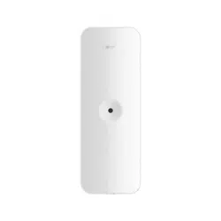
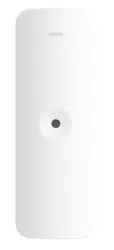
4.Rear Panel
English
1
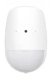
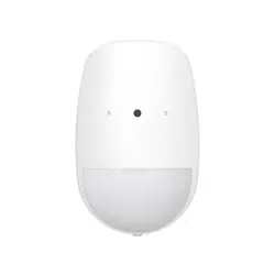
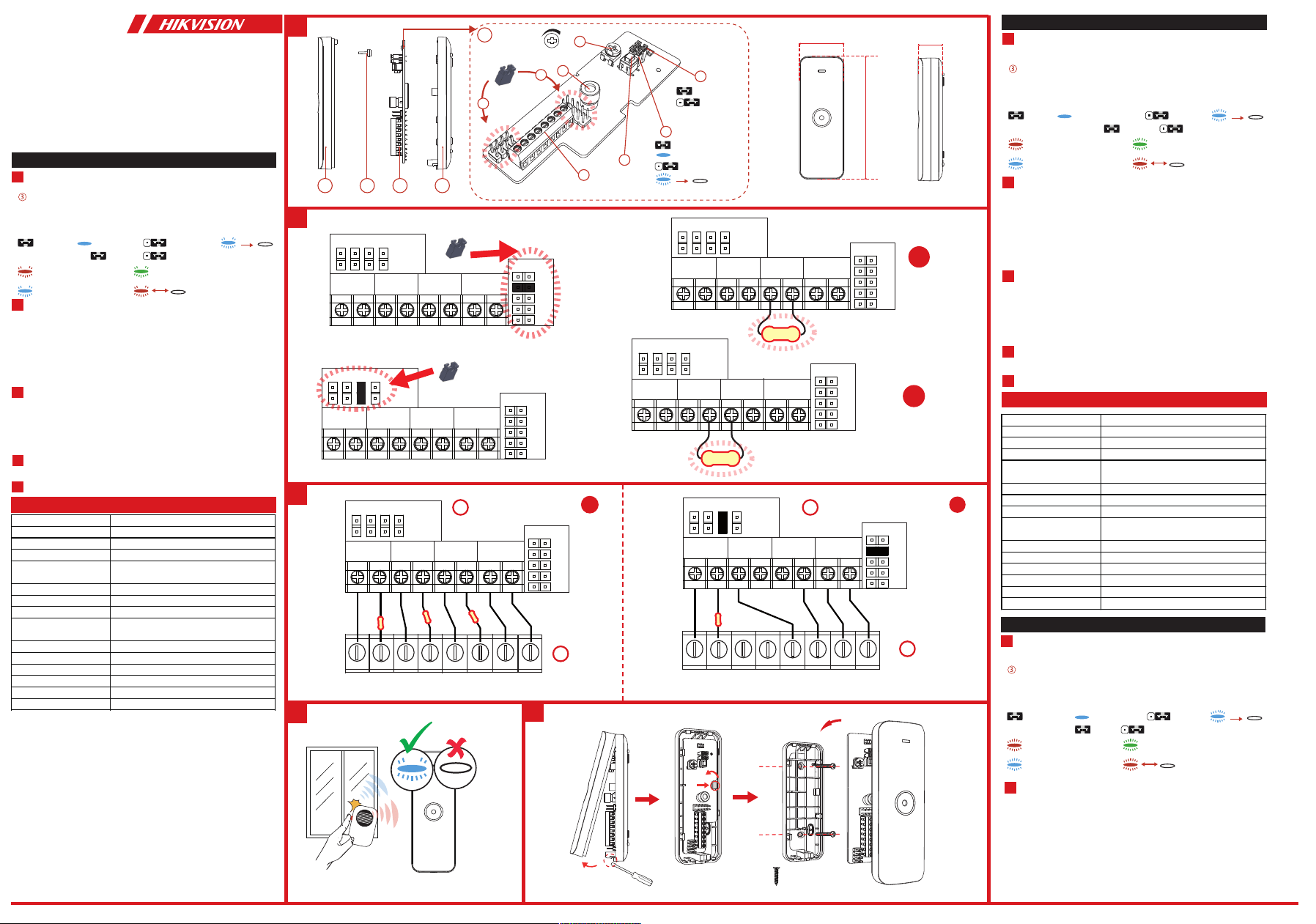
Appearance
2.LED Light Pipe1.Front Panel 3.PCB
The Printed Circuit Board (PCB)
4.Adjustable Resistance (Detection range: 0 to 8 m)
1.Tamper Resistor Headers
3.Sensor
2.Alarm Resistor Headers
Stay On
2s
High Frequency Trigger
Low Frequency Trigger
Alarm Fault
2s
Sensor Omnidirectional electret microphone
Power supply 8 to 16 VDC (standard: 12 VDC)
Current consumption 25mA quiescent and maximum at 12V DC
Detection range 8 m (25 ft)
Glass type
Float, plate, tempered, wired, laminated,
double glazing
Glass thickness 2.4 mm to 6.4 mm
Glass size 0.4 m × 0.4 m to 3 m × 3 m
Tamper protection Front
LED indicator
Blue (alarm), green (ex activation),
red (shatter activation)
Operating temperature -10°C to 55°C (14°F to 131°F)
Storage temperature -20°C to 60°C (-4°F to 140°F)
Operating humidity 10% to 90%
Installation Wall/Ceiling mount
Dimension (H×W×D) 107mm x 38.8mm x 22.5mm
Weight 49.5 g
BG (Break Glass) Test
Installation
5
Test
Specification
4
Resistor Wiring
2
Method 1: Use the jumper to select EOL (End of Line) resistance on
ALARM/TAMPER pins.
Method 2: Add the resistor to ALARM/TAMPER wiring ports.
Note: If EOL wiring is not used, leave the jumpers OFF. Do not force the
jumper if it is not matched the pin. Method 1 & 2 should not be used on the
ALARM/TAMPER at the same time.
a. Alarm Resistance: 1K, 2K2, 4K7, 5K6, 6K8
b. Tamper Resistance: 1K, 2K2, 4K7, 5K6
3 Connection Type
1.Detector
2.Alarm Control Panel
Note: The resistor must be connected in series with one end of the detector.
a. Normally Closed
b. Double End of Line Wiring:
The connection example: Normal: 1K, Alarm: 4.4K, Tamper: Innite
7.Alarm LED Latch/Normal
Latch Normal
8.LED ON/OFF
ON OFF
5.Terminal 6.Tamper
B
B
B
R
R
G
4.Rückwand
Deutsch
1
Aufbau
2.LED-Lichtrohr1.Frontplatte 3.Leiterplatte
Gedruckte Leiterplatte (PCB)
4.Einstellbarer Widerstand (Erkennungsbereich: 0 bis 8 m)
1.Stiftleisten des Sabotagewiderstands
3.Sensor
2.Stiftleisten des Alarmwiderstands
Anwesend Ein
2 s
Hochfrequenzauslöser
Niederfrequenzauslöser
Alarm Fehler
2 s
Widerstandsverdrahtung
2
Methode 1: Verwenden Sie die Steckbrücke, um Leitungsabschluss-
Widerstand (EOL) an ALARM/SABOTAGE-Kontaktstiften zu wählen.
Methode 2: Schließen Sie den Widerstand an den ALARM/
SABOTAGE-Verdrahtungsanschlüssen an.
Hinweis: Verwenden Sie KEINE Steckbrücken, wenn EOL-Verdrahtung nicht genutzt
wird. Die Steckbrücke darf nicht gewaltsam aufgesteckt werden, wenn sie nicht auf
den Kontaktstift passt. Methode 1 und 2 dürfen nicht gleichzeitig auf den
ALARM/SABOTAGE-Stiftleisten verwendet werden.
a. Alarmwiderstand: 1K, 2K2, 4K7, 5K6, 6K8
b. Sabotage-Widerstand: 1K, 2K2, 4K7, 5K6
7.Alarm-LED Verriegelung/Normal
Verriegelung Normal
8.LED AN/AUS
EIN AUS
5.Anschlussklemmen 6.Sabotage
1 1
Circuit imprimé (PCB)
4.Panneau arrière
Français
1
Apparence
2.Conducteur de lumière LED1.Panneau avant
3.PCB
4.Résistance réglable (plage de détection : 0 à 8 m)
1.Embases de résistance anti-sabotage
3.Capteur
2.Embases de résistance d'alarme
S’allume en continu
2 s
Déclencheur haute fréquence
Déclencheur basse fréquence
Alarme Panne
2 s
Capteur Microphone à électret omnidirectionnel
Alimentation électrique 8 à 16 V CC (standard : 12 V CC)
Consommation de courant 25 mA au repos et maximale à 12 V CC
Portée de détection 8 m
Type de verre Flotté, plat, trempé, armé, feuilleté et double vitrage
Épaisseur de verre 2,4 mm à 6,4 mm
Dimensions du verre 0,4 m × 0,4 m à 3 m × 3 m
Protection anti-sabotage Vue de face
Indicateur LED
Bleu (alarme), vert (activation si choc contre la vitre),
rouge (activation si vitre cassée)
Température de fonctionnement -10 à 55 °C
Température de stockage -20 °C à +60 °C
Humidité de fonctionnement 10 à 90 %
Installation Montage mural/au plafond
Dimensions (L x l x h) 107 mm x 38,8 mm x 24,5 mm
Poids 49,5 g
Test de BG (bris de glace)
Installation
5
Test
Spécification
4
Câblage des résistances2
Méthode 1 : utilisez le cavalier pour sélectionner la résistance d’extrémité de ligne
(EOL) sur les broches ALARME/ANTI-SABOTAGE.
Méthode 2 : ajoutez la résistance aux ports de câblage ALARME/ANTI-SABOTAGE.
Remarque : si vous n’utilisez pas de câblage EOL, les cavaliers doivent rester
désactivés. Ne forcez pas sur le cavalier s’il n’est pas adapté à la broche. Les méthodes
1 et 2 ne doivent pas être utilisées en même temps sur l’ALARME/ANTI-SABOTAGE.
a. Résistance d’alarme : 1K, 2K2, 4K7, 5K6, 6K8
b. Résistance anti-sabotage : 1K, 2K2, 4K7, 5K6
3 Type de connexion
1.Détecteur
2.Panneau de contrôle d’alarme
Remarque : la résistance doit être connectée en série à une des extrémités du détecteur.
a. normalement fermé
b. Câblage d’une double extrémité de ligne :
Exemple de connexion : Normal : 1K, alarme : 4,4K, anti-sabotage : innie
7.LED d’alarme : position verrouillée/normale
Verrou Normale
8.LED ALLUMÉE/ÉTEINTE
MARCHE ARRÊT
5.Borne 6.Anti-sabotage

Sensor Omnidirektionales Elektret-Mikrofon
Spannungsversorgung 8 bis 16 V DC (Standard: 12 V DC)
Stromaufnahme 25mA Ruhestrom und Maximum bei 12 V DC
Erkennungsbereich 8 m
Glasart
Spiegelglas, Flachglas, gehärtetes Glas,
Drahtglas, Bleiverbundglas, Doppelverglasung
Glasdicke 2,4 mm bis 6,4 mm
Glasgröße 0,4 m x 0,4 m bis 3 m x 3 m
Sabotageschutz Vorne
LED-Anzeige
Blau (Alarm), grün (exible Aktivierung),
rot (Aktivierung durch Glassplittern)
Betriebstemperatur -10 °C bis +55 °C
Lagertemperatur -20 °C bis +60 °C
Betriebsfeuchtigkeit 10 % bis 90 %
Installation Wand-/Deckenmontage
Maße (H x B x T) 107 mm x 38,8 mm x 24,5 mm
Gewicht 49,5 g
Glasbruchtest
5
Installation
Test
Technische Daten
4
Anschlussart3
1.Melder
2.Alarmzentrale
Hinweis: Der Widerstand muss mit einem Kontakt des Melders in Reihe geschaltet werden.
a. Normal geschlossen
b. Doppel-Leitungsabschlussverdrahtung:
Verdrahtungsbeispiel: Normal: 1K, Alarm: 4,4 K, Sabotage: Unbegrenzt
3.Placa de circuito impreso 4.Panel trasero
Español
1
Apariencia
2.Tubo de luz LED1.Panel frontal
Placa de circuito impreso
4.Resistencia ajustable (intervalo de detección: de 0 a 8 m)
1.Cabezales de la resistencia de seguridad
3.Sensor
2.Cabezales de resistencia de la alarma
Permanecer encendido
2 s
Disparador de alta frecuencia
Disparador de baja frecuencia
Alarma Fallo
2 s
Sensor Micrófono elect. omnidireccional
Fuente de alimentación De 8 a 16 VCC (estándar: 12 VCC)
Consumo de corriente 25mA en modo inactivo con un máximo de 12 V CC
Alcance de detección 8 m (25 pies)
Tipo de cristal
Flotado, placa de vidrio, templado, armado,
laminado y de doble acristalamiento
Grosor de cristal De 2,4 mm a 6,4 mm
Tamaño del vidrio De 0,4 m x 0,4 m a 3 m x 3 m
Protección antimanipulación Frontal
Piloto led
Azul (alarma), verde (activación exible) y rojo
(activación de rotura)
Temperatura de funcionamiento -10°C a 55°C (14°F a 131°F)
Temperatura de almacenamiento De -20 °C a 60 °C (-4 °F a 140 °F)
Humedad de funcionamiento 10 % a 90 %
Instalación Montaje en pared/techo
Dimensiones 107 mm × 38,8 mm × 24,5 mm
Peso 49,5 g
Prueba de rotura de vidrio
Instalación
5
Prueba
Especificación
4
Cableado de la resistencia2
Método 1: utilice el puente para seleccionar la resistencia de n de línea (EOL) en los pines
ALARMA/MANIPULACIÓN.
Método 2: añada la resistencia a los puertos de cableado ALARMA/
MANIPULACIÓN.
Nota: Si no usa un cableado de n de línea (EOL), deje los puentes desconectados. No
fuerce las resistencias si no coinciden con los pines.
No utilice el método 1 ni el método 2 con respecto a ALARMA/
MANIPULACIÓN al mismo tiempo.
a. Resistencia de alarma: 1K, 2K2, 4K7, 5K6, 6K8
b. Resistencia a manipulación: 1K, 2K2, 4K7, 5K6
3 Tipo de conexión
1.Detector
2.Panel de control de la alarma
Nota: La resistencia se debe conectar en serie con uno de los extremos del detector.
a. Normalmente cerrado
b. Cableado de doble n de línea:
Ejemplo de conexión: normal (1 K), alarma (4,4 K) y manipulación (innito)
7.Led de alarma circuito/normal
Circuito Normal
8.LED ACTIVADO/DESACTIVADO
ENCENDIDO APAGADO
5.Terminal 6.Sabotaje
Circuito stampato (PCB)
4.Pannello posteriore
Italiano
1
Aspetto
2.Illuminazione tubolare a LED1.Pannello anteriore
3.PCB
4.Resistenza regolabile (distanza di rilevamento: da 0 a 8 m)
1.Jumper resistenza antimanomissione
3.Sensore
2.Jumper resistenza allarme
Luce ssa
2 s
Attivazione ad alta frequenza
Attivazione a bassa frequenza
Allarme Errore
2 s
Sensore Microfono omnidirezionale a elettrete
Alimentazione da 8 a 16 VCC (standard: 12 VCC)
Assorbimento 25 mA quiescente; max 12 VCC
Area di copertura 8 m (25 piedi)
Tipo di vetro
Flottato, cristallo in lastre, temperato, retinato,
straticato, doppio vetro
Spessore del vetro da 2,4 a 6,4 mm
Dimensioni del vetro da 0,4 × 0,4 m a 3 × 3 m
Protezione antimanomissione Parte anteriore
Indicatore LED
Blu (allarme), verde (attivazione in seguito a essione),
rosso (attivazione in seguito a frantumazione)
Temperatura operativa Da -10 °C a 55 °C (da 14 °F a 131 °F)
Temperatura di conservazione Da -20 °C a 60 °C (da -4 °F a 140 °F)
Umidità operativa Da 10% a 90%
Installazione Montaggio a parete/a sotto
Dimensioni (A × L × P) 107 × 38,8 × 24,5 mm
Peso 49,5 g
Test di rottura del vetro (BG)
Installazione
5
Test
Specifiche
4
Cablaggio della resistenza2
Metodo 1: utilizzare il ponticello per selezionare la resistenza di ne linea (EOL) sui
perni ALLARME/MANOMISSIONE.
Metodo 2: aggiungere il resistore alle porte di cablaggio ALLARME/
MANOMISSIONE.
Nota: se non si utilizza il cablaggio EOL, lasciare i ponticelli DISINSERITI.
Non forzare i ponticelli se non si trovano in corrispondenza dei perni. Il primo e il
secondo metodo non devono essere utilizzati contemporaneamente.
a. Resistenza allarme: 1K, 2K2, 4K7, 5K6, 6K8
b. Resistenza antimanomissione: 1K, 2K2, 4K7, 5K6
3 Tipo di collegamento
1.Rilevatore
2.Pannello di controllo allarme
Nota: Il resistore deve essere collegato in serie con un terminale del rilevatore.
a. Normalmente chiuso
b. Cablaggio di ne linea doppio:
Esempio di collegamento: Normale: 1K, Allarme: 4,4 K, manomissione: Innita
7.LED di allarme latch/normale
Latch Normale
8.LED ACCESO/SPENTO
ATTIVO DISATTIVO
5.Morsettiera 6.Manomissione
4.Painel traseiro
Português
1
Apresentação
2.Tubo de luz de LED1.Painel frontal 3.PCB
Placa de circuito impresso (PCB)
4.Resistência ajustável (faixa de detecção: 0 a 8 m)
1.Cabeçotes do resistor antiviolação
3.Sensor
2.Cabeçotes do resistor de alarme
Permanecer ligado
2 s
Acionamento de alta
frequência
Acionamento de baixa frequência
Alarme Falha
2 s
Sensor Microfone de eletreto omnidirecional
Fonte de alimentação 8 a 16 VCC (padrão: 12 VCC)
Consumo de corrente 25mA em inatividade e máxima em 12 VCC
Alcance de detecção 8 m (25 pés)
Tipo de vidro
Float, plano, temperado, aramado,
laminado, insulado
Espessura do vidro 2,4 mm a 6,4 mm
Tamanho do vidro 0,4 m × 0,4 m a 3 m × 3 m
Proteção antiviolação Parte dianteira
Indicador LED
Azul (alarme), verde (ativação exível),
vermelho (ativação de quebra)
Temperatura de operação -10 °C a 55 °C (14 °F a 131 °F)
Temperatura de armazenamento -20 °C a 60 °C (-4 °F a 140 °F)
Umidade de operação 10% a 90%
Instalação Montagem na parede/teto
Dimensões (A × L × P) 107 mm × 38,8 mm × 24,5 mm
Peso 49,5 g
Teste BG (Quebra de vidro)
Instalação
5
Teste
Especificações
4
Conexão do resistor2
Método 1: use o jumper para selecionar a resistência EOL (m de linha) nos
pinos ALARME/VIOLAÇÃO.
Método 2: adicione o resistor às portas de ação ALARME/VIOLAÇÃO.
Observação: se a ação EOL não for usada, deixe os jumpers desligados.
Não force o jumper se ele não corresponder ao pino. Os métodos 1 e 2 não
devem ser usados em ALARME/VIOLAÇÃO ao mesmo tempo.
a. Resistência do alarme: 1K, 2K2, 4K7, 5K6, 6K8
b. Resistência de antiviolação: 1K, 2K2, 4K7, 5K6
Tipo de conexão3
1.Detector
2.Painel de controle de alarme
Observação: o resistor deve ser conectado em série com uma extremidade do detector.
a. Normalmente fechado
b. Fiação de m de linha duplo:
Exemplo de conexão: Normal: 1K; alarme: 4,4K; violação: Innito
7.Trava do LED de alarme/Normal
Trava Normal
8.LED LIG/DESLIG
LIGADO DESLIGADO
5.Terminal 6.Violação
4.Achterpaneel
Nederlands
1
Uiterlijk
2.Pijp met led-licht
1.Voorpaneel 3.PCB
De printplaat (PCB)
4.Aanpasbare weerstand (Detectiebereik: 0 tot 8m)
1.Sabotagebestendige koppen
3.Sensor
2.Alarmbestendige koppen
Blijf aan
2s
Hoge frequentietrigger
Lage frequentietrigger
Alarm Storing
2s
Sensor Omnidirectionele elektreetmicrofoon
Stroomvoorziening 8 tot 16 VDC (standaard: 12 VDC)
Stroomverbruik 25mA in rust en maximaal bij 12V gelijkstroom
Detectiebereik 8 m
Glastype
Zwevend, plaat, gehard, bedraad,
gelamineerd, dubbele beglazing
Glasdikte 2,4 mm tot 6,4 mm
Glasformaat 0,4 m × 0,4 m tot 3 m × 3 m
Sabotagebescherming Voorzijde
Led-indicator
Blauw (alarm), groen (ex activatie),
rood (versplinteractivering)
Bedrijfstemperatuur -10°C tot 55°C
Opslagtemperatuur -20°C tot 60°C
Bedrijfsvochtigheid 10% tot 90%
Installatie Wand-/plafondmontage
Afmetingen (H×B×D) 107 mm × 38.8 mm × 24.5 mm
Gewicht 49,5 g
BG (glasbreuk)-test
5
Installatie
Testen
Specificatie
4
Bedrading van weerstand2
Methode 1: Gebruik de jumper om EOL (Einde van de regel) -weerstand te
selecteren op ALARM/SABOTAGE-pins.
Methode 2: Voeg de weerstand toe op ALARM/
SABOTAGE-bedradingspoorten.
Opmerking: Als EOL-bedrading niet wordt gebruikt, laat u de jumpers uit.
Forceer de jumper niet als deze niet overeenkomt met de pin. Methode 1 & 2
mogen niet worden gebruikt op het ALARM/SABOTAGE tegelijkertijd.
a. Alarmweerstand: 1K, 2K2, 4K7, 5K6, 6K8
b. Sabotageweerstand: 1K, 2K2, 4K7, 5K6
3 Verbindingstype
1.Detector
2.Bedieningspaneel alarm
Opmerking: De weerstand moet verbonden zijn in series met een eind van
de detector.
a. Normaal gesloten
b. Dubbel einde van de lijnbedrading:
Voorbeeld van de verbinding: Normaal: 1K, Alarm: 4.4K, Sabotage: Oneindig
7.Alarm-led Grendel/normaal
Grendel Normaal
8.LED AAN/UIT
AAN UIT
5.Aansluitklem 6.Saboteren
4.Zadní panel
Čeština
1
Vzhled
2.Světlovod LED1.Přední panel 3.PCB
Deska s plošnými spoji (PCB)
4.Nastavitelný odpor (rozsah detekce: 0 až 8 m)
1.Sběrače rezistoru neoprávněné manipulace
3.Snímač
2.Sběrače rezistoru alarmu
Ponechat zapnuté
2 s
Spouštěč vysoké frekvence
Spouštěč nízké frekvence
Alarm Porucha
2 s
Snímač Všesměrový elektretový mikrofon
Napájení 8 až 16 V stejnosm. (standardně: 12 V stejnosm.)
Spotřeba energie Klidový a maximální proud 25 mA při 12 V DC
Rozsah detekce 8 m
Typ skla
Plavené, tabulové, temperované, drátěné, vrstvené,
s dvojitým zasklením
Tloušťka skla 2,4 mm až 6,4 mm
Rozměry skla 0,4 m × 0,4 m až 3 m × 3 m
Ochrana proti neoprávněné
manipulaci
Přední
Indikátor LED
Modrá (alarm), zelená (aktivace prohnutím),
červená (aktivace rozbitím)
Provozní teplota −10 °C až 55 °C
Skladovací teplota -20 °C až 60 °C
Provozní vlhkost 10 % až 90 %
Montáž Na zeď / na strop
Rozměry (V׊×H) 107 mm × 38,8 mm × 24,5 mm
Hmotnost 49,5 g
Test BG (tříštění skla, „Break Glass“)
Montáž
5
Test
Technické údaje
4
Zapojení rezistoru2
Metoda 1: K výběru odporu EOL (na konci linky) použijte propojku na pinech ALARM /
NEOPRÁVNĚNÁ MANIPULACE.
Metoda 2: Doplňte odpor na otvory pro kabeláž ALARM / NEOPRÁVNĚNÁ MANIPULACE.
Poznámka: Pokud není použito zapojení EOL, ponechejte propojky VYPNUTÉ. Pokud
propojka nesedí na kolíky, netlačte na ni silou. Metoda 1 a metoda 2 nesmí být na
detektoru ALARM / NEOPRÁVNĚNÁ MANIPULACE použity současně.
a. Odpor alarmu: 1K, 2K2, 4K7, 5K6, 6K8
b. Odpor neoprávněné manipulace: 1K, 2K2, 4K7, 5K6
3 Typ připojení
1.Detektor
2.Ovládací panel alarmu
Poznámka: Odpor musí být zapojen do série s jedním koncem detektoru.
a. Normálně uzavřeno
b. Dvojité zapojení konce linky:
Příklad zapojení: Normální: 1K, alarm: 4.4K, Neoprávněná manipulace: Nekonečno
7.LED alarmu západky / normální
Západka Normální
8.Zap./vyp. LED
ZAPNUTO VYPNUTO
5.Svorkovnice 6.Detektor sabotáže
4.Bagpanel
Dansk
1
Udseende
2.LED-lysrør1.Frontpanel 3.Printkort
Printkortet (PCB)
4.Justerbar modstand (Detektionsområde: 0 til 8 m)
1.Koblingspunkter for manipulationsmodstand
3.Sensor
2.Koblingspunkter for alarmmodstand
Forbliv tændt
2s
Højfrekvensudløsning
Lavfrekvensudløsning
Alarm Fejl
2s
Kabelføring af modstand
2
Metode 1: Brug jumperen til at vælge EOL (End of Line)-modstand på benene
for ALARM/MANIPULATION.
Metode 2: Føj modstanden til kablingsportene for ALARM/MANIPULATION.
Bemærk: Hvis EOL-kabelføring ikke anvendes, skal jumperne IKKE sættes på.
Tving ikke jumperen, hvis den ikke passer med benet. Metode 1 og 2 bør ikke
anvendes på ALARM/MANIPULATION samtidig.
a. Alarmmodstand: 1K, 2K2, 4K7, 5K6, 6K8
b. Manipulationsmodstand: 1K, 2K2, 4K7, 5K6
7.Alarm-LED Lås/Normal
Lås Normal
8.LED FOR TÆNDT/SLUKKET
TÆNDT SLUKKET
5.Terminal
6.Manipulation

Sensor Retningsuafhængig mikrofon
Strømforsyning 8 til 16 V jævnstrøm (standard: 12 V jævnstrøm)
Strømforsyning 25mA hvilestrøm og maks. ved 12V jævnstrøm
Detektionsrækkevidde 8 m
Glastype
Floatglas, pladeglas, hærdet glas, trådglas,
lamineret glas, dobbeltglas
Glastykkelse 2,4 mm til 6,4 mm
Glasstørrelse 0,4 m × 0,4 m til 3 m × 3 m
Manipulationsbeskyttelse Front
LED-kontrollampe
Blå (alarm), grøn (aktivering ved påvirkning),
rød (aktivering ved brud)
Driftstemperatur -10 °C til 55 °C
Opbevaringstemperatur -20 °C til 60 °C
Luftfugtighed ved drift 10-90 %
Installation Montering på væg/loft
Mål (H × B × D) 107 mm × 38,8 mm × 24,5 mm
Vægt 49,5 g
BG-test (glasbrud)
Installation
5
Test
Specifikation
4
Forbindelsestype3
1.Detektor
2.Alarmkontrolpanel
Bemærk: Modstanden skal serieforbindes med detektorens ene ende.
a. Normalt lukket
b. Dobbelt EOL-kabelføring:
Tilslutningseksemplet: Normal: 1K, alarm: 4,4K, Manipulation: Uendelig
4.Hátsó panel
Magyar
1
Külső megjelenés
2.LED-es fénycső1.Elülső panel 3.NYÁK
A nyomtatott áramkör (NYÁK)
4.Beállítható ellenállás (észlelési tartomány: 0 – 8 m)
1.Szabotázsellenállás jumperei
3.Érzékelő
2.Riasztóellenállás jumperei
Bekapcsolva marad
2s
Nagyfrekvenciás kioldó
Kisfrekvenciás kioldó
Riasztó Hiba
2s
Üvegtörés (BG) teszt
Telepítés
5
Teszt
Specifikáció
4
Ellenállás bekötése2
1. módszer: A jumperrel válassza ki az EOL (vonal vége) ellenállást az RIASZTÁS/SZ-
ABOTÁZS tűkön.
2. módszer: Adja hozzá az ellenállást az RIASZTÁS/SZABOTÁZS bekötési portokhoz.
Megjegyzés: Ha nem az EOL bekötést használja, akkor a jumpereket hagyja KI állásban.
Ne erőltesse a jumpert, ha az nem illik a tűhöz. Az RIASZTÁS/
SZABOTÁZS érintkezőn az 1. és a 2. módszer nem használható egyszerre.
a. Riasztás-ellenállás: 1k, 2k2, 4k7, 5k6, 6k8
b. Szabotázs-ellenállás: 1k, 2k2, 4k7, 5k6
3 Csatlakozás típusa
1.Detektor
2.Riasztó vezérlőpanelje
Megjegyzés: Az ellenállást sorosan kell csatlakoztatni az érzékelő egyik végéhez.
a. Nyitóérintkező
b. Vonalhuzalozás dupla vége:
A csatlakozási példa: Normál: 1k, Riasztás: 4,4k, Szabotázs: Végtelen
7.Riasztási LED retesz/normál
Retesz Normál
8.LED BE/KI
BE KI
5.Csatlakozó 6.Szabotázs
4.Panel tylny
Polski
1
Element
2.Światłowód wskaźnika1.Panel przedni
3.Płyta z obwodami drukowanymi (PCB)
Płyta z obwodami drukowanymi (PCB)
4.Regulowana rezystancja (zasięg detekcji: 0–8 m)
1.Złącza rezystorów zabezpieczenia antysabotażowego
3.Czujnik
2.Złącza rezystorów obwodu alarmowego
Włączony
2 s
Wyzwolenie
(duża częstotliwość)
Wyzwolenie (mała częstotliwość)
Alarm
Usterka
2 s
Érzékelő Mindenirányú elektret mikrofon
Tápfeszültség 8 – 16 V DC (standard: 12 V DC)
Áramfelvétel
25mA nyugalmi áram és maximum 12VDC feszültség
Észlelési tartomány 8 m
Üveg típusa
Úszó-, sík-, edzett üveg, vezetékes üveg,
laminált üveg, kettős üvegezésű üveg
Üveg vastagsága 2,4 mm – 6,4 mm
Üveg mérete 0,4 m × 0,4 m – 3 m × 3 m
Szabotázsvédelem Elülső
LED
Kék (riasztás), zöld (huzalos aktiválás),
piros (betöréses aktiválás)
Üzemi hőmérséklet -10 °C – 55 °C
Tárolási hőmérséklet -20°C – 60°C
Üzemi páratartalom 10% – 90%
Telepítés Falra/mennyezetre szerelhető
Méretek (ma × szé × mé) 107 mm × 38,8 mm × 24,5 mm
Súly 49,5 gramm
Czujnik Dookólny mikrofon elektretowy
Zasilanie 8– V DC (standard: 12 V DC)
Pobór prądu
25mA w trybie gotowości; wartość maksymalna przy 12VDC
Zasięg detekcji 8 m
Typ szyby
Float, płaska, powlekana, hartowana, zbrojona,
laminowana, podwójna
Grubość szyby 2,4 – 6,4 mm
Wymiary szyby 0,4 m × 0,4 m – 3 m × 3 m
Zabezpieczenie antysabotażowe Przód
Wskaźnik
Niebieski (alarm), zielony (aktywacja przez naprężenie),
czerwony (aktywacja przez pęknięcie)
Temperatura (użytkowanie) Od –10°C do 55°C
Temperatura (przechowywanie) Od –20°C do 60°C
Wilgotność (użytkowanie) Od 10% do 90%
Instalacja Montaż ścienny/sutowy
Wymiary (wys. × szer. × głęb.) 107 mm × 38,8 mm × 24,5 mm
Waga 49,5 g
Test detekcji pęknięcia szyby
Instalacja
5
Test
Specyfikacje
4
Podłączenie rezystora2
Metoda 1: Ustaw kongurację rezystancji EOL przy użyciu zworki na końcówkach
ALARM/SABOTAŻ.
Metoda 2: Podłącz rezystor do zacisków ALARM/SABOTAŻ.
Uwaga: Jeżeli konguracja połączeń EOL nie jest używana, należy usunąć zworki. Nie
wolno dociskać zworki, jeżeli nie pasuje ona do końcówek.
Nie wolno używać metod 1 i 2 równocześnie do wykonania połączeń ALARM/SABOTAŻ.
a. Rezystancja alarmu: 1k, 2k2, 4k7, 5k6, 6k8
b. Rezystancja sabotażu: 1k, 2k2, 4k7, 5k6
3 Typ połączenia
1.Detektor
2.Centrala alarmowa
Uwaga: Rezystor musi być podłączony szeregowo do jednego ze złączy detektora.
a. Rozwierne
b. Połączenia DEOL:
Przykład połączeń: Stan normalny: 1 k, alarm: 4,4 k, sabotaż: otwarcie obwodu
7.Wskaźnik alarmu (blokowany/normalny)
Blokada Zwykła
8.WSKAŹNIK WŁ./WYŁ.
WŁ. WYŁ.
5.Złącza
6.Sabotaż
4.Panou spate
Română
1
Aspect
2.Fir lumină LED1.Panou frontal 3.PCB
Placa de circuit imprimat (PCB)
4.Rezistenţă reglabilă (interval de detecţie: 0 până la 8m)
1.Antete rezistenţă alterare
3.Senzor
2.Antete rezistenţă alarmă
Rămâi pe poziţie
2 s
Declanşator de înaltă
frecvenţă
Declanşator de frecvenţă joasă
Alarmă Eroare
2 s
Testul BG (spargere sticlă)
5
Instalarea
Test
Senzor Microfon electret omnidirecţional
Alimentare electrică De la 8 până la 16 Vc.c (standard: 12 Vc.c. )
Consum curent 25mA în repaus şi maxim la 12V c.c.
Interval detectare 8 m
Tip de sticlă
Flotor, placă, temperat, cu r, laminat,
glazurare dublă
Grosimea sticlei De la 2,4 mm până la 6,4 mm
Dimensiunea sticlei De la 0,4 m × 0,4 m până la 3 m × 3 m
Protecţie alterare Frontal
Indicator LED
Albastru (alarmă), verde (activare ex),
roşu (activare impact)
Temperatura de funcţionare De la -10°C la 55°C (de la 14°F la 131°F)
Temperatura de păstrate De la -20°C până la 60°C (de la -4°F până la 140°F)
Umiditatea de operare De la 10% la 90%
Instalarea Montare pe perete/tavan
Dimensiune (Î×L×D) 107 mm × 38,8 mm × 24,5 mm
Greutate 49,5 g
Specificaţii
4
Cablarea reziatenţei2
Metoda 1: Utilizaţi xatorul pentru a selecta rezistenţa EOL (End of Line) pe pinii
ALARMĂ/ALTERARE.
Metoda 2: Adăugaţi rezistorul la porturile de cabluri ALARMĂ/ALTERARE.
Notă: Dacă cablajul EOL nu este utilizat, lăsaţi xatorii OPRIŢI. Nu forţaţi xatorul
dacă nu se potriveşte cu ştiftul. Metoda 1 şi 2 nu trebuie utilizată simultan pe
ALARMĂ/ALTERARE.
a. Rezistenţă alarmă: 1K, 2K2, 4K7, 5K6, 6K8
b. Rezistenţă alterare: 1K, 2K2, 4K7, 5K6
3 Tipul conexiunii
1.Detector
2.Panou de control alarmă
Notă: Rezistorul trebuie conectat în serie cu un capăt al detectorului.
a. În mod normal închis
b. Capătul dublu al liniei de cablaj:
Exemplu de conexiune: Normal: 1K, Alarmă: 4.4K, Tamper: Innită
7.Alarmă LED Lacăt/Normal
Lacăt Normal
8.LED PORNIT/OPRIT
PORNIT OPRIT
5.Terminal 6.Modicare
4.Zadný panel
Slovenčina
1
Vzhľad
2.Svetelná trubica LED
1.Predný panel 3.Plošne spoje
Doska plošných spojov (PCB)
4.Nastaviteľný odpor (rozsah detekcie: 0 až 8 m)
1.Hlavičky odporníkov manipulácie
3.Snímač
2.Hlavičky odporníkov alarmu
Trvale svieti
2 s
Vysokofrekvenčný spúšťač
Nízkofrekvenčný spúšťač
Alarm Chyba
2 s
Snímač Všesmerový elektrétový mikrofón
Napájanie 8 až 16 V DC (štandardné: 12 V DC)
Spotreba prúdu
25mA v pokojovom režime a maximálne pri 12VDC
Rozsah detekcie 8 m (25 stôp)
Druh skla
Plavené, tabuľové, tvrdené, drôtené,
laminované, dvojité zasklenie
Hrúbka skla 2,4 mm až 6,4 mm
Veľkosť skla 0,4 m × 0,4 m až 3 m × 3 m
Ochrana proti manipulácii Predný
LED indikátor
Modrý (alarm), zelený (aktivácia pri ohnutí),
červený (aktivácia pri rozbití)
Prevádzková teplota -10 °C až 55 °C (14 °F až 131 °F)
Teplota skladovania -20 °C až 60 °C (-4 °F až 140 °F)
Prevádzková vlhkosť 10 % až 90 %
Montáž Montáž na stene/strope
Rozmery (V × Š × H) 107 mm × 38,8 mm × 24,5 mm
Hmotnosť 49,5 g
Test BG (rozbitie skla)
Montáž
5
Test
Špecifikácie
4
Zapojenie odporníka2
Spôsob 1: Pomocou mostíka vyberte odpor EOL (koniec vedenia) na kolíkoch
ALARM/MANIPULÁCIA.
Spôsob 2: Pridajte odporník do portov zapojenia ALARM/MANIPULÁCIA.
Poznámka: Ak sa zapojenie EOL nepoužíva, nechajte mostík ako VYPNUTÉ.
Ak mostík nezapadne na kolíky, netlačte ho silou. Spôsoby 1 a 2 sa nesmú na
kolíkoch ALARM/MANIPULÁCIA použiť súčasne.
a. Odpor alarmu: 1K, 2K2, 4K7, 5K6, 6K8
b. Odpor pri manipulácii: 1K, 2K2, 4K7, 5K6
3 Typ pripojenia
1.Detektor
2.Ovládací panel alarmu
Poznámka: Odporník musí byť pripojený do série k jednmu koncu detektora.
a. Normálne prepojenie
b. Zapojenie dvojitého konca vedenia:
Príklad pripojenia: Normálny: 1 K, Alarm: 4,4 K, Manipulácia: Nekonečný
7.Prepínač LED alarmu/normálne
Prepínač
Normálna
8.LED ZAP/VYP
ZAPNUTÉ VYPNUTÉ
5.Svorkovnica 6.Manipulácia
4.Arka Panel
Türkçe
1
Görünüm
2.LED Işıklı Boru1.Ön Panel 3.PCB
Basılı Devre Kartı (PCB)
4.Ayarlanabilir Direnç (Algılama aralığı: 0 ila 7.6m)
1.Kurcalama Rezistans Başlıkları
3.Sensör
2.Alarm Rezistans Başlıkları
Açık Kal
2sn
Yüksek Frekans Tetikleyici
Düiük Frekans Tetikleyici
Alarm Arıza
2sn
Sensör Çok yönlü elektret mikrofon
Güç kaynağı 8 ila 16 VDC (standart: 12 VDC)
Akım tüketimi 25mA sessiz ve 12 V DC'de maksimum
Algılama aralığı 8 m (25 ft)
Cam türü Yüzer, levha, temperli, telli, lamine, çift cam
Cam kalınlığı 2,4 mm ila 6,4 mm
Cam boyutu 0,4 m × 0,4 m ila 3 m × 3 m
Kurcalama koruması Ön Taraf
LED göstergesi
Mavi (alarm), yeşil (esnek aktivasyon),
kırmızı (parçalama aktivasyonu)
Çalışma sıcaklığı -10°C ila 55°C (14°F ila 131°F)
Depolama sıcaklığı -20°C ila 60°C (-4°F ila 140°F)
Çalışma nemi %10 ila %90
Kurulum Duvara/Tavana montaj
Boyut (Y×G×D) 107 mm × 38.8 mm × 24.5 mm
Ağırlık 49,5 g
BG (Cam Kırılma) Testi
5
Kurulum
Test
Özellikler
4
Rezistans Kabloları2
Yöntem 1: ALARM/KURCALAMA pinlerinde EOL (Hat Sonu) direncini seçmek
için atlama telini kullanın.
Yöntem 2: Direnci ALARM/KURCALAMA kablo bağlantı noktalarına ekleyin.
Not: EOL kabloları kullanılmıyorsa, atlama tellerini KAPALI bırakın. Pime
uymuyorsa atlama telini zorlamayın. ALARM/KURCALAMA üzerinde
yöntem 1 ve 2 aynı anda kullanılmamalıdır.
a. Alarm Direnci: 1K, 2K2, 4K7, 5K6, 6K8
b. Kurcalama Direnci: 1K, 2K2, 4K7, 5K6
3 Bağlantı Tipi
1.Dedektör
2.Alarm Kontrol Paneli
Not: Direnç, dedektörün bir ucu ile seri bağlanmalıdır.
a. Normalde Kapalı
b. Çift Hat Sonu Kablolaması:
Bağlantı örneği: Normal: 1K, Alarm: 4.4K, Kurcalama: Sonsuz
7.Alarm LED Mandal/Normal
Mandal Normal
8.LED AÇIK/KAPALI
Açık KAPALI
5.Terminal 6.Kurcalama

Legal and Regulatory Information
Français
©2020 Hangzhou Hikvision Digital Technology Co., Ltd. Tous droits réservés.
À propos de ce manuel
Ce manuel fournit des instructions d’utilisation et de gestion du produit. Les images, les tableaux, les gures et toutes les autres informations ci-après ne sont donnés qu’à titre de description et
d’explication. Les informationscontenues dans ce manuel sont modiables sans préavis, en raison d’une mise à jour d’un micrologiciel ou pourd’autres raisons. Veuillez trouver la dernière
version de ce manuel sur le site Internet de Hikvision (https://www.hikvision.com/).
Veuillez utiliser ce mode d’emploi avec les conseilset l’assistance de professionnels spécialement formés dans laprise en charge de ce produit.
et les autres marques et logos de Hikvision sont la propriété de Hikvision dans diverses juridictions. Toutes les autres marques et tousles logos mentionnés appartiennent à
leurs propriétaires respectifs.
Clause d’exclusion de responsabilité
DANSLES LIMITESAUTORISÉES PARLA LOI EN VIGUEUR, LE PRÉSENT MANUEL ET LE PRODUITDÉCRIT, AINSI QUE SON MATÉRIEL, SES LOGICIELS ET SES MICROLOGICIELS, SONT FOURNIS« EN L’ÉTAT » ET
« AVEC TOUS LES DÉFAUTSET ERREURS ». HIKVISION NE FAIT AUCUNEGARANTIE, EXPLICITE OU IMPLICITE,Y COMPRIS, MAIS SANS S’Y LIMITER, DE QUALITÉ MARCHANDE, DE QUALITÉ SATISFAISANTE,
OU D’ADÉQUATION À UN USAGE PARTICULIER.VOUS UTILISEZ LE PRODUIT À VOS PROPRESRISQUES.EN AUCUN CAS HIKVISION NE SERA TENU RESPONSABLE POUR TOUT DOMMAGESPÉCIAL,
CONSÉCUTIF, ACCESSOIRE OU INDIRECT, Y COMPRIS,ENTRE AUTRES, LES DOMMAGES RELATIFS À LA PERTE DE PROFITS D’ENTREPRISE, À L’INTERRUPTIOND’ACTIVITÉS COMMERCIALES,OU LA PERTE DES
DONNÉES, LA CORRUPTION DES SYSTÈMES, OU LA PERTEDES DOCUMENTS, S’ILS SONT BASÉS SUR UNE VIOLATION DE CONTRAT,UNE FAUTE(Y COMPRIS LA NÉGLIGENCE), LA RESPONSABILITÉ EN
MATIÈRE DE PRODUITS, OU AUTRE, EN RAPPORT AVECL’UTILISATION DU PRODUIT, MÊME SI HIKVISIONA ÉTÉ INFORMÉ DE LA POSSIBILITÉ D’UN TEL DOMMAGEOU D’UNE TELLEPERTE.
VOUSRECONNAISSEZ QUE LA NATURE D’INTERNETEST SOURCEDE RISQUES DE SÉCURITÉ INHÉRENTS,ET HIKVISION SE DÉGAGE DE TOUTE RESPONSABILITÉEN CAS DE FONCTIONNEMENTANORMAL,
DIVULGATION D’INFORMATIONS CONFIDENTIELLESOU AUTRES DOMMAGESDÉCOULANT D’UNE CYBERATTAQUE, D’UN PIRATAGE INFORMATIQUE, D’UNE INFECTIONPARDES VIRUS, OU AUTRES
RISQUES DE SÉCURITÉ LIÉS À INTERNET ; TOUTEFOIS, HIKVISIONFOURNIRA UNE ASSISTANCE TECHNIQUE DANSLES DÉLAIS, LE CAS ÉCHÉANT.
VOUSACCEPTEZ D’UTILISER CE PRODUIT CONFORMÉMENT À L’ENSEMBLEDES LOIS EN VIGUEUR. IL EST DE VOTRERESPONSABILITÉEXCLUSIVE DE VEILLER À CE QUE VOTRE UTILISATIONSOIT
CONFORME À LA LOI APPLICABLE. IL VOUS APPARTIENT SURTOUT D’UTILISER CE PRODUITD’UNE MANIÈREQUI NE PORTE PAS ATTEINTE AUX DROITS DE TIERS, Y COMPRIS, MAIS SANS S’Y LIMITER, LES
DROITS DE PUBLICITÉ,LES DROITS DE PROPRIÉTÉINTELLECTUELLE,OU LA PROTECTION DES DONNÉESET D’AUTRES DROITS À LA VIEPRIVÉE.VOUS NE DEVEZ PASUTILISER CE PRODUIT POUR TOUTE
UTILISATION FINALEINTERDITE, NOTAMMENT LA MISE AU POINTOU LA PRODUCTIOND’ARMES DE DESTRUCTION MASSIVE, LA MISEAU POINT OU LA FABRICATIOND’ARMES CHIMIQUES OU
BIOLOGIQUES, LES ACTIVITÉS DANSLE CONTEXTE LIÉ AUX EXPLOSIFS NUCLÉAIRES OU AU CYCLE DU COMBUSTIBLE NUCLÉAIRE DANGEREUX, OU SOUTENANT LES VIOLATIONS DES DROITSDE L’HOMME.
EN CAS DE CONFLIT ENTRE CE MANUELET LES LOIS EN VIGUEUR, CES DERNIÈRESPRÉVALENT.
Ce produit et, le cas échéant, les accessoires qui l’accompagnent, sont estampillés « CE » et sont doncconformes aux normes européennes harmonisées en vigueur répertoriées sous
la directive relative auxéquipements radioélectriques 2014/53/UE, la directive sur les émissionsélectromagnétiques 2014/30/UE et la directive RoHS 2011/65/UE.
2012/19/UE (directive DEEE) : Dans l’Union européenne, les produits portant ce pictogramme ne doivent pas être déposés dans une décharge municipale où le tri des déchets n’est
pas pratiqué. Pour un recyclage adéquat, remettez ce produit à votre revendeur lors de l’achat d’un nouvel équipement équivalent, ou déposez-le dans un lieu de collecte prévu à cet
eet. Pour de plus amples informations, consultez : www.recyclethis.info.
2006/66/CE (directive sur les batteries) : Ce produit renferme une batterie qui ne doit pas être déposée dans une décharge municipale où le tri des déchets n’est pas pratiqué, dans
l’Union européenne. Pour plus de précisionssur la batterie, reportez-vous à sa documentation.La batterie porte le pictogramme ci-contre, qui peut inclure la mention Cd (cadmium),
Pb (plomb) ou Hg (mercure). Pour larecycler correctement, renvoyez la batterie à votre revendeur ou déposez-la dans un point de collecte prévu à cet eet. Pour de plus amples
informations, consultez : www.recyclethis.info.
PRÉCAUTION D’INSTALLATION
La force supplémentaire doit être égale à trois fois le poidsde l’équipement et au minimum à 50 N. L’équipement et ses supports de montage doivent être maintenus fermement
en place pendant l’installation. Après l’installation, l’équipement, y compris le plateau de montage associé le cas échéant, ne doit pas être endommagé.
English
©2020 Hangzhou Hikvision Digital Technology Co., Ltd. All rights reserved.
About this Manual
The Manual includes instructions for using and managing the Product. Pictures, charts, images and all other information hereinafter are for description and explanation only. The information
contained in the Manual is subject to change, without notice, due to rmware updates or other reasons. Please nd the latest version of this Manual at the Hikvision website
(https://www.hikvision.com/).
Please use this Manual with the guidance and assistance of professionals trained in supporting the Product.
and other Hikvision's trademarks and logos are the properties of Hikvision in various jurisdictions. Other trademarks and logos mentioned are the properties of their respective
owners.
Disclaimer
TO THE MAXIMUM EXTENT PERMITTED BY APPLICABLE LAW, THIS MANUAL AND THE PRODUCT DESCRIBED, WITH ITS HARDWARE, SOFTWARE AND FIRMWARE, ARE PROVIDED “AS IS” AND “WITH ALL
FAULTS AND ERRORS”. HIKVISION MAKESNO WARRANTIES, EXPRESS OR IMPLIED, INCLUDING WITHOUT LIMITATION, MERCHANTABILITY, SATISFACTORY QUALITY, OR FITNESS FOR A PARTICULAR
PURPOSE. THE USE OF THE PRODUCT BY YOU IS AT YOUR OWN RISK. IN NO EVENTWILL HIKVISION BE LIABLETO YOU FOR ANY SPECIAL, CONSEQUENTIAL,INCIDENTAL,OR INDIRECT DAMAGES,
INCLUDING, AMONG OTHERS, DAMAGES FOR LOSS OF BUSINESS PROFITS, BUSINESS INTERRUPTION, OR LOSS OF DATA, CORRUPTION OF SYSTEMS, OR LOSS OF DOCUMENTATION, WHETHER BASED ON
BREACH OF CONTRACT,TORT(INCLUDING NEGLIGENCE), PRODUCTLIABILITY, OR OTHERWISE, IN CONNECTION WITH THE USE OF THE PRODUCT, EVENIF HIKVISION HAS BEEN ADVISED OF THE
POSSIBILITY OF SUCH DAMAGES OR LOSS.
YOU ACKNOWLEDGE THAT THE NATURE OF THE INTERNET PROVIDES FOR INHERENT SECURITY RISKS, AND HIKVISION SHALLNOT TAKEANY RESPONSIBILITIES FOR ABNORMAL OPERATION,PRIVACY
LEAKAGE OR OTHER DAMAGES RESULTING FROM CYBER-ATTACK, HACKER ATTACK, VIRUS INFECTION,OR OTHER INTERNET SECURITYRISKS;HOWEVER, HIKVISION WILL PROVIDE TIMELY TECHNICAL
SUPPORT IF REQUIRED.
YOU AGREE TO USE THIS PRODUCT IN COMPLIANCE WITH ALL APPLICABLE LAWS, AND YOU ARE SOLELY RESPONSIBLE FOR ENSURINGTHATYOURUSE CONFORMS TO THE APPLICABLE LAW. ESPECIALLY,
YOU ARE RESPONSIBLE, FOR USING THIS PRODUCTIN A MANNER THAT DOES NOT INFRINGE ON THE RIGHTS OF THIRD PARTIES, INCLUDINGWITHOUT LIMITATION, RIGHTSOF PUBLICITY, INTELLECTUAL
PROPERTY RIGHTS, OR DATA PROTECTION AND OTHER PRIVACY RIGHTS.YOU SHALL NOT USE THIS PRODUCT FOR ANY PROHIBITED END-USES, INCLUDING THE DEVELOPMENT OR PRODUCTIONOF
WEAPONS OF MASS DESTRUCTION, THE DEVELOPMENT OR PRODUCTION OF CHEMICAL OR BIOLOGICAL WEAPONS, ANY ACTIVITIES IN THE CONTEXT RELATED TO ANY NUCLEAR EXPLOSIVE OR UNSAFE
NUCLEAR FUEL-CYCLE, OR IN SUPPORT OF HUMANRIGHTSABUSES.
IN THE EVENT OF ANY CONFLICTSBETWEEN THIS MANUAL AND THE APPLICABLELAW, THE LATER PREVAILS.
This product and - if applicable - the supplied accessories too are marked with "CE" and complytherefore with the applicable harmonized European standards listed under the RE
Directive 2014/53/EU, the EMC Directive 2014/30/EU, the RoHS Directive 2011/65/EU.
2012/19/EU (WEEE directive): Products marked with thissymbol cannot be disposed of as unsorted municipal waste in the European Union.For proper recycling, return this product
to your local supplier upon the purchase of equivalent new equipment, or dispose of it at designated collection points. For more information see: www.recyclethis.info
2006/66/EC (battery directive): This product containsa battery that cannot be disposed of as unsorted municipal waste in the European Union.See the product documentation for
specic battery information. The battery is marked with this symbol, which may include lettering to indicate cadmium (Cd), lead (Pb), or mercury (Hg). For proper recycling, return the
battery to your supplier or to a designated collection point. For more information see:www.recyclethis.info
INSTALLATION CAUTION
The additional force shall be equal to three times the weight of the equipment but not less than 50N. The equipment and its associated mounting means shall remain secure
during the installation. After the installation, the equipment, including any associated mounting plate, shall not be damaged.
Español
© 2020 Hangzhou Hikvision Digital Technology Co., Ltd. Todos losderechos reservados.
Sobre este manual
Este manual incluye las instrucciones de utilización y gestión del producto.Las guras, grácos, imágenes y cualquier otra información que encontrará en lo sucesivo tienen únicamente nes
descriptivos y aclaratorios. La información incluida en el manual está sujeta a cambios, sin aviso previo, debido a las actualizaciones de software u otros motivos. Visite elsitio web de Hikvision
—https://www.hikvision.com/— para acceder a la última versión de este manual.
Utilice este manual con la guíay asistencia de profesionales capacitados en el soporte delproducto.
y otras marcas comerciales y logotipos de Hikvision son propiedad de Hikvision en diferentes jurisdicciones. Las demás marcas comerciales y logotipos mencionados son
propiedad de sus respectivos dueños.
Descargo de responsabilidad
EN LA MEDIDA MÁXIMA PERMITIDA POR LAS LEYES APLICABLES, ESTE MANUAL Y EL PRODUCTO DESCRITO —INCLUIDOSSU HARDWARE, SOFTWARE Y FIRMWARE— SE SUMINISTRAN «TAL CUAL» Y
«CON TODOS SU FALLOS Y ERRORES».HIKVISION NO OFRECE GARANTÍAS,EXPLÍCITAS O IMPLÍCITAS,INCLUIDAS, A MODO ENUNCIATIVO, COMERCIABILIDAD, CALIDAD SATISFACTORIA O IDONEIDAD
PARA UN PROPÓSITO EN PARTICULAR. EL USO QUE HAGA DEL PRODUCTO CORREBAJO SU ÚNICO RIESGO.EN NINGÚNCASO,HIKVISION PODRÁ CONSIDERARSE RESPONSABLE ANTEUSTEDDE NINGÚN
DAÑO ESPECIAL, CONSECUENTE, INCIDENTAL O INDIRECTO, INCLUYENDO,ENTRE OTROS,DAÑOS POR PÉRDIDAS DE BENEFICIOS COMERCIALES,INTERRUPCIÓN DE LA ACTIVIDAD COMERCIAL, PÉRDIDA
DE DATOS, CORRUPCIÓN DE LOS SISTEMAS O PÉRDIDA DE DOCUMENTACIÓN, YA SEA POR INCUMPLIMIENTO DEL CONTRATO, AGRAVIO (INCLUYENDO NEGLIGENCIA), RESPONSABILIDAD DEL PRODUCTO
O EN RELACIÓNCON EL USO DEL PRODUCTO, INCLUSO CUANDO HIKVISION HAYA RECIBIDO UNA NOTIFICACIÓN DE LA POSIBILIDAD DE DICHOS DAÑOS O PÉRDIDAS.
USTEDRECONOCE QUE LA NATURALEZA DE INTERNET IMPLICARIESGOS DE SEGURIDAD INHERENTES Y HIKVISION NO TENDRÁNINGUNARESPONSABILIDAD POR EL FUNCIONAMIENTO ANORMAL,
FILTRACIONES DEPRIVACIDAD U OTROSDAÑOS RESULTANTES DE ATAQUES CIBERNÉTICOS, ATAQUES DE HACKERS, INFECCIONES DE VIRUS U OTROS RIESGOS DE SEGURIDAD DE INTERNET; SIN
EMBARGO, HIKVISION PROPORCIONARÁ APOYO TÉCNICO OPORTUNO DE SER NECESARIO.
USTEDACEPTA USARESTE PRODUCTO DE CONFORMIDAD CON TODAS LAS LEYES APLICABLES Y SOLO USTED ES EL ÚNICORESPONSABLE DE ASEGURAR QUE EL USO CUMPLA CON DICHAS LEYES. EN
ESPECIAL, USTED ES RESPONSABLE DE USAR ESTE PRODUCTO DE FORMA QUE NO INFRINJA LOS DERECHOS DE TERCEROS, INCLUYENDO,DE MANERA ENUNCIATIVA MAS NO LIMITATIVA, DERECHOS DE
PUBLICIDAD, DERECHOS DE PROPIEDAD INTELECTUAL,DERECHOS RELATIVOS A LA PROTECCIÓN DE DATOS Y OTROSDERECHOS RELATIVOS A LA PRIVACIDAD. NO UTILIZARÁ ESTEPRODUCTO PARA
NINGÚN USO FINALPROHIBIDO, INCLUYENDO EL DESARROLLO O LA PRODUCCIÓN DE ARMAS DE DESTRUCCIÓN MASIVA, EL DESARROLLO O PRODUCCIÓN DE ARMAS QUÍMICAS O BIOLÓGICAS,
NINGUNA ACTIVIDAD EN EL CONTEXTO RELACIONADO CON ALGÚN EXPLOSIVO NUCLEAR O EL CICLO DE COMBUSTIBLE NUCLEAR INSEGURO O EN APOYO DE ABUSOS DE LOS DERECHOS HUMANOS.
EN CASO DE HABER CONFLICTO ENTRE ESTEMANUAL Y LA LEGISLACIÓN VIGENTE,ESTA ÚLTIMA PREVALECERÁ.
Este producto, y en su caso también los accesorios suministrados, tienen la marca "CE" y por tanto cumplen con las normas europeas armonizadas aplicables enumeradas en la
Directiva de equipos de radio 2014/53/UE, la Directiva de compatibilidad electromagnética 2014/30/UE y la Directiva de restricción del uso de sustancias peligrosas 2011/65/UE.
2012/19/UE (directiva RAEE, residuos de aparatoseléctricos y electromagnéticos): En la Unión Europea, losproductos marcadoscon este símbolo no pueden ser desechados en el
sistema de basura municipal sin recogida selectiva. Para un reciclaje adecuado, entregue este producto en el lugar de compra del equipo nuevo equivalente o deshágase de él en el
punto de recogida designado a tal efecto. Para ver más información,visite: www.recyclethis.info
2006/66/CE (directiva sobre baterías): Este producto lleva una batería que no puede ser desechada en elsistema municipal de basuras sin recogida selectiva dentro de la Unión
Europea. Consulte la documentación del producto para ver lainformación especíca de la batería. La batería lleva marcado este símbolo, que incluye unas letras indicando si contiene
cadmio (Cd), plomo (Pb), o mercurio (Hg). Para un reciclaje adecuado, entregue la batería a su vendedor o llévela al punto de recogida de basuras designado a tal efecto. Para más
información visite: www.recyclethis.info.
PRECAUCIONES DE INSTALACIÓN
La fuerza adicional debe ser equivalente a tres veces el peso del equipo, pero no inferior a 50 N. Elequipo y el soporte asociado deben permanecer seguros durante la instalación.
Tras la instalación, no se debe dañar el equipo ni tampoco las placas de montaje asociadas.
Italiano
©2020 Hangzhou Hikvision Digital Technology Co., Ltd. - Tutti i diritti riservati.
Informazioni sulpresente Manuale
Il presente Manuale contiene le istruzioni per l'uso e la gestione delprodotto. Le illustrazioni, igraci e tutte le altre informazioni diseguito riportate hanno solo scopi illustrativied esplicativi. Le
informazioni contenute nelManuale sono soggette a modiche senza preavviso in seguito ad aggiornamenti del rmware o per altrimotivi. Scaricare la versione più recente del presente
Manuale dal sito web di Hikvision (https://www.hikvision.com/).
Utilizzare il presente Manuale con lasupervisione e l'assistenza di personale qualicato nelsupporto del prodotto.
e gli altri marchi e loghi di Hikvision sono di proprietà di Hikvision in varie giurisdizioni. Gli altri marchiregistrati e loghi menzionati appartengono ai rispettivi proprietari.
Esclusione di responsabilità
NELLAMISURA MASSIMACONSENTITA DALLA LEGGE VIGENTE,QUESTO MANUALE E IL PRODOTTO DESCRITTO, CON IL SUO HARDWARE, SOFTWARE E FIRMWARE, SONO FORNITI "COSÌ COME SONO" E
"CON TUTTI I DIFETTI E GLI ERRORI". HIKVISION NON RILASCIAALCUNAGARANZIA, NÉ ESPRESSA NÉ IMPLICITA COME, SOLO A TITOLODI ESEMPIO, GARANZIE DI COMMERCIABILITÀ, QUALITÀ
SODDISFACENTE O IDONEITÀ PER UN USO SPECIFICO. L'UTENTE UTILIZZA IL PRODOTTO A PROPRIO RISCHIO. HIKVISION DECLINA QUALSIASI RESPONSABILITÀ VERSOL'UTENTE IN RELAZIONE A DANNI
SPECIALI, CONSEQUENZIALI E INCIDENTALI, COMPRESI, TRA GLI ALTRI, I DANNIDERIVANTI DA MANCATO PROFITTO, INTERRUZIONE DELL'ATTIVITÀ O PERDITA DI DATI,DANNEGGIAMENTO DI SISTEMI O
PERDITA DI DOCUMENTAZIONE, DERIVANTI DA INADEMPIENZA CONTRATTUALE, ILLECITO (COMPRESA LA NEGLIGENZA), RESPONSABILITÀ PER DANNI AI PRODOTTI O ALTRIMENTIIN RELAZIONE ALL'USO
DEL PRODOTTO, ANCHE QUALORAHIKVISION SIASTATA INFORMATADELLA POSSIBILITÀDI TALI DANNIO PERDITE.
L'UTENTE RICONOSCE CHE LA NATURA DI INTERNET PREVEDE RISCHI DI SICUREZZA INTRINSECHI E CHE HIKVISION DECLINA QUALSIASI RESPONSABILITÀ IN RELAZIONEA FUNZIONAMENTI ANOMALI,
VIOLAZIONE DELLA RISERVATEZZA O ALTRI DANNIRISULTANTI DA ATTACCHI INFORMATICI, INFEZIONE DA VIRUSO ALTRI RISCHILEGATI ALLA SICUREZZA SU INTERNET; TUTTAVIA, HIKVISIONFORNIRÀ
TEMPESTIVO SUPPORTO TECNICO, SE NECESSARIO.
L'UTENTE ACCETTA DI UTILIZZARE IL PRODOTTO IN CONFORMITÀ A TUTTE LE LEGGI VIGENTI E DI ESSERE IL SOLORESPONSABILE DI TALE UTILIZZOCONFORME. IN PARTICOLARE, L'UTENTEÈ
RESPONSABILE DEL FATTO CHE L'UTILIZZO DEL PRODOTTO NON VIOLI DIRITTI DI TERZI COME, SOLO A TITOLO DI ESEMPIO, DIRITTI DI PUBBLICITÀ,DIRITTIDI PROPRIETÀ INTELLETTUALE O DIRITTI
RELATIVI ALLA PROTEZIONE DEI DATI E ALTRI DIRITTI RIGUARDANTI LA PRIVACY. L’UTENTE NON DEVE UTILIZZAREIL PRODOTTOPER QUALSIASI USO FINALE VIETATO, COMPRESI LO SVILUPPO O LA
PRODUZIONE DI ARMI DI DISTRUZIONE DI MASSA, LO SVILUPPO O LA PRODUZIONEDI ARMI CHIMICHE O BIOLOGICHE, QUALSIASI ATTIVITÀ COLLEGATA ALL'UTILIZZO DI ESPLOSIVI O COMBUSTIBILI
NUCLEARI NON SICURIOPPUREA SOSTEGNODI VIOLAZIONIDEI DIRITTIDELL’UOMO.
IN CASO DI CONFLITTOTRA IL PRESENTE MANUALEE LA LEGGE VIGENTE, PREVARRÀ QUEST'ULTIMA.
Questo prodotto e gli eventuali accessoriin dotazione sono contrassegnati con il marchio "CE" e sono quindi conformi allenorme europee armonizzate vigenti di cui alla Direttiva RE
2014/53/UE, alla Direttiva EMC 2014/30/UE, allaDirettiva RoHS 2011/65/UE.
2012/19/UE (Direttiva RAEE): i prodotti contrassegnati con il presente simbolo non possono essere smaltiti come riutidomestici indierenziati nell'Unione europea. Per lo
smaltimento corretto, restituire il prodotto al rivenditore in occasione dell'acquisto di un nuovo dispositivo o smaltirlo nei punti diraccolta autorizzati. Ulteriori informazionisono
disponibili sul sito www.recyclethis.info
2006/66/CE (Direttiva batterie): questo prodotto contiene una batteria e non è possibile smaltirlo con i riutidomestici indierenziati nell'Unione europea. Fare riferimento alla
documentazione del prodotto per le informazioni speciche sulla batteria. La batteria è contrassegnata con il presente simbolo, che potrebbe includere le sigle di cadmio (Cd), piombo
(Pb) o mercurio (Hg). Per lo smaltimento corretto, restituire la batteria al rivenditore locale o smaltirla nei punti di raccolta autorizzati. Ulterioriinformazioni sono disponibilisul sito:
www.recyclethis.info
PRECAUZIONI PER L'INSTALLAZIONE
La forza applicata deve essere pari al triplo delpeso dell'apparecchiatura e in ogni caso non inferiore a 50 N. L'apparecchiatura e gli utensiliutilizzati per il montaggio devono
rimanere al sicuro durante l'installazione. Dopo l'installazione, l'apparecchiatura e la piastra dimontaggio non devono essere danneggiate.
Português
©2020 Hangzhou Hikvision Digital Technology Co., Ltd. Todos os direitos reservados.
Acerca deste Manual
O Manual inclui instruções para utilizar e gerir o produto. As fotograas, os grácos, as imagens e todas as outras informações doravante apresentadas destinam-se apenas a ns de descritivos e
informativos. As informações que constam do Manual estão sujeitas a alteração, sem aviso prévio, devido a atualizações de rmware ou a outros motivos. Encontre a versão mais recente deste
Manual no site da Hikvision (https://www.hikvision.com/).
Utilize este Manual sob orientação e com a assistênciade prossionais formados neste Produto.
e outras marcas registradas e logotipos da Hikvision são propriedade da Hikvision em diversas jurisdições. Outras marcas comerciais e logótiposmencionados são propriedade
dos respetivos proprietários.
Aviso legal
NA MEDIDA MÁXIMA PERMITIDAPELA LEI APLICÁVEL, ESTE MANUAL E O PRODUTO DESCRITO, COM O SEU HARDWARE, SOFTWARE E FIRMWARE, SÃO FORNECIDOS “TAL COMO ESTÃO” E “COM TODAS
AS SUAS FALHAS E ERROS”. A HIKVISION EXCLUI, DE FORMA EXPLÍCITA OU IMPLÍCITA, GARANTIAS DE, INCLUINDO E SEM LIMITAÇÃO, COMERCIABILIDADE, QUALIDADE DO SERVIÇO OU ADEQUAÇÃO A
UMA FINALIDADE ESPECÍFICA. A SUA UTILIZAÇÃO DESTE PRODUTO É FEITA POR SUA CONTA E RISCO. EM NENHUMACIRCUNSTÂNCIA, A HIKVISION SERÁ RESPONSÁVEL POR SI EM RELAÇÃOA
QUAISQUER DANOS ESPECIAIS, CONSEQUENCIAIS, INCIDENTAIS OU INDIRETOS, INCLUINDO, ENTREOUTROS, DANOS PELA PERDA DE LUCROSCOMERCIAIS,INTERRUPÇÃO DA ATIVIDADE, PERDA DE
DADOS, CORRUPÇÃO DE SISTEMAS OU PERDA DE DOCUMENTAÇÃOSEJA COM BASENUMA VIOLAÇÃO DO CONTRATO, ATOS ILÍCITOS (INCLUÍNDO NEGLIGÊNCIA),RESPONSABILIDADE PELO PRODUTO
OU, DE OUTRO MODO, RELACIONADA COM A UTILIZAÇÃO DO PRODUTO, AINDAQUE A HIKVISION TENHA SIDO AVISADA SOBRE A POSSIBILIDADEDE TAIS DANOS OU PERDAS.
O UTILIZADOR RECONHECE QUE A NATUREZA DA INTERNET OFERECE RISCOS DE SEGURANÇA INERENTES E QUE A HIKVISION NÃO SERÁ RESPONSABILIZADA POR UM FUNCIONAMENTO ANORMAL,
PERDADE PRIVACIDADE OU OUTROS DANOS RESULTANTES DE ATAQUES INFORMÁTICOS, ATAQUES DE PIRATARIA, INFEÇÃO POR VÍRUS OU OUTROS RISCOS ASSOCIADOS À SEGURANÇA DA INTERNET.
NO ENTANTO, A HIKVISION PRESTARÁAPOIO TÉCNICO ATEMPADO, SE SOLICITADO.
O UTILIZADOR ACEITA UTILIZARESTE PRODUTO EM CONFORMIDADE COM TODAS AS LEIS APLICÁVEIS E SER O ÚNICO RESPONSÁVELPOR GARANTIR QUE A SUA UTILIZAÇÃO É CONFORME À LEI
APLICÁVEL. PARTICULARMENTE, O UTILIZADOR É O RESPONSÁVEL PELA UTILIZAÇÃO DESTE PRODUTO DE MODO QUE NÃO INFRINJA OS DIREITOS DE TERCEIROS, INCLUINDO, ENTRE OUTROS, OS
DIREITOS DE PUBLICIDADE, DIREITOSDE PROPRIEDADE INTELECTUAL OU DE PROTEÇÃO DE DADOS, OU QUAISQUER OUTROS DIREITOS DE PRIVACIDADE. O UTILIZADOR NÃO PODERÁ UTILIZAR ESTE
PRODUTO PARA QUAISQUER UTILIZAÇÕES FINAIS PROIBIDAS, INCLUINDO O DESENVOLVIMENTO OU PRODUÇÃO DE ARMAS DE DESTRUIÇÃO MACIÇA, DESENVOLVIMENTO OU PRODUÇÃO DE QUÍMICOS
OU ARMAS BIOLÓGICAS, QUAISQUER ATIVIDADESDESENVOLVIDAS NO ÂMBITO DE EXPLOSIVOS NUCLEARES OU CICLOSDE COMBUSTÍVEL NUCLEARINSEGURO OU PARA APOIARABUSOSAOS DIREITOS
HUMANOS.
NA EVENTUALIDADE DA OCORRÊNCIA DE ALGUM CONFLITOENTRE ESTE MANUAL E A LEGISLAÇÃO APLICÁVEL, ESTA ÚLTIMA PREVALECE.
Este produto e os acessórios fornecidos(se aplicável) estão marcadoscom “CE” e estão em conformidade com os padrões europeus compatíveis e aplicáveis listadosnas Diretivas RE
2014/53/UE, EMC 2014/30/UE e RoHS 2011/65/UE.
2012/19/EU (Diretiva WEEE): os produtos marcados com este símbolo não podem ser descartadoscomo rejeitos municipais não classicados na União Europeia. Para a reciclagem
adequada, retorne este produto ao seu fornecedor local ao comprar um novo equipamento equivalente ou descarte-o em pontos de coleta designados. Para obter mais informações,
acesse: www.recyclethis.info
2006/66/EC (diretiva sobre baterias): este produto contém uma bateria que não pode ser descartada como um rejeito municipalnão classicado na União Europeia. Rera-se à
documentação do produto para informações especícas sobre baterias. A bateria é marcada com este símbolo, que poderá incluir letras para indicar cádmio (Cd), chumbo (Pb) ou
mercúrio (Hg). Para a reciclagem adequada, devolva a bateria ao fornecedor ou encaminhe-a a um ponto de coleta designado. Para obter mais informações, consulte:
www.recyclethis.info
CUIDADOS NA INSTALAÇÃO
A força adicional deve ser igual a três vezes o peso do equipamento, mas não inferior a 50 N. O equipamento e seus recursos de montagem associadosdevem permanecer seguros
durante a instalação. Apósa instalação, o equipamento, incluindo qualquer placa de montagem associada, não pode estar danicado.
Nederlands
©2020 Hangzhou Hikvision Digital Technology Co., Ltd. Alle rechten voorbehouden.
Over deze handleiding
De handleiding bevat instructies voor het gebruik en beheer van het product. Foto's, graeken, afbeeldingen en alle andere informatie hierna worden verstrekt voor beschrijving en uitleg. De
informatie in de handleiding is onderhevig aan verandering, zonder voorafgaande kennisgeving, als gevolg van rmware-updates of andere redenen. U kunt de nieuwste versie van deze
handleiding vinden op de Hikvision-website (https://www.hikvision.com/).
Gebruik deze handleiding onder begeleiding en ondersteuning van professionals die zijn opgeleid voor het ondersteunen van het product.
en andere handelsmerken en logo's van Hikvision zijn eigendom van Hikvision in de verschillende jurisdicties. Andere handelsmerken en logo's zijn het eigendom van hun
respectieve eigenaren.
Vrijwaringsclausule
VOORZOVERMAXIMAAL TOEGESTAANOP GROND VANHET TOEPASSELIJKRECHT, WORDEN DEZE HANDLEIDING EN HET OMSCHREVEN PRODUCT, INCLUSIEF HARDWARE, SOFTWARE EN FIRMWARE,
GELEVERD ‘ZOALS ZE ZIJN’, INCLUSIEF ‘FOUTEN EN GEBREKEN’. HIKVISION GEEFTGEEN GARANTIES, EXPLICIET NOCH IMPLICIET, INCLUSIEF ZONDER BEPERKING OMTRENT VERKOOPBAARHEIED,
TEVREDENHEID OMTRENTKWALITEIT OF GESCHIKTHEIDVOOR EEN BEPAALD DOEL. HET GEBRUIK VAN HET PRODUCT DOOR U IS OP EIGEN RISICO.IN GEEN GEVALIS HIKVISIONVERANTWOORDELIJK
VOORSPECIALE, BIJKOMENDE,INCIDENTELE OF INDIRECTESCHADE, WAARONDER, ONDER ANDERE, SCHADEVANVERLIES AAN ZAKELIJKEWINST, ZAKELIJKE ONDERBREKING OF VERLIES VAN GEGEVENS,
CORRUPTIE OF SYSTEMEN, OF VERLIES VAN DOCUMENTATIE, ONGEACHT OF DIT VOORTVLOEIT UIT CONTRACTBREUK,BENADELING (INCLUSIEF NALATIGHEID), PRODUCTAANSPRAAKELIJKHEID OF
ANDERS, MET BETREKKING TOTHET PRODUCT, ZELFSALS HIKVISIONOP DE HOOGTE IS GEBRACHTVANZULKESCHADEOF VERLIES.
U ERKENT DATDE AARD VAN INTERNET INHERENTE VEILIGHEIDSRISICO'S MET ZICH MEE BRENGT, EN HIKVISION GEEN ENKELE VERANTWOORDELIJKHEID NEEMT VOOR ABNORMALE WERKING,
PRIVACYLEKKEN OF ANDERESCHADEDIE VOORTVLOEIT UIT CYBERAANVAL, HACKERAANVAL, VIRUSINFECTIE, OF ANDERE INTERNETVEILIGHEIDSRISICO'S; HIKVISION BIEDT INDIEN NODIG ECHTER
TIJDELIJK TECHNISCHE ONDERSTEUNING.
U GAAT AKKOORD MET HET GEBRUIK VAN DIT PRODUCT IN OVEREENSTEMMINGMET ALLE TOEPASBARE WETTEN EN UITSLUITEND U BENT VERANTWOORDELIJK VOOR DE GARANTIE DAT UW GEBRUIK
OVEREENSTEMTMET DE TOEPASBARE WET. U BENT VOORAL VERANTWOORDELIJK DAT HET GEBRUIK VAN DIT PRODUCT GEEN INBREUK MAAKT OP DE RECHTENVANDERDEN, INCLUSIEF EN ZONDER
BEPERKING DE RECHTEN VAN PUBLICITEIT, INTELLECTUEEL EIGENDOM,OF GEGEVENSBESCHERMING EN ANDEREPRIVACYRECHTEN. U MAG DIT PRODUCT NIET GEBRUIKENVOOR ENIGE ONWETTIG
EINDGEBRUIK, MET INBEGRIPVANDE ONTWIKKELING OF DE PRODUCTIE VAN MASSAVERNIETIGINGSWAPENS, DE ONTWIKKELING OF DE PRODUCTIE VANCHEMISCHE OF BIOLOGISCHE WAPENS, ALLE
ACTIVITEITEN IN HET KADER VAN EVENTUELE NUCLEAIRE EXPLOSIEVEN OF ONVEILIGENUCLEAIRE BRANDSTOFCYCLUS, OF TER ONDERSTEUNING VAN MENSENRECHTENSCHENDINGEN.
IN HET GEVAL VANENIGE CONFLICTEN TUSSEN DEZE HANDLEIDING EN DE TOEPASSELIJKE WETGEVING, PREVALEERT DE LAATSTE.
Dit product en, indien van toepassing, de meegeleverde accessoires, zijn gemarkeerd met "CE" en voldoen daardoor aan de toepasbare geharmoniseerde Europese normen zoals
vermeld onder de RE-richtlijn 2014/53/EU, de EMC-richtlijn 2014/30/EU, de RoHS-richtlijn 2011/65/EU.
2012/19/EU (WEEE-richtlijn): Producten die met dit symbool zijn gemarkeerd mogen binnen de Europese Unie niet worden weggegooid als ongesorteerd huishoudelijk afval. Lever dit
product voor een juiste recycling in bij uw plaatselijke leverancier bij aankoop van soortgelijke nieuwe apparatuur, of breng het naar daarvoor aangewezen inzamelpunten. Raadpleeg
www.recyclethis.info voor meer informatie
2006/66/EG (Batterijrichtlijn): Dit product bevat een batterij die binnen de Europese Unie niet mag worden weggegooid als ongesorteerd huishoudelijk afval.Zie de
productdocumentatie voor specieke informatie over de batterij. De batterij is gemarkeerd met dit symbool, dat letters kan bevatten die cadmium (Cd), lood (Pb) of kwik (Hg)
aanduiden. Lever de batterij voor een juiste recycling in bij uw leverancier of bij een daarvoor aangewezen inzamelpunt. Raadpleeg www.recyclethis.info voor meer informatie
INSTALLATIEWAARSCHUWING
De extra kracht moet gelijk zijn aan drie keer het gewicht van de apparatuur, maar niet minder dan 50N.De apparatuur en de bijbehorende bevestigingsmiddelen moeten tijdens
de installatie stevig vast blijven zitten. De apparatuur, inclusief enige bijbehorende montageplaat, mag na de installatie niet worden beschadigd.
Čeština
©2020 Hangzhou Hikvision Digital Technology Co., Ltd. Všechna práva vyhrazena.
Informace o tomto návodu
V návodu jsou obsaženy pokyny k používání a obsluze výrobku.Obrázky, schémata, snímky a veškeré ostatní zde uvedené informace sloužípouze jako popis a vysvětlení. Informace obsažené v
tomto návodu podléhají vzhledem k aktualizacím rmwaru nebo z jiných důvodů změnám bez upozornění. Nejnovějšíverzi tohoto návodu naleznete na webových stránkách společnosti
Hikvision (https://www.hikvision.com/).
Tento návod používejte s vedením a pomocí odborníků vyškolených v oblasti podpory výrobku.
a ostatní ochranné známky a loga společnosti Hikvision jsou vlastnictvím společnosti Hikvision v různých jurisdikcích.Ostatní ochranné známky a loga uvedené v této příručce
jsou majetkem příslušných vlastníků.
Prohlášení o vyloučeníodpovědnosti
TATO PŘÍRUČKA A POPISOVANÉ PRODUKTY VČETNĚ PŘÍSLUŠNÉHO HARDWARU, SOFTWARUA FIRMWARU JSOUV MAXIMÁLNÍM ROZSAHUPŘÍPUSTNÉMPODLE ZÁKONA POSKYTOVÁNY, „JAK STOJÍ A
LEŽÍ“, A „SE VŠEMIVADAMI A CHYBAMI“.SPOLEČNOST HIKVISION NEPOSKYTUJE ŽÁDNÉ VÝSLOVNÉ ANI PŘEDPOKLÁDANÉZÁRUKYZARNUJÍCÍ MIMOJINÉ PRODEJNOST, USPOKOJIVOU KVALITU NEBO
VHODNOST KE KONKRÉTNÍM ÚČELŮM. POUŽÍVÁNÍ TOHOTOPRODUKTU JE NA VAŠEVLASTNÍ RIZIKO. SPOLEČNOST HIKVISION V ŽÁDNÉM PŘÍPADĚ NENESE ODPOVĚDNOST ZA JAKÉKOLI ZVLÁŠTNÍ,
NÁSLEDNÉ, NÁHODNÉ NEBO NEPŘÍMÉ ŠKODYZAHRNUJÍCÍ MIMOJINÉ ŠKODY ZE ZTRÁTY OBCHODNÍHOZISKU, PŘERUŠENÍ OBCHODNÍČINNOSTI NEBO ZTRÁTY DAT, POŠKOZENÍ SYSTÉMŮ NEBO ZTRÁTY
DOKUMENTACE V SOUVISLOSTIS POUŽÍVÁNÍM TOHOTO VÝROBKU BEZ OHLEDU NA TO,ZDA TAKOVÉŠKODY VZNIKLY Z DŮVODUPORUŠENÍ SMLOUVY, OBČANSKOPRÁVNÍHO PŘEČINU (VČETNĚ
NEDBALOSTI)ČI ODPOVĚDNOSTI ZA PRODUKT, A TO ANI V PŘÍPADĚ, ŽE SPOLEČNOST HIKVISION BYLA NA MOŽNOST TAKOVÝCHTO ŠKOD NEBO ZTRÁTYUPOZORNĚNA.
BERETE NA VĚDOMÍ, ŽE INTERNETSVOUPODSTATOU PŘEDSTAVUJE SKRYTÁ BEZPEČNOSTNÍ RIZIKAA SPOLEČNOST HIKVISION PROTO NEPŘEBÍRÁ ŽÁDNOU ODPOVĚDNOST ZA NESTANDARDNÍ PROVOZNÍ
CHOVÁNÍ, ÚNIK OSOBNÍCH ÚDAJŮ NEBO JINÉ ŠKODY VYPLÝVAJÍCÍ Z KYBERNETICKÉHO ČI HACKERSKÉHO ÚTOKU,NAPADENÍ VIREM NEBO ŠKODY ZPŮSOBENÉ JINÝMI INTERNETOVÝMI BEZPEČNOSTNÍMI
RIZIKY; SPOLEČNOST HIKVISION VŠAKV PŘÍPADĚPOTŘEBYPOSKYTNE VČASNOUTECHNICKOUPODPORU.
SOUHLASÍTE S TÍM, ŽE TENTOPRODUKT BUDE POUŽÍVÁN V SOULADU SE VŠEMI PLATNÝMI ZÁKONY A VÝHRADNĚODPOVÍDÁTE ZA ZAJIŠTĚNÍ,ŽE VAŠEUŽÍVÁNÍ BUDEV SOULADU S PLATNOU
LEGISLATIVOU. ODPOVÍDÁTE ZEJMÉNAZA POUŽÍVÁNÍ PRODUKTU ZPŮSOBEM, KTERÝ NEPORUŠUJE PRÁVA TŘETÍCH STRAN, COŽ ZAHRNUJEMIMO JINÉ PRÁVO NA OCHRANU OSOBNOSTI, PRÁVO
DUŠEVNÍHO VLASTNICTVÍ NEBO PRÁVO NA OCHRANU OSOBNÍCH ÚDAJŮ A DALŠÍ PRÁVA NA OCHRANU SOUKROMÍ. TENTOPRODUKT NESMÍTEPOUŽÍVAT K JAKÝMKOLI NEDOVOLENÝM KONCOVÝM
ÚČELŮM VČETNĚVÝVOJE ČI VÝROBY ZBRANÍ HROMADNÉHO NIČENÍ, VÝVOJE NEBO VÝROBY CHEMICKÝCH ČI BIOLOGICKÝCHZBRANÍNEBOJAKÝCHKOLIČINNOSTÍ SOUVISEJÍCÍCHS JADERNÝMI
VÝBUŠNINAMI NEBO NEBEZPEČNÝM JADERNÝMPALIVOVÝM CYKLEM ČI K PODPOŘE PORUŠOVÁNÍ LIDSKÝCH PRÁV.
V PŘÍPADĚ JAKÉHOKOLI ROZPORU MEZI TÍMTO NÁVODEM A PŘÍSLUŠNÝMI ZÁKONY PLATÍ DRUHÉ ZMÍNĚNÉ.
Tento výrobek a dodávané příslušenství, je-li použito, jsou označeny značkou „CE“a proto splňují platné harmonizované evropské normy uvedené v rámci směrnice RE 2014/53/EU,
směrnice EMC 2014/30/EU a směrnice RoHS 2011/65/EU.
Směrnice 2012/19/ES (WEEE): Výrobky označené tímto symbolem nelze v Evropské unii likvidovat společně s netříděným domovním odpadem. Při zakoupení nového ekvivalentního
výrobku tento výrobek řádně zrecyklujte vrácením svému místnímu dodavateli, nebo jej zlikvidujte odevzdáním v určených sběrných místech. Další informace naleznete na adrese:
www.recyclethis.info
Směrnice 2006/66/ES (týkající se baterií): Tento výrobek obsahuje baterii, kterou nelze v Evropské unii likvidovat společně s netříděným domovním odpadem. Konkrétníinformace o
baterii naleznete v dokumentaci výrobku. Baterie je označena tímto symbolem, který může obsahovat písmena značící kadmium (Cd), olovo (Pb) nebo rtuť (Hg). Za účelem řádné
recyklace baterii odevzdejte svému dodavateli nebo na určené sběrné místo. Další informace naleznete na adrese: www.recyclethis.info
UPOZORNĚNÍ TÝKAJÍCÍ SE MONTÁŽE
Dodatečná síla by měla být rovna trojnásobku hmotnosti zařízení, avšak nejméně 50 N. Zařízení a související montážní prostředky musejízůstat během montáže zabezpečeny. Po
montáži se zařízení včetně přidružené montážní desky nesmí poškodit.
Dansk
©2020 Hangzhou Hikvision Digital Technology Co., Ltd. Alle rettigheder forbeholdes.
Om denne vejledning
Vejledningen indeholder anvisninger om brug og håndtering af produktet. Billeder, diagrammer, illustrationer og alle øvrige oplysninger herefter tjener kun som beskrivelse og forklaring.
Oplysningerne i vejledningen er med forbehold for ændring uden varsel på grund af opdateringer af rmware eller andre årsager. Du kan nde den seneste udgave af vejledning på Hikvisions
websted (https://www.hikvision.com/).
Brug brugervejledningen under vejledning af og med hjælp fra fagfolk, der er uddannet i understøttelse af produktet.
og andre af Hikvisions varemærker og logoer tilhører Hikvision i forskellige jurisdiktioner. Andre nævnte varemærker og logoer tilhører deres respektive ejere.
Ansvarsfraskrivelse
VEJLEDNINGEN OG DET HERI BESKREVNE PRODUKT,INKL. HARDWARE, SOFTWARE OG FIRMWARE, LEVERES I STØRST MULIGT OMFANG, DER ER TILLADT VED LOV, "SOM DET ER OG FOREFINDES" OG
"MED ALLE DEFEKTER OG FEJL".HIKVISION UDSTEDER INGEN GARANTIER, UDTRYKKELIGE ELLER UNDERFORSTÅEDE, INKL. UDEN BEGRÆNSNING, VEDRØRENDE SALGBARHED, TILFREDSSTILLENDE
KVALITET ELLER EGNETHED TIL ET BESTEMT FORMÅL. DIN BRUG AF PRODUKTET SKER PÅDIN EGEN RISIKO. UNDER INGENOMSTÆNDIGHEDER ER HIKVISION ANSVARLIG OVERFOR DIG FOR SÆRLIGE
SKADER, HÆNDELIGE SKADER,FØLGESKADER ELLER INDIREKTE SKADER, INKL. BL.A., SKADER SOM FØLGEAF DRIFTSTAB, DRIFTSFORSTYRRELSER ELLER TAB AF DATA, BESKADIGELSE AF SYSTEMER ELLER
TAB AF DOKUMENTATION, UANSETOM DET ER BASERET PÅ KONTRAKTBRUD,SKADEVOLDENDE HANDLINGER (HERUNDER UAGTSOMHED), PRODUKTANSVAR ELLERPÅANDEN MÅDE I FORBINDELSE
MED BRUGEN AF PRODUKTET,SELVOM HIKVISION ER BLEVET UNDERRETTETOM MULIGHEDENFOR SÅDANNE SKADER.
DU ANERKENDER, AT INTERNETTET INDEHOLDER INDBYGGEDE SIKKERHEDSRISICI. HIKVISION PÅTAGER SIG INTET ANSVAR FOR UNORMAL DRIFT, LÆKAGE AF PERSONLIGE OPLYSNINGER ELLER ANDRE
SKADERSOM FØLGE AF CYBERANGREB, HACKERANGREB, VIRUSANGREB ELLER ANDRE INTERNETSIKKERHEDSRISICI. HIKVISION VIL DOG YDE EVENTUEL NØDVENDIG OG RETTIDIG TEKNISKBISTAND.
DU ERKLÆRER DIG INDFORSTÅET MED AT BRUGE PRODUKTETI OVERENSSTEMMELSE MED ALLE GÆLDENDE LOVE, OG DU ER ENEANSVARLIG FOR AT SIKRE, AT DIN BRUG OVERHOLDER AL GÆLDENDE
LOVGIVNING. DU ER ISÆR ANSVARLIG FOR ATBRUGE PRODUKTET PÅ EN MÅDE,DER IKKE KRÆNKER TREDJEPARTERS RETTIGHEDER, HERUNDER, UDEN BEGRÆNSNINGER, RETTIGHEDER VEDRØRENDE
OFFENTLIG OMTALE, INTELLEKTUELLE EJENDOMSRETTIGHEDER ELLER RETTIGHEDER VEDRØRENDEDATABESKYTTELSE OG ANDRERETTIGHEDER VEDRØRENDE PERSONLIGE OPLYSNINGER. DU MÅ IKKE
BRUGEPRODUKTET TIL FORBUDTESLUTANVENDELSER, HERUNDER UDVIKLING ELLER FREMSTILLING AF MASSEØDELÆGGELSESVÅBEN, UDVIKLING ELLER PRODUKTION AF KEMISKE ELLER BIOLOGISKE
VÅBEN, AKTIVITETER I DEN KONTEKST, DER ER KNYTTET TIL ATOMBOMBER ELLER USIKKERTREAKTORBRÆNDSEL, ELLER SOM STØTTETIL OVERTRÆDELSE AF MENNESKERETTIGHEDER.
I TILFÆLDEAF UOVERENSSTEMMELSE MELLEMVEJLEDNINGEN OG GÆLDENDELOVGIVNING GÆLDER SIDSTNÆVNTE.
Produktet og eventuelt medfølgende tilbehør er mærket "CE" og opfylder derfor gældende harmoniserede europæiske standarder anført i RE-direktivet 2014/53/EU, EMC-direktivet
2014/30/EU og RoHS-direktivet 2011/65/EU.
2012/19/EU (WEEE-direktivet): Produkter, der er mærket med dette symbol, kan ikke bortskaes som almindeligt husholdningsaald i EU. Med henblik på korrekt genbrug skal du
aevere produktet til din lokale leverandør ved køb af tilsvarende nyt udstyr eller aevere det på et dertil indrettet indleveringssted. For yderligere oplysninger se:
www.recyclethis.info.
2006/66/EF (batteridirektivet): Dette produkt indeholder et batteri, som ikke kan bortskaes sammen med almindeligt husholdningsaald i EU. Find specikke oplysninger om batteriet
i produktdokumentationen. Batteriet er mærket med dette symbol, som kan indeholde bogstaver, der indikerer indhold af kadmium (Cd), bly (Pb) eller kviksølv (Hg). Med henblik på
korrekt genbrug skal du aevere batteriet til din leverandør eller til et dertil indrettet indleveringssted.Du kan få ere oplysninger her: www.recyclethis.info
ADVARSEL OM INSTALLATION
Den ekstra styrke skal være lig med tre gange vægten af udstyret, men ikke mindre end 50 N. Udstyret og dets tilhørende monteringsenheder skal holdes sikre under
installationen. Udstyret, herunder eventuelle tilhørende monteringsplader, må ikke beskadiges under installationen.
Magyar
©2020 Hangzhou Hikvision Digital Technology Co., Ltd. Minden jog fenntartva.
Az útmutatóval kapcsolatostudnivalók
Az útmutató a termék használatára és kezelésére vonatkozó utasításokat tartalmaz. Az itt szereplő képek, diagramok, ábrák és minden továbbiinformáció csupán leírásként és magyarázatként
szolgál. Az Útmutatóban szereplő információk a rmware-frissítések és egyéb okok miatt előzetes értesítés nélkül változhatnak. Az Útmutató legfrissebb változatáért keresse fel a Hikvision
weboldalát (https://www.hikvision.com/).
Az Útmutatót a termékkel kapcsolatos támogatáshoz megfelelő képesítéssel rendelkező szakemberek támogatásával és útmutatásával együtt használja.
A(z)
, valamint a Hikvision egyéb védjegyei és logói a Hikvision tulajdonát képezik különböző joghatóságokban. Az említett egyéb védjegyek és logók a megfelelő tulajdonosok
tulajdonát képezik.
Felelősségkizárás
EZT A KÉZIKÖNYVET, VALAMINT A BENNE SZEREPLŐ TERMÉKET ANNAKHARDVER-, SZOFTVER-ÖSSZETEVŐIVELÉS FIRMWARE-ÉVEL EGYÜTT „EREDETI FORMÁBAN” BIZTOSÍTJUK,„BELEÉRTVE AZOK
ÖSSZES ESETLEGES HIBÁJÁT”. A HIKVISION NEM VÁLLAL SEM KIFEJEZETT, SEM TÖRVÉNY ÁLTAL VÉLELMEZETT JÓTÁLLÁST, TÖBBEK KÖZÖTT – DE NEM KORLÁTOZVA – A TERMÉKÉRTÉKESÍTHETŐSÉGÉRE,
MEGFELELŐ MINŐSÉGÉRE, VALAMINT ADOTTCÉLRA VALÓALKALMASSÁGÁRA.A TERMÉKET KIZÁRÓLAG SAJÁT FELELŐSSÉGÉRE HASZNÁLHATJA. A HIKVISION SEMMILYEN ESETBEN SEM VÁLLAL
FELELŐSSÉGET ÖN FELÉ SEMMILYEN KÜLÖNLEGES, KÖVETKEZMÉNYES, JÁRULÉKOS VAGY KÖZVETETT KÁRÉRT, BELEÉRTVE TÖBBEKKÖZÖTT A TERMÉK HASZNÁLATÁVAL ÖSSZEFÜGGÉSBEN AZ ÜZLETI
HASZON ELVESZTÉSÉBŐL, AZ ÜZLETMENET MEGSZAKADÁSÁBÓL, VALAMINT AZ ADATOK VAGY DOKUMENTUMOK ELVESZTÉSÉBŐLEREDŐ KÁROKAT, TÖRTÉNJEN EZ SZERZŐDÉSSZEGÉS VAGYKÁROKOZÁS
(BELEÉRTVE A GONDATLANSÁGOT) EREDMÉNYEKÉNT, MÉG AKKOR SEM, HA A HIKVISION VÁLLALATOT TÁJÉKOZTATTÁK AZ ILYEN KÁROKBEKÖVETKEZÉSÉNEK LEHETŐSÉGÉRŐL.
ÖN TUDOMÁSUL VESZI,HOGY AZ INTERNET TERMÉSZETÉBŐL FAKADÓAN REJT KOCKÁZATOKAT, ÉS A HIKVISION SEMMILYEN FELELŐSSÉGET NEM VÁLLALA RENDELLENES MŰKÖDÉSÉRT, A SZEMÉLYES
ADATOK KISZIVÁRGÁSÁÉRT VAGYMÁS OLYAN KÁROKÉRT,AMELYEKET KIBERTÁMADÁSOK, HACKERTÁMADÁSOK, VÍRUSFERTŐZÉSEK VAGYMÁS INTERNETES BIZTONSÁGI VESZÉLYEKOKOZTAK;A
HIKVISION AZONBAN KÉRÉSRE IDŐBEN MŰSZAKITÁMOGATÁST NYÚJT.
ÖN ELFOGADJA, HOGY EZT A TERMÉKET KIZÁRÓLAG A VONATKOZÓ TÖRVÉNYI ELŐÍRÁSOK BETARTÁSÁVAL HASZNÁLJA, ÉS HOGY A VONATKOZÓ TÖRVÉNYEKNEK MEGFELELŐ HASZNÁLAT KIZÁRÓLAG AZ
ÖN FELELŐSSÉGE. KÜLÖNÖSKÉPPEN AZ ÖN FELELŐSSÉGE, HOGY A TERMÉKHASZNÁLATA SORÁN NE SÉRTSE HARMADIKFÉL JOGAIT, BELEÉRTVE, DE NEM KORLÁTOZVA A NYILVÁNOSSÁGRA, SZELLEMI
TULAJDONRA, ADATOK VÉDELMÉRE ÉS EGYÉB SZEMÉLYES ADATOKRA VONATKOZÓ JOGOKAT.A TERMÉKET NEM HASZNÁLHATJATILTOTT CÉLRA, BELEÉRTVEA TÖMEGPUSZTÍTÓ FEGYVEREK FEJLESZTÉSÉT
VAGY GYÁRTÁSÁT, A VEGYI VAGY BIOLÓGIAI FEGYVEREK FEJLESZTÉSÉT VAGYGYÁRTÁSÁT, VALAMINT BÁRMILYEN, ROBBANÁSVESZÉLYES VAGY NEM BIZTONSÁGOS NUKLEÁRIS HASADÓANYAG-CIKLUSSAL
KAPCSOLATOS TEVÉKENYSÉGET, ILLETVE EMBERIJOGI VISSZAÉLÉSEKET TÁMOGATÓ MÓDON TÖRTÉNŐFELHASZNÁLÁST.
HA A JELEN KÉZIKÖNYV ÉS A HATÁLYOS TÖRVÉNY KÖZÖTT ELLENTMONDÁS TAPASZTALHATÓ, AKKORAZ UTÓBBI A MÉRVADÓ.
Ez a termék és tartozékai (amennyiben vannak) „CE”jelöléssel vannak ellátva, ezáltal megfelelnek a következő irányelvekben foglalt harmonizált európai szabványoknak: 2014/53/EU
(RE-irányelv), 2014/30/EU (EMC-irányelv), 2011/65/EU (RoHS-irányelv).
2012/19/EU (WEEE-irányelv): Az ezzel a jelzéssel ellátott termékeket nem lehet szelektálatlan kommunális hulladékként elhelyezni az Európai Unióban. A megfelelő újrahasznosítás
érdekében vigye vissza ezt a terméket helyi beszállítójához, amikor új, egyenértékű berendezést vásárol, vagy adja le a kijelölt gyűjtőhelyeken. További információért keresse fel az
alábbi honlapot: www.recyclethis.info
2006/66/EC (akkumulátorokról szóló irányelv): Ez a termék olyan akkumulátort tartalmaz, amelyet nem lehet szelektálatlan kommunális hulladékként elhelyezniaz Európai Unióban.A
termékdokumentációban további információkat talál az akkumulátorról. Az akkumulátor ezzel a jelzéssel van ellátva. A jelzésen megtalálhatók lehetnek a kadmiumot(Cd), ólmot (Pb)
vagy higanyt (Hg) jelző betűjelek. A megfelelő újrahasznosítás érdekében vigye vissza ezt a terméket a beszállítójához, vagy vigye egy kijelölt gyűjtőhelyre. További információért
keresse fel az alábbi honlapot: www.recyclethis.info
TELEPÍTÉSI FIGYELMEZTETÉS
A tartóerőtöbblet legyen egyenlő a berendezés súlyának háromszorosával, de legalább 50 N legyen. Telepítés során a berendezésnek és a szerelőanyagoknak biztonságosnak kell
lenniük. A telepítés befejeztével a berendezés és a rögzítőlemez nem lehet sérült.
Polski
© 2020 Hangzhou Hikvision Digital Technology Co., Ltd. Wszelkie prawa zastrzeżone.
Opis podręcznika
Podręcznik zawiera instrukcje dotyczące korzystania z produktu i obchodzenia się z nim. Zdjęcia, rysunki, wykresy i pozostałe informacje zamieszczono w podręczniku wyłącznie dla celów
informacyjnych i opisowych.Informacje zamieszczone w podręczniku mogą ulec zmianie bez powiadomienia w związku z aktualizacjami oprogramowania układowego lub w innych
okolicznościach. Najnowsza wersja tego podręcznika jest dostępnaw witrynie internetowej rmy Hikvision (https://www.hikvision.com/).
Oprócz tego podręcznika należy korzystać z porad i pomocy specjalistów z działu pomocy technicznej związanej z produktem.
oraz inne znaki towarowe i logo Hikvision są własnością rmy Hikvision w różnychjurysdykcjach.Inne znaki towarowei logo użyte w podręczniku należą do odpowiednich właścicieli.
Zastrzeżenia prawne
W PEŁNYM ZAKRESIE DOZWOLONYM PRZEZ OBOWIĄZUJĄCE PRAWOTEN PODRĘCZNIK, OPISANYPRODUKT I ZWIĄZANE Z NIM WYPOSAŻENIE ORAZ OPROGRAMOWANIEAPLIKACYJNE I UKŁADOWE SĄ
UDOSTĘPNIANE BEZ GWARANCJI. FIRMA HIKVISIONNIE UDZIELA ŻADNYCHWYRAŹNYCH ANI DOROZUMIANYCHGWARANCJI, TAKICHJAK GWARANCJE DOTYCZĄCE PRZYDATNOŚCI HANDLOWEJ, JAKOŚCI
LUB PRZYDATNOŚCIDO OKREŚLONEGO CELU. UŻYTKOWNIK KORZYSTA Z PRODUKTU NA WŁASNE RYZYKO. NIEZALEŻNIE OD OKOLICZNOŚCI FIRMA HIKVISIONNIE PONOSI ODPOWIEDZIALNOŚCIZA
STRATY SPECJALNE, WYNIKOWE, PRZYPADKOWE LUB POŚREDNIE, TAKIE JAK STRATA OCZEKIWANYCH ZYSKÓW Z DZIAŁALNOŚCI BIZNESOWEJ, PRZERWY W DZIAŁALNOŚCI BIZNESOWEJ, USZKODZENIE
SYSTEMÓW ALBO STRATA DANYCHLUB DOKUMENTACJI, WYNIKAJĄCE Z NARUSZENIA UMOWY, PRZEWINIENIA (ŁĄCZNIE Z ZANIEDBANIEM), ODPOWIEDZIALNOŚCI ZA PRODUKT LUB INNYCH
OKOLICZNOŚCI, ZWIĄZANE Z UŻYCIEM TEGO PRODUKTU, NAWET JEŻELI FIRMA HIKVISIONZOSTAŁA POINFORMOWANA O MOŻLIWOŚCI WYSTĄPIENIA TAKICH SZKÓD LUB STRAT.
UŻYTKOWNIK PRZYJMUJE DO WIADOMOŚCI, ŻE KORZYSTANIE Z INTERNETU JEST ZWIĄZANE Z ZAGROŻENIAMI DLA BEZPIECZEŃSTWA, A FIRMA HIKVISION NIE PONOSI ODPOWIEDZIALNOŚCI ZA
NIEPRAWIDŁOWE FUNKCJONOWANIE, WYCIEK POUFNYCH INFORMACJI LUB INNE SZKODYWYNIKAJĄCE Z ATAKU CYBERNETYCZNEGO, ATAKU HAKERA, DZIAŁANIA WIRUSÓW LUB INNYCH ZAGROŻEŃ
DLA BEZPIECZEŃSTWAW INTERNECIE. FIRMA HIKVISION ZAPEWNIJEDNAK TERMINOWĄ POMOC TECHNICZNĄ, JEŻELI BĘDZIE TO WYMAGANE.
UŻYTKOWNIK ZOBOWIĄZUJE SIĘ DO KORZYSTANIA Z PRODUKTU ZGODNIEZ OBOWIĄZUJĄCYMI PRZEPISAMI I PRZYJMUJE DO WIADOMOŚCI, ŻE JEST ZOBOWIĄZANY DO ZAPEWNIENIA ZGODNOŚCI
UŻYCIA PRODUKTU Z OBOWIĄZUJĄCYMI PRZEPISAMI. W SZCZEGÓLNOŚCI UŻYTKOWNIKJEST ZOBOWIĄZANY DO KORZYSTANIAZ PRODUKTU W SPOSÓB, KTÓRY NIE NARUSZA PRAWSTRONTRZECICH,
DOTYCZĄCYCH NA PRZYKŁAD WIZERUNKU KOMERCYJNEGO, WŁASNOŚCIINTELEKTUALNEJLUB OCHRONY DANYCH I PRYWATNOŚCI. UŻYTKOWNIK NIE BĘDZIE UŻYWAĆ PRODUKTU DO CELÓW
ZABRONIONYCH, TAKICH JAK OPRACOWANIE LUB PRODUKCJA BRONI MASOWEGORAŻENIAALBO BRONI CHEMICZNEJ LUB BIOLOGICZNEJ ORAZ DZIAŁANIA ZWIĄZANE Z MATERIAŁAMI WYBUCHOWYMI
NUKLEARNYMI, NIEBEZPIECZNYM CYKLEM PALIWOWYM LUB ŁAMANIEM PRAW CZŁOWIEKA.
W PRZYPADKUNIEZGODNOŚCI NINIEJSZEGO PODRĘCZNIKA Z OBOWIĄZUJĄCYM PRAWEM, WYŻSZY PRIORYTET BĘDZIEMIAŁO OBOWIĄZUJĄCE PRAWO.
Ten produkt i ewentualnie dostarczone z nim akcesoria oznaczono symbolem „CE” potwierdzającym zgodność z odpowiednimi ujednoliconymi normami europejskimi, uwzględnionymi
w dyrektywie radiowej (RE) 2014/53/UE, dyrektywie 2014/30/UE w sprawie kompatybilności elektromagnetycznej (EMC) i dyrektywie 2011/65/UE w sprawie ograniczenia stosowania
niektórych niebezpiecznych substancji w sprzęcie elektrycznym i elektronicznym (RoHS).
Dyrektywa 2012/19/UE w sprawie zużytego sprzętu elektrycznego i elektronicznego (WEEE): Produktów oznaczonych tym symbolem nie wolno utylizować na obszarze Unii
Europejskiej jako niesegregowane odpady komunalne. Aby zapewnić prawidłowy recykling, należy zwrócić ten produkt do lokalnego dostawcy przy zakupie równoważnego nowego
urządzenia lub utylizować go w wyznaczonym punkcie selektywnej zbiórki odpadów. Aby uzyskać więcej informacji, skorzystaj ze strony internetowej www.recyclethis.info.
Dyrektywa 2006/66/WE w sprawie baterii i akumulatorów: Ten produkt zawiera baterię, której nie wolno utylizować na obszarze Unii Europejskiej jako niesegregowane odpady
komunalne. Szczegółowe informacje dotyczące baterii zamieszczono w dokumentacji produktu. Bateria jest oznaczonatym symbolem, który może także zawierać litery wskazujące na
zawartość kadmu (Cd), ołowiu (Pb) lub rtęci (Hg). Aby zapewnić prawidłowy recykling, należy zwrócić baterię do dostawcy lub przekazać ją do wyznaczonego punktu zbiórki. Aby
uzyskać więcej informacji, skorzystaj ze strony internetowej www.recyclethis.info.
PRZESTROGA DOTYCZĄCA INSTALACJI
Zazwyczaj uwzględniane jest obciążenie trzykrotnie większe niż ciężar urządzenia, ale nie mniejsze niż 50 N. Urządzenie i elementy montażowe powinny być zabezpieczone podczas
instalacji. Podczas instalacjinależy chronić wyposażenie, takie jak płyta montażowa, przed uszkodzeniem.
Română
©2020 Hangzhou Hikvision Digital Technology Co., Ltd. Toate drepturile rezervate.
Despre acest manual
Manualul include instrucţiunile pentru utilizarea şigestionarea produsului. Fotograile, gracele şi imaginile, precum şi celelalte informaţii expuse în continuare sunt prezente exclusiv în scop
descriptiv şi explicativ. Informaţiile din Manual pot modicate fără noticare, ca urmare a actualizărilor de rmware sau din alte motive. Vă rugăm să găsiţi cea mai recentă versiunea acestui
manual pe site-ul web Hikvision (https://www.hikvision.com/).
Vă rugăm să utilizaţi acest manual cu îndrumarea şiasistenţa profesioniştilor instruiţi în asistenţa pentru acest produs.
şi alte mărci comerciale şi logo-uriale Hikvision sunt proprietăţile Hikvision în diferite jurisdicţii. Alte mărci comerciale şi logo-urimen ionate reprezintă proprietatea de
inătorilor resepctivi.
Declinarea răspunderii legale
ÎN LIMITALEGIIAPLICABILE, ACEST MANUALŞI PRODUSUL DESCRIS, ÎMPREUNĂ CU HARDWARE-UL, SOFTWARE-UL ŞI FIRMWARE-UL AFERENTE, SUNT OFERITE „AŞA CUM SUNT” ŞI „CU TOATE DEFEC
IUNILE ŞI ERORILE”. HIKVISION NU OFERANICIO GARANTIE, NICI IN MOD EXPRES SI NICI IMPLICIT, IN CEEA CE PRIVESTE INCLUSIV, DAR FARA LIMITARE LA COMERCIABILITATEA, CALITATEA
SATISFĂCĂTOARE, SAU UTILITATEA PENTRU UN ANUMITSCOP. DVS.VEŢI UTILIZA ACEST PRODUS PE PROPRIULDVS. RISC. ÎN NICIUNCAZ, HIKVISIONNU VA FI RĂSPUNZĂTOAREFA Ă DE DVS.PENTRU
ORICEDAUNE INDIRECTE, INCIDENTALE, SPECIALE, DAUNE PENTRU PIERDEREA PROFITULUI, INTRERUPEREA AFACERII SAU PIERDEREA DE DATE,DEFECTAREA SISTEMELOR SAU PIERDEREA DOCUMENTA
IEI, PE BAZA ÎNCĂLCĂRII CONTRACTULUI,UNEI INFRAC IUNI (INCLUSIV NEGLIJEN Ă), RĂSPUNDEREA PENTRU PRODUSESAU PRINTR-UNALTMOD LEGATDE UTILIZAREA PRODUSULUI, CHIARDACĂ
HIKVISION A FOSTINFORMATĂ ÎN PREALABIL DESPRE POSIBILITATEA APARI IEI UNOR ASTFEL DE DAUNESAU PIERDERI.
SUNTEŢI DE ACORDCĂ INTERNETUL,PRIN NATURA SA, PRESUPUNE RISCURIINERENTE CU PRIVIRE LA SECURITATE, IAR HIKVISION NU ÎŞI ASUMĂ NICIO RESPONSABILITATE PENTRUOPERARE
NESATISFACATOARE, ABATERI PRIVIND CONFIDENŢIALITATEA SAU ALTE DAUNE REZULTATE ÎN URMA UNUIATAC CIBERNETIC, ATAC AL HACKERILOR, INFECŢII CU VIRUŞI SAU ALTOR RISCURI PRIVIND
SECURITATEA PE INTERNET; CU TOATE ACESTEA, HIKVISION VA OFERI SUPORT TEHNIC ÎN TIMP UTIL, DACĂESTE NECESAR.
SUNTEŢI I DE ACORD SĂ UTILIZA I ACESTPRODUS ÎN CONFORMITATE CU TOATE LEGILE APLICABILE, DEVENIND RESPONSABIL PENTRU UTILIZAREA ÎN CONFORMITATECU LEGEA APLICABILĂ. SUNTE I, DE
ASEMENEA, RESPONSABIL PENTRU UTILIZAREA ACESTUI PRODUS FĂRĂA ÎNCĂLCA DREPTURILE TER ILOR, INCLUSIV, DAR FĂRĂA SE LIMITALA DREPTURILEPUBLICITĂ II, DREPTURILE DE PROPRIETATE
INTELECTUALĂ SAU DREPTUL LA PROTEC IA DATELOR ŞI ALTE DREPTURI PRIVATE. NU UTILIZA I ACEST PRODUSPENTRU UTILIZĂRI FINALEINTERZISE, INCLUSIV DEZVOLTAREA SAU PRODUC IA DE ARME DE
DISTRUGERE ÎN MASĂ, DEZVOLTAREA SAU PRODUC IA DE ARME CHIMICE SAU BIOLOGICE, ACTIVITĂ I LEGATE DE ORICE EXPLOZIBIL NUCLEAR SAU CICLU DE COMBUSTIBIL NUCLEAR CARE AR PRODUCE
LIPSĂDE SIGURAN Ă SAU ÎN SPRIJINUL ABUZURILOR ASUPRA DREPTURILOR OMULUI.
ÎN EVENTUALITATEA UNUI CONFLICT ÎNTRE ACEST MANUAL ŞI LEGISLA IA APLICABILĂ, VA AVEA PRIORITATE ULTIMA DINTREACESTEA.
Acest produs şi, dacă este cazul, accesoriile furnizate sunt însemnate cu marcajul„CE” şi, drept urmare, este conform cu standardele europene armonizate aplicabile, enumerate în
Directiva 2014/53/UE privind echipamentele radio, Directiva CEM 2014/30/UE şi Directiva RoHS2011/65/UE.
2012/19/UE (Directiva WEEE): Produsele marcate cu acest simbol nu pot eliminate ca deşeu municipalnesortat în Uniunea Europeană. Pentru o reciclare adecvată, returna i acest
produs furnizorului dvs. local laachizi ionarea unui nou echipament echivalent sau elimina i-lîn punctele de colectare indicate. Pentru mai multe informaţii, a se vedea:
www.recyclethis.info
2006/66/CE (Directiva pentru baterii): Acest produs con ine o baterie care nu poate eliminată ca deşeu municipal nesortat în Uniunea Europeană. Consulta i documenta ia produsului
pentru informa ii specice cu privire la baterie. Bateria este marcată cu acest simbol, care poate include litere pentru a indica substan ele cadmiu (Cd), plumb (Pb) sau mercur (Hg).
Pentru o reciclare adecvată, returna i bateria furnizorului dvs. sau la un punct de colectare adecvat. Pentru mai multe informaţii, consultaţi:www.recyclethis.info
ATENŢIONARE PRIVIND INSTALAREA
Forţa suplimentară trebuie să e egalăcu de trei ori greutatea echipamentului, dar nu maipuţin de 50 N. Echipamentul şimijloacele de montaj asociate trebuie să rămână sigure
în timpul instalării. Dupăinstalare, echipamentul, inclusiv orice placă de montaj asociată, nu trebuie deteriorate.
Slovenčina
©2020 Hangzhou Hikvision Digital Technology Co., Ltd. Všetky práva vyhradené.
Informácie o tomto návode
Táto príručka obsahuje pokyny na používanie a správu produktu. Obrázky, grafy, nákresy a všetky ďalšie informácie, ktoré sú v ňom uvedené, slúžia len na opis a vysvetlenie. Informácie uvedené
v návode sa môžu zmeniť bez predchádzajúceho upozornenia v dôsledku aktualizácií rmvéru alebo iných príčin.Najnovšiu verziu tohto návodu nájdete na webovej stránke spoločnosti Hikvision
(https://www.hikvision.com/).
Používajte tento návod v súlade s pokynmi a radami odborníkov, ktorí sú vyškolenína obsluhu produktu.
a iné ochranné známky a logá spoločnosti Hikvision sú vlastníctvom spoločnosti Hikvision v rôznych jurisdikciách.Iné ochrannéznámky a logá sú vlastníctvom príslušnýchmajiteľov.
Odmietnutie zodpovednosti
V MAXIMÁLNOM MOŽNOM ROZSAHU, KTORÝPOVOĽUJÚ PRÍSLUŠNÉ PRÁVNE PREDPISY, SA TÁTO PRÍRUČKA A OPÍSANÝPRODUKT SPOLU S JEHO HARDVÉROM, SOFTVÉROM A FIRMVÉROM, DODÁVAJÚ
V STAVE „AKO SÚ“ A „SO VŠETKÝMIPORUCHAMI A CHYBAMI“.SPOLOČNOSŤ HIKVISION NEPOSKYTUJE ŽIADNE VÝSLOVNÉ ANI PREDPOKLADANÉ ZÁRUKY, OKREM INÉHO VRÁTANE ZÁRUKY PREDAJNOSTI,
USPOKOJIVEJKVALITY ALEBO VHODNOSTI NA KONKRÉTNY ÚČEL. POUŽÍVANIE PRODUKTU JE NA VAŠE VLASTNÉ RIZIKO. SPOLOČNOSŤ HIKVISION V ŽIADNOM PRÍPADE NENESIEZODPOVEDNOSŤ ZA
ŽIADNEOSOBITNÉ, NÁSLEDNÉ, NÁHODNÉ ALEBO NEPRIAME ŠKODY,OKREM INÉHO VRÁTANE ŠKÔD Z UŠLÉHO PODNIKATEĽSKÉHO ZISKU,PRERUŠENIA PODNIKANIA, STRATY ÚDAJOV, POŠKODENIA
SYSTÉMOV ALEBOSTRATY DOKUMENTÁCIE, ČI UŽ NA ZÁKLADE PORUŠENIA ZMLUVY, PREČINU (VRÁTANE NEDBALOSTI), ZODPOVEDNOSTI ZA PRODUKTALEBO INAK V SÚVISLOSTI S POUŽÍVANÍM
PRODUKTU, A TO ANI V PRÍPADE, AK BOLA SPOLOČNOSŤ HIKVISION UPOZORNENÁ NA MOŽNOSŤTAKÝCHTOŠKÔD.
UZNÁVATE, ŽE POVAHA INTERNETU UMOŽŇUJE INHERENTNÉ BEZPEČNOSTNÉ RIZIKÁ A SPOLOČNOSŤ HIKVISION NENESIEŽIADNUZODPOVEDNOSŤ ZA NEŠTANDARDNÚ PREVÁDZKU, ÚNIK OSOBNÝCH
ÚDAJOV ANI ZA INÉ ŠKODY VDÔSLEDKU KYBERNETICKÉHO ÚTOKU, HAKERSKÉHO ÚTOKU, VÍRUSOVEJ INFEKCIE ALEBOINÝCHBEZPEČNOSTNÝCH RIZÍK SIETE INTERNET; V PRÍPADE POTREBY VŠAK
SPOLOČNOSŤ HIKVISIONPOSKYTNE VČASNÚ TECHNICKÚ PODPORU.
SÚHLASÍTE S POUŽÍVANÍM TOHTO PRODUKTUV SÚLADE SO VŠETKÝMI PRÍSLUŠNÝMI ZÁKONMIA NESIETE VÝHRADNÚ ZODPOVEDNOSŤ ZA ZABEZPEČENIE, ABY VAŠE POUŽÍVANIE BOLO V SÚLADE S
PRÍSLUŠNÝMI ZÁKONMI. STE OBZVLÁŠŤ ZODPOVEDNÍ ZA POUŽÍVANIE TOHTO PRODUKTU SPÔSOBOM, KTORÝNEPORUŠUJE PRÁVA TRETÍCHSTRÁN,OKREM INÉHO PRÁVA PUBLICITY, PRÁVA
DUŠEVNÉHO VLASTNÍCTVA,PRÁVA NA OCHRANU ÚDAJOV A INÉ PRÁVA NA OCHRANU SÚKROMIA. TENTO PRODUKTNESMIETE POUŽÍVAŤ NA ŽIADNEZAKÁZANÉ ÚČELY VRÁTANEVÝVOJA ALEBO VÝROBY
ZBRANÍHROMADNÉHO NIČENIA, VÝVOJA ALEBO VÝROBYCHEMICKÝCH ALEBO BIOLOGICKÝCHZBRANÍ, AKÝCHKOĽVEK AKTIVÍT V SÚVISLOSTI S AKOUKOĽVEK JADROVOU VÝBUŠNINOU ALEBO
NEBEZPEČNÝM CYKLOM JADROVÉHO PALIVA, ALEBO NA PODPORU ZNEUŽÍVANIA ĽUDSKÝCH PRÁV.
V PRÍPADE AKÉHOKOĽVEK NESÚLADU MEDZI TOUTOPRÍRUČKOU A PRÍSLUŠNÝMI PRÁVNYMI PREDPISMI MAJÚ PREDNOSŤ PRÍSLUŠNÉ PRÁVNE PREDPISY.
Tento výrobok a dodané príslušenstvo, ak je to relevantné, sú takisto označené značkou „CE“, takže sú v súlade s príslušnými harmonizovanýmieurópskymi normami uvedenými v
smernici o rádiových zariadeniach 2014/53/EÚ, smernici o elektromagnetickej kompatibilite 2014/30/EÚ a smernici o obmedzení používania určitých nebezpečných látok v elektrických
a elektronických zariadeniach 2011/65/EÚ.
2012/19/EÚ (smernica o odpade z elektrických a elektronických zariadení): Produkty označené týmto symbolom sa v rámci Európskej únie nesmú likvidovať spolu s netriedeným
komunálnym odpadom. Po zakúpení ekvivalentného nového zariadeniazrecyklujte produkt tým, že ho odovzdáte miestnemu dodávateľovi alebo ho zlikvidujete na určených zberných
miestach. Ďalšie informácie nájdete na: www.recyclethis.info
2006/66/ES (smernica o batériách): Tento produkt obsahuje batériu, ktorá sa v rámci Európskej únie nesmie likvidovať spolu s netriedeným komunálnym odpadom.Konkrétne
informácie o batérii nájdete v dokumentácii produktu.Batéria je označená týmto symbolom, ktorý môže obsahovať písmená označujúce obsah kadmia (Cd), olova (Pb) alebo ortuti
(Hg). Zrecyklujte batériu tým, že ju odovzdáte dodávateľovi alebo ju zlikvidujete na určenom zbernom mieste. Ďalšie informácie nájdete na: www.recyclethis.info
VÝSTRAHA PRI INŠTALÁCII
Dodatočná sila pôsobiaca na zariadenie má dosahovať trojnásobok hmotnosti zariadenia, no nesmie byť menšiaako 50 N. Zariadenie a príslušné montážne prvky musia byť
namontované pevne. Po montáži nesmie dôjsť k poškodeniu zariadenia ani príslušnej montážnej dosky.
Türkçe
©2020 Hangzhou Hikvision Digital Technology Co., Ltd. Tüm hakları saklıdır.
Bu Kılavuz hakkında
Kılavuz, Ürünün kullanımı ve yönetimi ile ilgili talimatları içerir.Resimler, çizelgeler, görüntüler ve buradaki diğer tüm bilgiler, yalnızca tanımlama ve açıklama amaçlıdır. Kılavuzda bulunan bilgiler,
yazılım güncellemeleri veya başka nedenlerden dolayı önceden haber verilmeksizin değiştirilebilir. Bu Kılavuzun en son sürümünü Hikvision web sitesinde (https://www.hikvision.com/)
bulabilirsiniz.
Lütfen bu Kılavuzu, Ürünü destekleme konusunda eğitilmiş profesyonellerin rehberliği ve yardımı ile kullanın.
ve diğer Hikvision'un ticari markaları ve logoları Hikvision'un çeşitli yargı mercilerindekimülkleridir. Bahsedilen diğer ticari markalar ve logolar ilgili sahiplerinin mülkiyetindedir.
Yasal Uyarı
YÜRÜRLÜKTEKİ YASALARIN İZİN VERDİĞİ AZAMİ ÖLÇÜDE, BU KILAVUZ VE AÇIKLANANÜRÜN, DONANIMI, YAZILIMI VE ÜRÜN YAZILIMI İLE “OLDUĞU GİBİ” VE “TÜM ARIZALAR VE HATALARİLE " SAĞLANIR.
HIKVISION, SINIRLANDIRMA, TİCARİ OLABİLİRLİK, MEMNUNİYET KALİTESİ VEYA BELİRLİ BİR AMACAUYGUN OLMAKSIZIN AÇIK VEYA ZIMNİ HİÇBİR GARANTİ VERMEZ. ÜRÜNÜN SİZİN TARAFINIZDAN
KULLANIMI KENDİSORUMLULUĞUNUZDADIR. HIKVISION HİÇBİR DURUMDA, BU ÜRÜNÜNKULLANIMI İLE BAĞLANTILI OLARAK, HIKVISION BU TÜR HASARLARIN OLASILIĞI HAKKINDA BİLGİLENDİRİLMİŞ
OLSA BİLE, İŞ KARLARININ KAYBI, İŞ KESİNTİSİ, VERİ KAYBI,SİSTEMKESİNTİSİ, BELGE KAYBI, SÖZLEŞMENİN İHLALİ (İHMAL DAHİL), ÜRÜN SORUMLULUĞUGİBİ ZARARLARDA DAHİL OLMAKÜZERE,ÖZEL,
SONUÇSAL, TESADÜFİ VEYA DOLAYLI ZARARLAR İÇİN SİZE KARŞI SORUMLU OLMAYACAKTIR.
İNTERNETİN DOĞASININ DOĞAL GÜVENLİKRİSKLERİ BARINDIRDIĞINI KABUL EDİYORSUNUZ VE HIKVISION, SİBER SALDIRI, HACKER SALDIRISI, VİRÜS BULAŞMASI VEYA DİĞER İNTERNET GÜVENLİK
RİSKLERİNDEN KAYNAKLANAN ANORMAL KULLANIM, GİZLİLİK SIZINTISI VEYADİĞER ZARARLARİÇİN HERHANGİBİR SORUMLULUK KABUL ETMEZ; ANCAK, HIKVISION GEREKİRSE ZAMANINDA TEKNİK
DESTEK SAĞLAYACAKTIR.
BU ÜRÜNÜ GEÇERLİ TÜM YASALARA UYGUN OLARAK KULLANMAYI KABUL EDİYORSUNUZVE KULLANIMINIZIN GEÇERLİYASALARA UYGUN OLMASINI SAĞLAMAKTANYALNIZCA SİZ SORUMLUSUNUZ.
ÖZELLİKLE, BU ÜRÜNÜ, SINIRLAMA OLMAKSIZIN, TANITIM HAKLARI, FİKRİ MÜLKİYETHAKLARIVEYA VERİ KORUMA VE DİĞERGİZLİLİK HAKLARIDA DAHİL OLMAKÜZERE ÜÇÜNCÜ TARAFLARIN HAKLARINI
İHLALETMEYECEK ŞEKİLDE KULLANMAKTANSİZ SORUMLUSUNUZ. BU ÜRÜNÜ, KİTLE İMHA SİLAHLARININ GELİŞTİRİLMESİ VEYA ÜRETİMİ,KİMYASAL VEYA BİYOLOJİK SİLAHLARIN GELİŞTİRİLMESİ VEYA
ÜRETİMİ, HERHANGİ BİR NÜKLEER PATLAYICI VEYA GÜVENLİ OLMAYAN NÜKLEER YAKIT DÖNGÜSÜ İLE İLGİLİ HERHANGİ BİR FAALİYETTE VEYAİNSAN HAKLARIİHLALLERİNİ DESTEKLEMEK DE DAHİL
YASAKLANMIŞ SON KULLANIMLAR İÇİN KULLANAMAZSINIZ.
BU KILAVUZİLE İLGİLİ YASA ARASINDA HERHANGİBİR ÇELİŞKİ OLMASI DURUMUNDA, YENİ OLAN GEÇERLİDİR.
Bu ürün ve -varsa-birlikte verilen aksesuarlar "CE" ile işaretlenmiştirve bu nedenle RE Direkti 2014/53/EU, EMC Direkti 2014/30/EU, RoHSDirekti 2011/65/EU altında listelenen
geçerli uyumlaştırılmış Avrupa standartlarına uygundur.
2012/19 / EU (WEEE direkti): Bu simgeyle işaretlenen ürünler, Avrupa Birliği'nde ayrıştırılmamış belediye atığı olarak yok edilemez. Doğru geridönüşüm için, eşdeğer yeni ekipman
satın aldıktan sonra bu ürünü yerel tedarikçinize iade edin veya belirtilen toplama noktalarında imha edin. Daha fazla bilgi için bkz: www.recyclethis.info
2006/66/EC (pil direkti): Bu ürün, Avrupa Birliği'nde ayrıştırılmamış belediye atığı olarak imha edilemeyen bir pil içerir. Özelpil bilgileri için ürün belgelerine bakın. Pil, kadmiyum (Cd),
kurşun (Pb) veya cıva (Hg) içerebildiğini belirtmek bu simgeyle işaretlenmiştir. Doğru geri dönüşüm için pili tedarikçinize veya belirlenmiş bir toplama noktasına iade edin. Daha fazla
bilgi için bkz: www.recyclethis.info
MONTAJ DİKKAT
Ek kuvvet, ekipmanın ağırlığının üç katına eşit olmalı, ancak 50 N'dan az olmamalıdır. Ekipman ve bağlı montaj araçları kurulum sırasında güvenli kalmalıdır. Kurulumdan sonra, ilgili
montaj plakası da dahil, ekipman hasar görmemelidir.
Русский
© Hangzhou Hikvision Digital Technology Co., Ltd., 2020 г. Все права защищены.
О данном руководстве
В Руководстве содержатся инструкции по эксплуатации Изделия. Фотографии, схемы, иллюстрации и прочие материалы приведены исключительно в качестве описаний и пояснений.
Информация, приведенная в Руководстве, может быть изменена без предварительного уведомления в связи с обновлением микропрограммы или по другим причинам. Используйте
последнюю редакцию Руководства. Ее можно найти на веб-сайте компании Hikvision (https://www.hikvision.com/).
Используйте Руководство под наблюдением специалистов, обученных обслуживанию Изделия.
и другие товарные знаки и логотипы компании Hikvision являются собственностью компании Hikvision в различных юрисдикциях. Другие товарные знаки и логотипы,
упоминаемые в Руководстве, являются собственностью соответствующих владельцев.
Ограничение ответственности
В МАКСИМАЛЬНОЙ СТЕПЕНИ, РАЗРЕШЕННОЙ ДЕЙСТВУЮЩИМ ЗАКОНОДАТЕЛЬСТВОМ,ДАННОЕРУКОВОДСТВОИ ОПИСАНИЕ ИЗДЕЛИЯ, ВМЕСТЕ С АППАРАТНОЙЧАСТЬЮ, ПРОГРАММНЫМ
ОБЕСПЕЧЕНИЕМ И ВСТРОЕННОЙ МИКРОПРОГРАММОЙ ПРЕДОСТАВЛЯЕТСЯ «КАК ЕСТЬ» И «СО ВСЕМИ НЕПОЛАДКАМИ И ОШИБКАМИ». HIKVISIONНЕ ДАЕТ НИКАКИХ ЯВНЫХ ИЛИ ПОДРАЗУМЕВАЕМЫХ
ГАРАНТИЙ, В ТОМ ЧИСЛЕ, БЕЗ ОГРАНИЧЕНИЙ, ГАРАНТИЙ ТОВАРНОЙ ПРИГОДНОСТИ, УДОВЛЕТВОРИТЕЛЬНОГО КАЧЕСТВА ИЛИ ПРИГОДНОСТИ ДЛЯ КОНКРЕТНЫХ ЦЕЛЕЙ. ПОТРЕБИТЕЛЬ ИСПОЛЬЗУЕТ
ИЗДЕЛИЕ НА СВОЙ СТРАХ И РИСК.НИ ПРИ КАКИХ ОБСТОЯТЕЛЬСТВАХКОМПАНИЯ HIKVISION НЕ НЕСЕТ ОТВЕТСТВЕННОСТИПЕРЕД ПОТРЕБИТЕЛЕМ ЗА КАКОЙ-ЛИБО СЛУЧАЙНЫЙИЛИ КОСВЕННЫЙ
УЩЕРБ,ВКЛЮЧАЯ, СРЕДИ ПРОЧЕГО, УБЫТКИ ИЗ-ЗА ПОТЕРИПРИБЫЛИ, ПЕРЕРЫВОВ В ДЕЯТЕЛЬНОСТИ, ПОТЕРИДАННЫХИЛИ ДОКУМЕНТАЦИИ, ПОВРЕЖДЕНИЯ СИСТЕМ, БУДЬ ТО ПО ПРИЧИНЕ
НАРУШЕНИЯ ДОГОВОРА,ПРОТИВОПРАВНЫХ ДЕЙСТВИЙ (В ТОМ ЧИСЛЕ ХАЛАТНОСТИ), УЩЕРБА ВСЛЕДСТВИЕ ИСПОЛЬЗОВАНИЯИЗДЕЛИЯ ИЛИ ИНОГО В СВЯЗИ С ИСПОЛЬЗОВАНИЕМДАННОГО
ИЗДЕЛИЯ, ДАЖЕ ЕСЛИ КОМПАНИИ HIKVISION БЫЛО ИЗВЕСТНОО ВОЗМОЖНОСТИ ТАКОГО УЩЕРБА.
ПОТРЕБИТЕЛЬ ОСОЗНАЕТ, ЧТО ИНТЕРНЕТ ПО СВОЕЙ ПРИРОДЕ ЯВЛЯЕТСЯ ИСТОЧНИКОМ ПОВЫШЕННОГО РИСКАБЕЗОПАСНОСТИ И КОМПАНИЯ HIKVISION НЕ НЕСЕТ ОТВЕТСТВЕННОСТИ ЗА СБОИВ
РАБОТЕ ОБОРУДОВАНИЯ, УТЕЧКУ ИНФОРМАЦИИ И ДРУГОЙ УЩЕРБ, ВЫЗВАННЫЙ КИБЕРАТАКАМИ, ХАКЕРАМИ, ВИРУСАМИ ИЛИ СЕТЕВЫМИ УГРОЗАМИ; ОДНАКО НАША КОМПАНИЯ ОБЕСПЕЧИВАЕТ
СВОЕВРЕМЕННУЮ ТЕХНИЧЕСКУЮ ПОДДЕРЖКУ, ЕСЛИ ЭТО НЕОБХОДИМО.
ПОТРЕБИТЕЛЬ СОГЛАШАЕТСЯ ИСПОЛЬЗОВАТЬДАННОЕИЗДЕЛИЕ В СООТВЕТСТВИИСО ВСЕМИ ПРИМЕНИМЫМИ ЗАКОНАМИ И НЕСЕТЛИЧНУЮОТВЕТСТВЕННОСТЬ ЗА СОБЛЮДЕНИЕ ВСЕХ
ПРИМЕНИМЫХ ЗАКОНОВ. В ЧАСТНОСТИ, ПОТРЕБИТЕЛЬ НЕСЕТ ОТВЕТСТВЕННОСТЬЗА ИСПОЛЬЗОВАНИЕ ЭТОГО ИЗДЕЛИЯТАКИМ СПОСОБОМ,КОТОРЫЙ НЕ НАРУШАЕТПРАВА ТРЕТЬИХ ЛИЦ, В ТОМ
ЧИСЛЕ,БЕЗ ОГРАНИЧЕНИЙ, ПРАВАПУБЛИЧНОСТИ, ИНТЕЛЛЕКТУАЛЬНОЙ СОБСТВЕННОСТИ И ЗАЩИТЫДАННЫХ. ПОТРЕБИТЕЛЬ ОБЯЗУЕТСЯ НЕ ИСПОЛЬЗОВАТЬЭТО ИЗДЕЛИЕ В ЗАПРЕЩЕННЫХ ЦЕЛЯХ, В
ТОМ ЧИСЛЕ ДЛЯ РАЗРАБОТКИ ИЛИ ПРОИЗВОДСТВА ОРУЖИЯ МАССОВОГО УНИЧТОЖЕНИЯ, ХИМИЧЕСКОГО ИЛИ БИОЛОГИЧЕСКОГО ОРУЖИЯ, ОСУЩЕСТВЛЕНИЯ КАКОЙ-ЛИБО ДЕЯТЕЛЬНОСТИ В
КОНТЕКСТЕ ЯДЕРНОГООРУЖИЯ, НЕБЕЗОПАСНЫХ ОПЕРАЦИЙ С ЯДЕРНЫМ ТОПЛИВОМ ИЛИ ДЛЯ ПОДДЕРЖКИ НАРУШЕНИЙ ПРАВ ЧЕЛОВЕКА.
В СЛУЧАЕ РАЗНОЧТЕНИЙ МЕЖДУ НАСТОЯЩИМ РУКОВОДСТВОМ И ДЕЙСТВУЮЩИМ ЗАКОНОДАТЕЛЬСТВОМ, ПОСЛЕДНЕЕ ИМЕЕТ ПРИОРИТЕТ.
Этот продукт и (если применимо) поставляемые аксессуары имеют маркировку "CE" и соответствуют применимым согласованным стандартам, перечисленным в Директиве по
радиооборудованию 2014/53/EU RE, Директиве по электромагнитной совместимости 2014/30/EU EMC и Директиве по ограничению использования опасных веществ 2011/65/EU RoHS.
ДИРЕКТИВА WEEE 2012/19/EU (по утилизации отходов электрического и электронного оборудования): продукты, отмеченные этим символом, запрещено утилизировать в
Европейском союзе в качестве несортированных муниципальных отходов. Для надлежащей переработки возвратите этот продукт местному поставщику после покупки
эквивалентного нового оборудования или утилизируйте его в предназначенных для этого пунктах сбора отходов. Для получения дополнительной информации посетите веб-сайт
www.recyclethis.info
Директива 2006/66/EC по обращению с батареями: этот продукт содержит батарею, которую запрещено утилизировать в Европейском союзе в качестве несортированных
муниципальных отходов. Для получения точной информации о батарее см. документацию к продукту. Маркировка батареи может включать символы, которые определяют ее
химический состав: кадмий (CD), свинец (Pb) или ртуть (Hg). Для надлежащей утилизации отправьте батарею местному поставщику или утилизируйте ее в специальных пунктах
приема отходов. Для получения дополнительной информации посетите веб-сайт www.recyclethis.info
МЕРЫ ПРЕДОСТОРОЖНОСТИ ПРИ УСТАНОВКЕ
Примечание. Монтажное крепление должно выдерживать трехкратный вес оборудования и действие силы не менее 50 Н. Оборудование и соответствующие средства монтажа
должны быть надежно закреплены во время установки. После установки осмотрите оборудование и монтажную пластину на предмет повреждений.
4.Задняя панель
Русский
1
Внешний вид
2.Светодиодная трубка1.Передняя панель 3.Печатная плата
Печатная плата
4.Регулируемое сопротивление (диапазон обнаружения: 0–8 м)
1.Головки резисторов противовзломной защиты
3.Датчик
2.Головки резисторов сигнализации
Режим «Не отключаться»
2 сек.
Высокочастотный триггер
Низкочастотный триггер
Тревога Неисправность
2 сек.
Датчик Всенаправленный электретный микрофон
Источник питания
От 8 до 16 В пост. тока
(стандартное значение: 12 В пост. тока)
Энергопотребление
25мА в режиме ожидания, максимально при 12 В пост. тока
Радиус действия 8 м
Тип стекла
Листовое, зеркальное, закаленное, армированное,
безосколочное, двойной стеклопакет
Толщина стекла от 2,4 мм до 6,4 мм
Размер стекла от 0,4 м × 0,4 до 3 м × 3 м
Защита от взлома Вид спереди
Светодиодный индикатор
Синий (сигнализация),
зеленый (активация при деформации стекла),
красный (активация при разбивании стекла)
Рабочая температура от -10°C до 55°C
Температура при хранении от -20 до 60 °С
Рабочая влажность 10–90%
Установка Настенный или потолочный монтаж
Размеры (В × Ш × Г) 107 мм × 38,8 мм × 24,5 мм
Вес 49,5 г
Тест на разбитие стекла
Установка
5
тест
Технические данные
4
Разводка для подключения резистора2
Способ 1: c помощью перемычки установите концевое сопротивление на
контактах группы «СИГНАЛИЗАЦИЯ/ЗАЩИТА ОТ ВЗЛОМА».
Способ 2: подключите резистор ко входам разводки группы
«СИГНАЛИЗАЦИЯ/ЗАЩИТА ОТ ВЗЛОМА».
Примечание. Если концевая разводка не используется, не используйте
перемычки. Не применяйте силу к перемычке, если она не подходит к
контакту. Способ 1 и способ 2 не должны применяться в группе
«СИГНАЛИЗАЦИЯ/ЗАЩИТА ОТ ВЗЛОМА» одновременно.
a. Стойкость сигнализации: 1 кОм, 2,2 кОм, 4,7 кОм, 5,6 кОм, 6,8 кОм
b. Стойкость к взлому: 1 кОм, 2,2 кОм, 4,7 кОм, 5,6 кОм
3 Тип соединения
1.Датчик
2.Панель управления сигнализацией
Примечание. Резистор должен быть последовательно подключен к
одному концу датчика.
a. Нормально замкнутый
b. Линия с двумя концевыми резисторами:
Пример соединения: Нормальный режим: 1 кОм, сигнализация: 4,4 кОм,
взлом: бесконечное
7.Фиксация светодиодной сигнализации до подтверждения
реакции/нормальный режим
Триггер-фиксатор
Нормальный
8.Светодиод ВКЛ./ВЫКЛ.
ВКЛ. ВЫКЛ.
5.Клемма 6.Взлом
©2020 Hangzhou HikvisionDigital Technology Co., Ltd. Alle Rechte vorbehalten.
Hinweise zu dieser Bedienungsanleitung
Die Bedienungsanleitung beinhaltet Anleitungen zur Verwendung und Verwaltung des Produkts. Bilder, Diagramme, Abbildungen und alle sonstigen Informationen dienen nur der Beschreibung und
Erklärung. Die Änderung der in der Bedienungsanleitung enthaltenen Informationen ist aufgrund vonFirmware-Aktualisierungen oder aus anderen Gründen vorbehalten. Die neueste Version dieser
Bedienungsanleitung nden Sie auf der Hikvision-Website (https://www.hikvision.com/).
Bitte verwenden Sie diese Bedienungsanleitung unter Anleitung und Unterstützung von Fachleuten, die für den Support des Produkts geschult sind.
und andere Marken und Logos von Hikvision sind das Eigentum von Hikvision in verschiedenen Ländern. Andere hier erwähnte Marken und Logos sind Eigentum ihrer jeweiligen Inhaber.
Haftungsausschluss
DIESEBEDIENUNGSANLEITUNG UND DAS BESCHRIEBENE PRODUKT MIT SEINER HARDWARE, SOFTWARE UND FIRMWARE WERDEN, SOWEITGESETZLICH ZULÄSSIG, IN DER „VORLIEGENDEN FORM“ UND MIT
„ALLENFEHLERN UND IRRTÜMERN“ BEREITGESTELLT. HIKVISION ÜBERNIMMT KEINE AUSDRÜCKLICHEN ODER STILLSCHWEIGENDEN GARANTIEN, EINSCHLIEßLICH, ABER NICHT BESCHRÄNKTAUF DIE
MARKTGÄNGIGKEIT, ZUFRIEDENSTELLENDE QUALITÄTODER EIGNUNGFÜR EINEN BESTIMMTEN ZWECK. DIE NUTZUNG DES PRODUKTSDURCH SIE ERFOLGT AUF IHRE EIGENEGEFAHR. IN KEINEM FALL IST
HIKVISION IHNENGEGENÜBER HAFTBAR FÜR BESONDERE,ZUFÄLLIGE, DIREKTEODER INDIREKTE SCHÄDEN,EINSCHLIEßLICH,JEDOCHNICHT DARAUFBESCHRÄNKT, VERLUST VON GESCHÄFTSGEWINNEN,
GESCHÄFTSUNTERBRECHUNG,DATENVERLUST,SYSTEMBESCHÄDIGUNG, VERLUST VON DOKUMENTATIONEN, SEI ES AUFGRUND VON VERTRAGSBRUCH, UNERLAUBTER HANDLUNG (EINSCHLIEßLICH
FAHRLÄSSIGKEIT), PRODUKTHAFTUNGODER ANDERWEITIG, IN VERBINDUNG MIT DER VERWENDUNG DIESES PRODUKTS, SELBST WENN HIKVISION ÜBER DIE MÖGLICHKEIT DERARTIGERSCHÄDEN ODER
VERLUSTE INFORMIERTWAR.
SIE ERKENNENAN, DASSDIE NATUR DES INTERNETS DAMITVERBUNDENE SICHERHEITSRISIKENBEINHALTET. HIKVISIONÜBERNIMMT KEINEVERANTWORTUNG FÜRANORMALEN BETRIEB, DATENVERLUST ODER
ANDERESCHÄDEN, DIE SICH AUS CYBERANGRIFFEN, HACKERANGRIFFEN,VIRUSINFEKTION ODER ANDEREN SICHERHEITSRISIKENIM INTERNET ERGEBEN.HIKVISION WIRD JEDOCH BEI BEDARF ZEITNAH
TECHNISCHEN SUPPORTLEISTEN.
SIE STIMMENZU, DIESES PRODUKT IN ÜBEREINSTIMMUNG MIT ALLEN GELTENDENGESETZEN ZU VERWENDEN, UND SIE SIND ALLEIN DAFÜRVERANTWORTLICH, DASS IHRE VERWENDUNGGEGEN KEINE
GELTENDEN GESETZEVERSTÖßT. INSBESONDERE SIND SIE DAFÜRVERANTWORTLICH, DIESES PRODUKTSO ZU VERWENDEN, DASS DIE RECHTE DRITTERNICHT VERLETZT WERDEN,EINSCHLIEßLICH, ABER NICHT
BESCHRÄNKT AUF VERÖFFENTLICHUNGSRECHTE,DIE RECHTE AN GEISTIGEM EIGENTUM ODER DEN DATENSCHUTZ UND ANDERE PERSÖNLICHKEITSRECHTE. SIE DÜRFEN DIESES PRODUKTNICHT FÜR
VERBOTENE ENDANWENDUNGEN VERWENDEN, EINSCHLIESSLICHDER ENTWICKLUNG ODER HERSTELLUNG VON MASSENVERNICHTUNGSWAFFEN, DER ENTWICKLUNG ODER HERSTELLUNG CHEMISCHERODER
BIOLOGISCHER WAFFEN, JEGLICHER AKTIVITÄTEN IM ZUSAMMENHANG MIT EINEM NUKLEAREN SPRENGKÖRPER ODER UNSICHERENNUKLEAREN BRENNSTOFFKREISLAUF BZW. ZUR UNTERSTÜTZUNG VON
MENSCHENRECHTSVERLETZUNGEN.
IM FALL VON WIDERSPRÜCHEN ZWISCHENDIESERBEDIENUNGSANLEITUNGUND GELTENDEM RECHTIST LETZTERES MAßGEBLICH.
Dieses Produkt und – sofern zutreend – das mitgelieferte Zubehör sind mit „CE“ gekennzeichnet und entsprechen daher den geltenden harmonisierten europäischen Normen gemäß der
RE-Richtlinie 2014/53/EU, der EMV-Richtlinie 2014/30/EU und der RoHS-Richtlinie 2011/65/EU.
2012/19/EU (Elektroaltgeräte-Richtlinie): Produkte, die mit diesem Symbol gekennzeichnet sind, dürfen innerhalb der Europäischen Union nicht mit dem Hausmüll entsorgt werden. Für
korrektes Recycling geben Sie dieses Produkt an Ihren örtlichen Fachhändler zurück oder entsorgen Sie es an einer der Sammelstellen. Weitere Informationen nden Sie unter:
www.recyclethis.info
2006/66/EC (Batterierichtlinie): Dieses Produkt enthält eine Batterie, die innerhalb der Europäischen Unionnicht mit dem Hausmüll entsorgt werden darf. Siehe Produktdokumentation für
spezische Hinweise zu Batterien. Die Batterie ist mit diesem Symbol gekennzeichnet, das zusätzlich die Buchstaben Cd für Cadmium, Pb für Blei oder Hg für Quecksilber enthalten kann. Für
korrektes Recycling geben Sie die Batterie an Ihren örtlichen Fachhändler zurück oder entsorgen Sie sie an einer der Sammelstellen. Weitere Informationen nden Sie unter:
www.recyclethis.info.
SICHERHEITSHINWEISE ZUR INSTALLATION
Deutsch
Die zusätzliche Belastung muss dem dreifachen Gewicht des Geräts entsprechen, jedoch mindestens 50 N. Das Gerät und die zugehörigen Befestigungsmittel müssen während der
Installation stets gesichert sein. Nach der Installationdarf das Gerät, einschließlich der zugehörigen Montageplatte,nicht beschädigt werden.