Photoelectric Smoke Detector
Installation Wiring Diagram
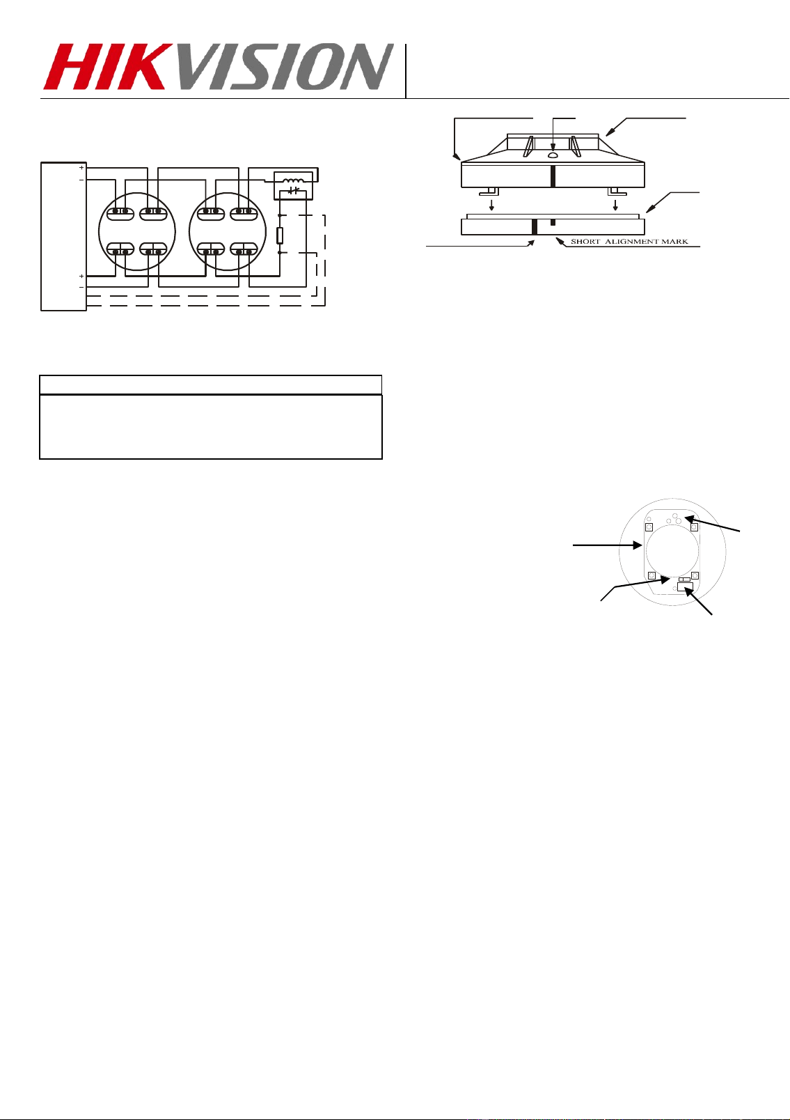
TYPICAL WIRING DIAGRAM
Figure 1 shows the typical wiring diagram of the 4-wire
multiple-station smoke detector system.
FIRST DETECTOR BASE
LAST DETECTOR BASE
POWER
TO
DETECTOR
EN54 LISTED
COMPATIBLE
CONTROL
PANEL
INITIATING
LOOP
CLASS A OPTIONAL WIRING
Fig. 1B Installing the 4-wire multiple station smoke detector base
EOL
POWER
SUPERVISION
RELAY
MODULE
END
OF
LINE
DEVICE
5
2
6 1 3 4
5
2
6 1 3 4
DO NOT PLACE LINKS BETWEEN THE WIRING POSITIONS
OF TERMINALS 2 AND 5 TO PROVIDE POWER
SUPERVISION
WARNING
TO PREVENT DETECTOR CONTAMINATION AND
SUBSEQUENT WARRANTY CANCELLATION, THE
SMOKE DETECTOR MUST REMAIN COVERED UNTIL
THE AREA IS CLEAN AND DUST FREE.
INSTALLING THE BASE
1. To insure proper installation of the detector head to the
base, all the wires should be properly addressed at
installation:
(A) Position all the wires flat against terminals.
(B) Fasten the wires away from connector terminals.
2. If you use a jumper wire to connect the poles of
terminal 2 and 5 when testing the detector loop
continuity, be sure to remove the jumper wire prior to
the installation of the detector head.
3. The end-of-line device shown in fig. 1(a) and 1(b)
should be compatible with the control unit. The
end-of-line supervisory relay used should be rated for
the DC power voltage used.
4. As per EN 54 standard, open area smoke detectors
are intended for mounting on a ceiling no less than
100mm from a wall or mounting on a wall than no less
than 100mm and no more than 300mm from a ceiling.
5. The base of the smoke detector can be mounted
directly onto an electrical junction box such as an
octagonal (75mm, 90mm or 100mm), a round (75mm),
or a square (100mm) box without using any type of
mechanical adapter.
INSTALLING THE HEAD
1. Align the components as shown in Figure 2.
2. Mate the detector head onto the base and twist
clockwise to secure it.
3. Do not install the detector head until the area is
thoroughly cleaned of construction debris, dusts, etc.
The maximum number of smoke detector installed in
the same loop is 30 units.
BASE
DETECTOR HEADLEDRECTANGULAR
OPENING HERE
LONG ALIGNMENT MARK
Fig. 2 Mating detector head onto base
ADJUSTMENT THE RELAY POSITION
ADJUSTING THE RELAY FOR NO/NC
The normal condition for the relay is “normally open”
(NO).
1. To adjust the normal condition of the relay to
“normally closed” (NC), insert a screwdriver into the
rectangular hole located on the side between the front
cover and base and rotate to remove the front cover.
2. Refer to figure 3. There is a jumper head next to the
relay on the PCB. Remove the jumper head and reinsert
it in the NC position.
3. Carefully replace the front cover.
Relay contact Jumper
rating: setting
1A@30VDC,
0.5A@125VAC.
TESTING
1. All the alarm signal services, releasing device and
extinguisher system should be disengaged during the
test period and must be re-engaged immediately at the
conclusion of testing.
2. After energizing the detector head for approximately
one minute, check to see the indicator green LED
flashing once every 4~6 seconds. If green LED fails to
flash, it indicates the non-functioning of the detector or
faulty wiring. Re-check the wiring or replace the
detector if necessary.
3. Allow smoke from a cotton wick or a test smoke
aerosol to enter the detector-sensing chamber for at
least 10 seconds. When sufficient smoke has entered
the chamber, the detector will signal an alarm, this
being visible by a continuous illumination of the LED.
Reset each detector and/or control unit before
attempting to test any additional detectors in the same
zone. If the alarm fails in this step, it indicates a
defective unit, which requires service.
RELAY
CHAMBER
LED
Fig. 3 Schematic of detector structure
When front cover is open.

MAINTENANCE
The recommended minimum requirement for detector
maintenance consists of an annual cleaning of dust from
the detector head by using a vacuum cleaner cleaning
program should be agreed to the individual environment
in conformance with EN 54-7:2000 and EN 54-5:2000
standards.
CAUTION: DO NOT ATTEMPT TO DISASSEMBLY OF
THE FACTORY SEALED SMOKE DETECTOR. THIS
ASSEMBLY IS SEALED FOR YOUR PROTECTION AND
IS NOT INTENDED TO BE OPENED FOR SERVICING BY
USERS. OPENING THE DETECTOR HEAD WILL VOID
THE WARRANTY.
NOT SUITABLE FOR INSTALLATION IN
AREAS WHERE AIR VELOCITIES EXCEED
600 meters/min
LIMITED WARRANTY STATEMENT
Hangzhou Hikvision Digital Technology Co.,Ltd declares that this product is free from defects in material and workmanship. And it will repair or
replace any product or part thereof which proves to be defective in workmanship or material for a period of twelve (12) months from the date of
purchase but not to exceed eighteen (18) months after shipment by the manufacturer. For a full description of HIKVISION’S LIMITED WARRANTY,
which, among other things, limits the duration of warranties of merchantability and fitness for a particular purpose and excludes liability for
consequential damages. Please read the entire LIMITED WARRANTY on the HIKVISION quotation. Acceptance of order and/or original invoice
which will become part of your sales agreement. Please contact HIK VISION directly for a return merchandise authorization (RMA) number before
returning goods to the factory in Ningbo, China, Shipment must be prepaid and HIKVISION will repair or replace your returned detector
Headquarters
No.555 Qianmo Road, Binjiang District,
Hangzhou 310051, China
Tel: +86-571-8807-5998