English
Diagram Reference
Product Information
Specification
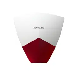
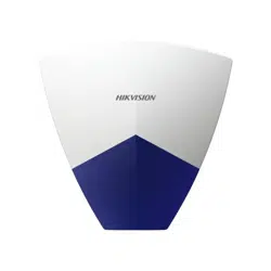
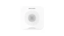
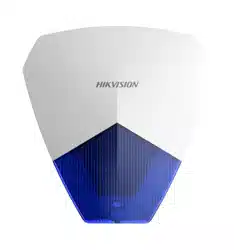
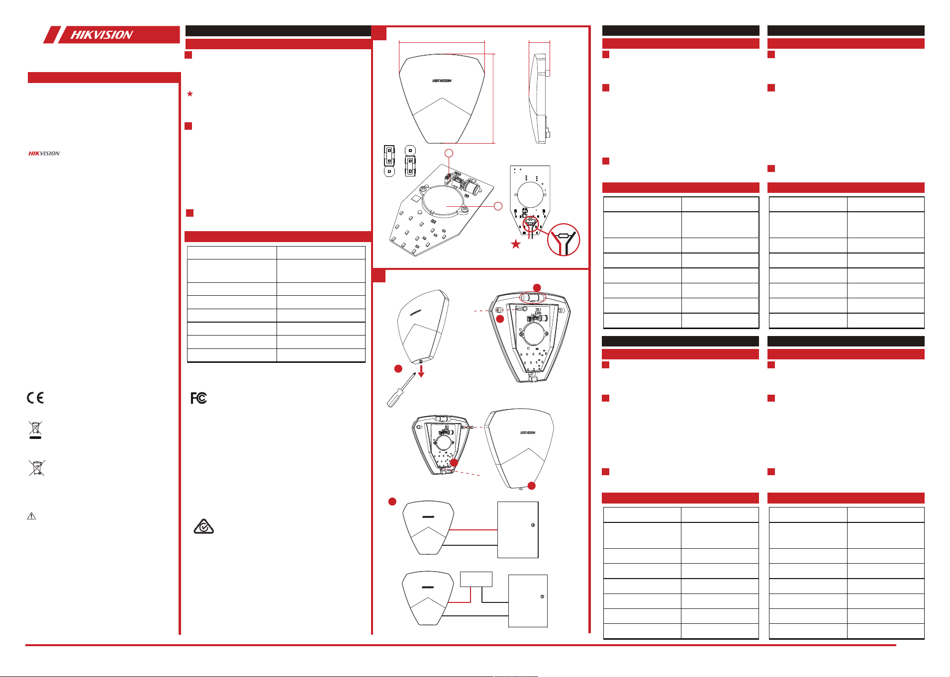
Appearance
1
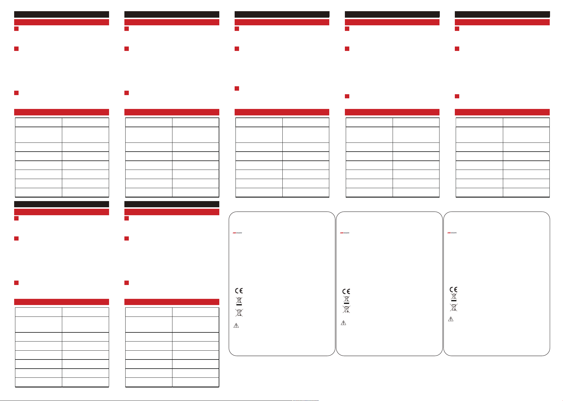
Installation
2.2kΩ
Back
2
1
Wired Sounder
3
Power on
Disclaimer
TO THE MAXIMUM EXTENT PERMITTED BY APPLICABLE LAW,
THIS MANUAL AND THE PRODUCT DESCRIBED, WITH ITS
HARDWARE, SOFTWARE AND FIRMWARE, ARE PROVIDED “AS IS”
AND “WITH ALL FAULTS AND ERRORS”. HIKVISION MAKES NO
WARRANTIES, EXPRESS OR IMPLIED, INCLUDING WITHOUT
LIMITATION, MERCHANTABILITY, SATISFACTORY QUALITY, OR
FITNESS FOR A PARTICULAR PURPOSE. THE USE OF THE PRODUCT
BY YOU IS AT YOUR OWN RISK. IN NO EVENT WILL HIKVISION BE
LIABLE TO YOU FOR ANY SPECIAL, CONSEQUENTIAL, INCIDENTAL,
OR INDIRECT DAMAGES, INCLUDING, AMONG OTHERS,
DAMAGES FOR LOSS OF BUSINESS PROFITS, BUSINESS
INTERRUPTION, OR LOSS OF DATA, CORRUPTION OF SYSTEMS,
OR LOSS OF DOCUMENTATION, WHETHER BASED ON BREACH OF
CONTRACT, TORT (INCLUDING NEGLIGENCE), PRODUCT LIABILITY,
OR OTHERWISE, IN CONNECTION WITH THE USE OF THE
PRODUCT, EVEN IF HIKVISION HAS BEEN ADVISED OF THE
POSSIBILITY OF SUCH DAMAGES OR LOSS.
YOU ACKNOWLEDGE THAT THE NATURE OF THE INTERNET
PROVIDES FOR INHERENT SECURITY RISKS, AND HIKVISION SHALL
NOT TAKE ANY RESPONSIBILITIES FOR ABNORMAL OPERATION,
PRIVACY LEAKAGE OR OTHER DAMAGES RESULTING FROM
CYBER-ATTACK, HACKER ATTACK, VIRUS INFECTION OR OTHER
INTERNET SECURITY RISKS; HOWEVER, HIKVISION WILL PROVIDE
TIMELY TECHNICAL SUPPORT IF REQUIRED.
YOU AGREE TO USE THIS PRODUCT IN COMPLIANCE WITH ALL
APPLICABLE LAWS, AND YOU ARE SOLELY RESPONSIBLE FOR
ENSURING THAT YOUR USE CONFORMS TO THE APPLICABLE LAW.
ESPECIALLY, YOU ARE RESPONSIBLE, FOR USING THIS PRODUCT
IN A MANNER THAT DOES NOT INFRINGE ON THE RIGHTS OF
THIRD PARTIES, INCLUDING WITHOUT LIMITATION, RIGHTS OF
PUBLICITY, INTELLECTUAL PROPERTY RIGHTS, OR DATA
PROTECTION AND OTHER PRIVACY RIGHTS. YOU SHALL NOT USE
THIS PRODUCT FOR ANY PROHIBITED END-USES, INCLUDING THE
DEVELOPMENT OR PRODUCTION OF WEAPONS OF MASS
DESTRUCTION, THE DEVELOPMENT OR PRODUCTION OF
CHEMICAL OR BIOLOGICAL WEAPONS, ANY ACTIVITIES IN THE
CONTEXT RELATED TO ANY NUCLEAR EXPLOSIVE OR UNSAFE
NUCLEAR FUEL-CYCLE, OR IN SUPPORT OF HUMAN RIGHTS
ABUSES.
IN THE EVENT OF ANY CONFLICTS BETWEEN THIS MANUAL AND
THE APPLICABLE LAW, THE LATER PREVAILS.
©2020 Hangzhou Hikvision Digital Technology Co., Ltd. All rights
reserved.
About this Manual
The Manual includes instructions for using and managing the
Product. Pictures, charts, images and all other information
hereinafter are for description and explanation only. The
information contained in the Manual is subject to change,
without notice, due to rmware updates or other reasons. Please
nd the latest version of this Manual at the Hikvision website
(https://www.hikvision.com/).
Please use this Manual with the guidance and assistance of
professionals trained in supporting the Product.
Trademarks
and other Hikvision's trademarks and logos are the
properties of Hikvision in various jurisdictions. Other trademarks
and logos mentioned are the properties of their respective
owners.
1. The additional force shall be equal to three times the
weight of the equipment but not less than 50N. The
equipment and its associated mounting means shall remain
secure during the installation. After the installation, the
equipment, including any associated mounting plate, shall
not be damaged.
2. Install the equipment according to the instructions in this
manual.
3. To prevent injury, this equipment must be securely
attached to the wall in accordance with the installation
instructions.
4. Keep straight down when using the equipment.
5. To prevent possible hearing damage, do not listen at high
volume levels for long periods.
INSTALLATION CAUTION
UD21784B-C
13 4 .0 mm
32 . 7 mm
a
b
4
5
a1 a2
6
Hangzhou Hikvision Digital Technology CO.,Ltd. No.555 Qianmo Road, Binjiang District, Hangzhou 310052, China
14 0 .0 m m
a. Buzzer Control
a1: Silence a2: Voiced
b. Buzzer
Connect a 2.2k-value resistor to the wiring on the
back of the sounder PCB. After connecting the resistor,
the control panel can detect if the wiring of the sounder
is cut.
1. Use a tool to loosen the bottom screw and open the
front and rear panels.
2. Secure one screw.
3. Adjust the installation angle according to the
gradienter.
4. Secure the remaining screws.
5. Tighten the bottom screw to close the front and rear
panels.
6. Wiring to the control panel.
Wiring to the control panel to power on the device.
2006/66/EC (battery directive): This product contains a
battery that cannot be disposed of as unsorted
municipal waste in the European Union. See the product
documentation for specic battery information. The
battery is marked with this symbol, which may include
lettering to indicate cadmium (Cd), lead (Pb), or mercury
(Hg). For proper recycling, return the battery to your
supplier or to a designated collection point. For more
information see:www.recyclethis.info
This product and - if applicable - the supplied accessories
too are marked with "CE" and comply therefore with the
applicable harmonized European standards listed under
the RE Directive 2014/53/EU, the EMC Directive
2014/30/EU, the LVD Directive 2014/35/EU, the RoHS
Directive 2011/65/EU.
2012/19/EU (WEEE directive): Products marked with this
symbol cannot be disposed of as unsorted municipal
waste in the European Union. For proper recycling,
return this product to your local supplier upon the
purchase of equivalent new equipment, or dispose of it
at designated collection points. For more information
see: www.recyclethis.info
FCC statements: This device complies with part 15 of the FCC Rules.
Operation is subject to the following two conditions:(1)this device
may not cause harmful interface, and (2)this device must accept
any interference received,including interference that may cause
undesired operation
FCC Information
Please take attention that changes or modication not expressly approved
by the party responsible for compliance could void the user’s authority to
operate the equipment.
FCC compliance: This equipment has been tested and found to comply with
the limits for a Class A digital device, pursuant to part 15 of the FCC Rules.
These limits are designed to provide reasonable protection against harmful
interference when the equipment is operated in a commercial environment.
This equipment generates, uses, and can radiate radio frequency energy and,
if not installed and used in accordance with the instruction manual, may
cause harmful interference to radio communications. Operation of this
equipment in a residential area is likely to cause harmful interference in
which case the user will be required to correct the interference at his own
expense.
FCC Conditions
This device complies with part 15 of the FCC Rules. Operation is subject to
the following two conditions:
1. This device may not cause harmful interference.
2. This device must accept any interference received, including interference
that may cause undesired operation.
ELECTRICAL SAFETY
1. In the use of the product, you must be in strict compliance with
the electrical safety regulations of the nation and region.
2. The equipment shall not be exposed to dripping or splashing
and that no objects lled with liquids, such as vases, shall be
placed on the equipment.
The power of wired sounder is supplied by the auxiliary power output of
hybrid control panel on the model of DS-PHA64-M, DS-PHA64-W4M. The
auxiliary power supply of the hybrid control panel meets LPS.
2
1
2
3
Model Wired Sounder
Power supply
DC12 V, 0.22 A Max
(Support DC 8 to 16 V)
Static consumption 0.96W
Buzzer 105 dB/30 cm
Operating temperature -20°C to 60°C
Operating humidity 10% to 90%
Dimension 140 × 134 × 33 (mm)
Weight 185g
Warning
This is a class A product. In a domestic environment this
product may cause radio inter-ference in which case the user
may be required to take adequate measures.
Red Line +
Black Line -
Bell+
Bell-
Red Line +
Black Line-
NO
COM/G
DC
12V+
G
OR
Español
Diagrama de referencia
Especificación
1
Apariencia
a. Control del timbre
a1: silencio a2: sonoro
b. Timbre
2
Instalación
1. Utilice una herramienta adecuada para aflojar el tornillo
inferior y abrir los paneles delantero y trasero.
2. Fije el panel trasero colocando uno de los tornillos.
3. Ajuste el ángulo de instalación mediante el nivel.
4. Coloque el tornillo restante.
5. Apriete el tornillo inferior para cerrar los paneles
delantero y trasero.
6. Conecte al panel de control mediante un cable.
3
Encendido
Conecte al panel de control mediante un cable, de manera
de alimentar el dispositivo.
Modelo Sirena cableada
Fuente de alimentación
12 VCC y 0,22 A como máx.
(Admite 8-16 VCC)
Consumo estático 0,96 W
Timbre 105 dB a 30 cm
Temperatura de
funcionamiento
-20 °C a 60 °C
Humedad de
funcionamiento
10 % a 90 %
Dimensiones 140 × 134 × 33 mm
Peso 185 g
Português
Referências do diagrama
Especificações
1
Apresentação
a. Controle da campainha
a1: Silêncio a2: Com voz
b. Campainha
2
Instalação
1. Use uma chave de fenda para afrouxar o parafuso
inferior e abrir os painéis frontal e traseiro.
2. Prenda um parafuso.
3. Ajuste o ângulo de instalação de acordo com o
instrumento de inclinação.
4. Prenda os parafusos restantes.
5. Aperte o parafuso inferior para fechar os painéis frontal
e traseiro.
6. Fiação para o painel de controle.
3
Ligar o painel
Fiação para o painel de controle para ligar o dispositivo.
Modelo Sirene com fio
Fonte de alimentação
12 VCC, 0,22 A máx.
(Suporta CC de 8 a 16 V)
Consumo estático 0,96 W
Campainha 105 dB/30 cm
Temperatura de operação -20 °C a 60°C
Umidade de operação 10% a 90%
Dimensões 140 × 134 × 33 (mm)
Peso 185 g
Čeština
Referenční tabulka
Technické údaje
1
Vzhled
a. Řízení bzučáku
a1: Ticho a2: Znění
b. Bzučák
2
Montáž
1. Pomocí nářadí uvolněte spodní šroub a otevřete přední
a zadní panel.
2. Zajistěte jeden šroub.
3. Pomocí vodováhy nastavte montážní úhel.
4. Zajistěte zbývající šrouby.
5. Utažením spodního šroubu připevněte přední a zadní
panel.
6. Připojte kabeláž k ústředně.
3
Zapnutí
Zařízení se napájí prostřednictvím kabeláže připojené k
ústředně.
Model Kabelová siréna
Napájení
12 V stejnosm., max. 0,22 A
(Podpora 8 až 16 V
stejnosm.)
Statická spotřeba 0,96 W
Bzučák 105 dB / 30 cm
Provozní teplota −20 °C až 60 °C
Provozní vlhkost 10 % až 90 %
Rozměry 140 × 134 × 33 mm
Hmotnost 185 g
Polski
Opis diagramu
Specyfikacje
1
Elementy urządzenia
a. Sterowanie brzęczykiem
a1: Wyciszenie a2: Włączenie
b. Brzęczyk
2
Instalacja
1. Korzystając z narzędzia, poluzuj dolną śrubę, a następnie
otwórz panel przedni i panel tylny.
2. Dokręć jedną śrubę.
3. Dostosuj kąt instalacji przy użyciu poziomicy.
4. Dokręć pozostałe śruby.
5. Dokręć dolną śrubę, aby zamknąć panel przedni i panel
tylny.
6. Podłącz urządzenie do centrali alarmowej.
3
Włączanie zasilania
Aby zapewnić zasilanie urządzenia, należy je podłączyć do
centrali alarmowej.
Model
Przewodowy sygnalizator
akustyczny
Zasilanie
12 V DC, maks. 0,22 A
(obsługa 8–16 V DC)
Pobór mocy 0,96 W
Brzęczyk 105 dB / 30 cm
Temperatura (użytkowanie) Od –20°C do 60°C
Wilgotność powietrza
(użytkowanie)
Od 10% do 90%
Wymiary 140 × 134 × 33 mm
Waga 185 g
© 2020 Hangzhou Hikvision Digital Technology Co., Ltd. Todos los derechos reservados.
Sobre este manual
Este manual incluye las instrucciones de utilización y gestión del producto. Las guras, grácos, imágenes y cualquier otra
información que encontrará en lo sucesivo tienen únicamente nes descriptivos y aclaratorios. La información incluida en el
manual está sujeta a cambios, sin aviso previo, debido a las actualizaciones de software u otros motivos. Visite el sitio web
de Hikvision —https://www.hikvision.com/— para acceder a la última versión de este manual.
Utilice este manual con la guía y asistencia de profesionales capacitados en el soporte del producto.
Marcas registradas
y otras marcas comerciales y logotipos de Hikvision son propiedad de Hikvision en diferentes jurisdicciones. Las
demás marcas comerciales y logotipos mencionados son propiedad de sus respectivos dueños.
Descargo de responsabilidad
EN LA MEDIDA MÁXIMA PERMITIDA POR LAS LEYES APLICABLES, ESTE MANUAL Y EL PRODUCTO DESCRITO —INCLUIDOS SU
HARDWARE, SOFTWARE Y FIRMWARE— SE SUMINISTRAN «TAL CUAL» Y «CON TODOS SU FALLOS Y ERRORES». HIKVISION
NO OFRECE GARANTÍAS, EXPLÍCITAS O IMPLÍCITAS, INCLUIDAS, A MODO ENUNCIATIVO, COMERCIABILIDAD, CALIDAD
SATISFACTORIA O IDONEIDAD PARA UN PROPÓSITO EN PARTICULAR. EL USO QUE HAGA DEL PRODUCTO CORRE BAJO SU
ÚNICO RIESGO. EN NINGÚN CASO, HIKVISION PODRÁ CONSIDERARSE RESPONSABLE ANTE USTED DE NINGÚN DAÑO
ESPECIAL, CONSECUENTE, INCIDENTAL O INDIRECTO, INCLUYENDO, ENTRE OTROS, DAÑOS POR PÉRDIDAS DE BENEFICIOS
COMERCIALES, INTERRUPCIÓN DE LA ACTIVIDAD COMERCIAL, PÉRDIDA DE DATOS, CORRUPCIÓN DE LOS SISTEMAS O
PÉRDIDA DE DOCUMENTACIÓN, YA SEA POR INCUMPLIMIENTO DEL CONTRATO, AGRAVIO (INCLUYENDO NEGLIGENCIA),
RESPONSABILIDAD DEL PRODUCTO O EN RELACIÓN CON EL USO DEL PRODUCTO, INCLUSO CUANDO HIKVISION HAYA
RECIBIDO UNA NOTIFICACIÓN DE LA POSIBILIDAD DE DICHOS DAÑOS O PÉRDIDAS.
USTED RECONOCE QUE LA NATURALEZA DE INTERNET IMPLICA RIESGOS DE SEGURIDAD INHERENTES Y HIKVISION NO
TENDRÁ NINGUNA RESPONSABILIDAD POR EL FUNCIONAMIENTO ANORMAL, FILTRACIONES DE PRIVACIDAD U OTROS
DAÑOS RESULTANTES DE ATAQUES CIBERNÉTICOS, ATAQUES DE HACKERS, INFECCIONES DE VIRUS U OTROS RIESGOS DE
SEGURIDAD DE INTERNET; SIN EMBARGO, HIKVISION PROPORCIONARÁ APOYO TÉCNICO OPORTUNO DE SER NECESARIO.
USTED ACEPTA USAR ESTE PRODUCTO DE CONFORMIDAD CON TODAS LAS LEYES APLICABLES Y SOLO USTED ES EL ÚNICO
RESPONSABLE DE ASEGURAR QUE EL USO CUMPLA CON DICHAS LEYES. EN ESPECIAL, USTED ES RESPONSABLE DE USAR
ESTE PRODUCTO DE FORMA QUE NO INFRINJA LOS DERECHOS DE TERCEROS, INCLUYENDO, DE MANERA ENUNCIATIVA
MAS NO LIMITATIVA, DERECHOS DE PUBLICIDAD, DERECHOS DE PROPIEDAD INTELECTUAL, DERECHOS RELATIVOS A LA
PROTECCIÓN DE DATOS Y OTROS DERECHOS RELATIVOS A LA PRIVACIDAD. NO UTILIZARÁ ESTE PRODUCTO PARA NINGÚN
USO FINAL PROHIBIDO, INCLUYENDO EL DESARROLLO O LA PRODUCCIÓN DE ARMAS DE DESTRUCCIÓN MASIVA, EL
DESARROLLO O PRODUCCIÓN DE ARMAS QUÍMICAS O BIOLÓGICAS, NINGUNA ACTIVIDAD EN EL CONTEXTO RELACIONADO
CON ALGÚN EXPLOSIVO NUCLEAR O EL CICLO DE COMBUSTIBLE NUCLEAR INSEGURO O EN APOYO DE ABUSOS DE LOS
DERECHOS HUMANOS.
EN CASO DE HABER CONFLICTO ENTRE ESTE MANUAL Y LA LEGISLACIÓN VIGENTE, ESTA ÚLTIMA PREVALECERÁ.
Este producto, y, cuando corresponda, también los accesorios suministrados tienen la marca "CE" y por
tanto cumplen con las normas europeas armonizadas aplicables enumeradas en la directiva de equipos de
radio 2014/53/UE, la directiva de compatibilidad electromagnética 2014/30/UE, la directiva de baja
tensión 2014/35/UE y la directiva de restricción del uso de sustancias peligrosas 2011/65/UE.
2012/19/UE (directiva RAEE, residuos de aparatos eléctricos y electromagnéticos): En la Unión Europea,
los productos marcados con este símbolo no pueden ser desechados en el sistema de basura municipal
sin recogida selectiva. Para un reciclaje adecuado, entregue este producto en el lugar de compra del
equipo nuevo equivalente o deshágase de él en el punto de recogida designado a tal efecto. Para ver más
información, visite: www.recyclethis.info
2006/66/CE (directiva sobre baterías): Este producto lleva una batería que no puede ser desechada en el
sistema municipal de basuras sin recogida selectiva dentro de la Unión Europea. Consulte la
documentación del producto para ver la información especíca de la batería. La batería lleva marcado
este símbolo, que incluye unas letras indicando si contiene cadmio (Cd), plomo (Pb), o mercurio (Hg). Para
un reciclaje adecuado, entregue la batería a su vendedor o llévela al punto de recogida de basuras
designado a tal efecto. Para más información visite: www.recyclethis.info.
PRECAUCIONES DE INSTALACIÓN
1. La fuerza adicional debe ser equivalente a tres veces el peso del equipo, pero no inferior a 50 N. El equipo y el
soporte asociado deben permanecer seguros durante la instalación. Tras la instalación, no se debe dañar el equipo
ni tampoco las placas de montaje asociadas.
2. Instale el equipo de acuerdo con las instrucciones de este manual.
3. Con el n de evitar lesiones y, de acuerdo con las instrucciones de instalación, este equipo debe estar
rmemente sujeto a la pared.
4. Al usar el equipo, manténgalo hacia abajo.
5. Para evitar posibles pérdidas de audición, no escuche a volumen alto durante largos periodos de tiempo.
SEGURIDAD ELÉCTRICA
1. Para usar el producto debe cumplir estrictamente con la normativa de seguridad eléctrica de su país y región.
2. No se expondrá el equipo a goteos ni salpicaduras y no se colocarán sobre él objetos llenos de líquidos, como jarrones.
La sirena cableada se alimenta mediante la potencia de salida auxiliar del panel de control híbrido del modelo
DS-PHA64-M, DS-PHA64-W4M. La unidad de alimentación auxiliar del panel de control híbrido es compatible con la fuente
de alimentación de potencia limitada (LPS, por sus siglas en inglés).
Español
©2020 Hangzhou Hikvision Digital Technology Co., Ltd. Todos os direitos reservados.
Acerca deste Manual
O Manual inclui instruções para utilizar e gerir o produto. As fotografias, os gráficos, as imagens e todas as outras
informações doravante apresentadas destinam-se apenas a fins de descritivos e informativos. As informações que constam
do Manual estão sujeitas a alteração, sem aviso prévio, devido a atualizações de firmware ou a outros motivos. Encontre a
versão mais recente deste Manual no site da Hikvision (https://www.hikvision.com/).
Utilize este Manual sob orientação e com a assistência de profissionais formados neste Produto.
Marcas comerciais
e outras marcas registradas e logotipos da Hikvision são propriedade da Hikvision em diversas jurisdições.
Outras marcas comerciais e logótipos mencionados são propriedade dos respetivos proprietários.
Aviso legal
NA MEDIDA MÁXIMA PERMITIDA PELA LEI APLICÁVEL, ESTE MANUAL E O PRODUTO DESCRITO, COM O SEU HARDWARE,
SOFTWARE E FIRMWARE, SÃO FORNECIDOS “TAL COMO ESTÃO” E “COM TODAS AS SUAS FALHAS E ERROS”. A HIKVISION
EXCLUI, DE FORMA EXPLÍCITA OU IMPLÍCITA, GARANTIAS DE, INCLUINDO E SEM LIMITAÇÃO, COMERCIABILIDADE,
QUALIDADE DO SERVIÇO OU ADEQUAÇÃO A UMA FINALIDADE ESPECÍFICA. A SUA UTILIZAÇÃO DESTE PRODUTO É FEITA
POR SUA CONTA E RISCO. EM NENHUMA CIRCUNSTÂNCIA, A HIKVISION SERÁ RESPONSÁVEL POR SI EM RELAÇÃO A
QUAISQUER DANOS ESPECIAIS, CONSEQUENCIAIS, INCIDENTAIS OU INDIRETOS, INCLUINDO, ENTRE OUTROS, DANOS PELA
PERDA DE LUCROS COMERCIAIS, INTERRUPÇÃO DA ATIVIDADE, PERDA DE DADOS, CORRUPÇÃO DE SISTEMAS OU PERDA DE
DOCUMENTAÇÃO SEJA COM BASE NUMA VIOLAÇÃO DO CONTRATO, ATOS ILÍCITOS (INCLUÍNDO NEGLIGÊNCIA),
RESPONSABILIDADE PELO PRODUTO OU, DE OUTRO MODO, RELACIONADA COM A UTILIZAÇÃO DO PRODUTO, AINDA QUE
A HIKVISION TENHA SIDO AVISADA SOBRE A POSSIBILIDADE DE TAIS DANOS OU PERDAS.
O UTILIZADOR RECONHECE QUE A NATUREZA DA INTERNET OFERECE RISCOS DE SEGURANÇA INERENTESE QUE A HIKVISION
NÃO SERÁ RESPONSABILIZADA POR UM FUNCIONAMENTO ANORMAL, PERDA DE PRIVACIDADE OU OUTROS DANOS
RESULTANTES DE ATAQUES INFORMÁTICOS, ATAQUES DE PIRATARIA, INFEÇÃO POR VÍRUS OU OUTROS RISCOS ASSOCIADOS À
SEGURANÇA DA INTERNET. NO ENTANTO, A HIKVISION PRESTARÁ APOIO TÉCNICO ATEMPADO, SE SOLICITADO.
O UTILIZADOR ACEITA UTILIZAR ESTE PRODUTO EM CONFORMIDADE COM TODAS AS LEIS APLICÁVEIS E SER O ÚNICO
RESPONSÁVEL POR GARANTIR QUE A SUA UTILIZAÇÃO É CONFORME À LEI APLICÁVEL. PARTICULARMENTE, O UTILIZADOR É
O RESPONSÁVEL PELA UTILIZAÇÃO DESTE PRODUTO DE MODO QUE NÃO INFRINJA OS DIREITOS DE TERCEIROS, INCLUINDO,
ENTRE OUTROS, OS DIREITOS DE PUBLICIDADE, DIREITOS DE PROPRIEDADE INTELECTUAL OU DE PROTEÇÃO DE DADOS, OU
QUAISQUER OUTROS DIREITOS DE PRIVACIDADE. O UTILIZADOR NÃO PODERÁ UTILIZAR ESTE PRODUTO PARA QUAISQUER
UTILIZAÇÕES FINAIS PROIBIDAS, INCLUINDO O DESENVOLVIMENTO OU PRODUÇÃO DE ARMAS DE DESTRUIÇÃO MACIÇA,
DESENVOLVIMENTO OU PRODUÇÃO DE QUÍMICOS OU ARMAS BIOLÓGICAS, QUAISQUER ATIVIDADES DESENVOLVIDAS NO
ÂMBITO DE EXPLOSIVOS NUCLEARES OU CICLOS DE COMBUSTÍVEL NUCLEAR INSEGURO OU PARA APOIAR ABUSOS AOS
DIREITOS HUMANOS.
NA EVENTUALIDADE DA OCORRÊNCIA DE ALGUM CONFLITO ENTRE ESTE MANUAL E A LEGISLAÇÃO APLICÁVEL, ESTA
ÚLTIMA PREVALECE.
Este produto e, se aplicável, também os acessórios fornecidos estão marcados com "CE" e, portanto, em
conformidade com os padrões europeus harmonizados aplicáveis listados na Diretiva RE 2014/53/EU,
Diretiva EMC 2014/30/EU, Diretiva LVD 2014/35/EU e Diretiva RoHS 2011/65/EU.
2012/19/EU (Diretiva WEEE): os produtos marcados com este símbolo não podem ser descartados como
rejeitos municipais não classicados na União Europeia. Para a reciclagem adequada, retorne este
produto ao seu fornecedor local ao comprar um novo equipamento equivalente ou descarte-o em pontos
de coleta designados. Para obter mais informações, acesse: www.recyclethis.info
2006/66/EC (diretiva sobre baterias): este produto contém uma bateria que não pode ser descartada
como um rejeito municipal não classicado na União Europeia. Rera-se à documentação do produto
para informações especícas sobre baterias. A bateria é marcada com este símbolo, que poderá incluir
letras para indicar cádmio (Cd), chumbo (Pb) ou mercúrio (Hg). Para a reciclagem adequada, devolva a
bateria ao fornecedor ou encaminhe-a a um ponto de coleta designado. Para obter mais informações,
consulte: www.recyclethis.info
CUIDADOS NA INSTALAÇÃO
1. A força adicional deve ser igual a três vezes o peso do equipamento, mas não inferior a 50 N. O equipamento e
seus recursos de montagem associados devem permanecer seguros durante a instalação. Após a instalação, o
equipamento, incluindo qualquer placa de montagem associada, não pode estar danicado.
2. Instale o equipamento de acordo com as instruções neste manual.
3. Para evitar ferimentos, este equipamento deve ser xado rmemente à parede de acordo com as instruções de
instalação.
4. Mantenha na vertical ao usar o equipamento.
5. Para evitar possíveis danos à audição, não ouça em níveis de volume altos por longos períodos.
SEGURANÇA ELÉTRICA
1. Ao usar este produto, é necessário seguir os regulamentos de segurança elétrica da nação e região.
2. O equipamento não deverá car exposto a gotas ou respingos e nenhum objeto com líquido, como um vaso, deverá ser
colocado no equipamento.
A alimentação da sirene com o é fornecida pela saída de alimentação auxiliar do painel de controle híbrido nos modelos
DS-PHA64-M e DS-PHA64-W4M. A fonte de alimentação auxiliar do painel de controle híbrido atende à LPS.
Português
©2020 Hangzhou Hikvision Digital Technology Co., Ltd. Všechna práva vyhrazena.
Informace o tomto návodu
V návodu jsou obsaženy pokyny k používání a obsluze výrobku. Obrázky, schémata, snímky a veškeré ostatní zde uvedené
informace slouží pouze jako popis a vysvětlení. Informace obsažené v tomto návodu podléhají vzhledem k aktualizacím
rmwaru nebo z jiných důvodů změnám bez upozornění. Nejnovější verzi tohoto návodu naleznete na webových stránkách
společnosti Hikvision (https://www.hikvision.com/).
Tento návod používejte s vedením a pomocí odborníků vyškolených v oblasti podpory výrobku.
Ochranné známky
a ostatní ochranné známky a loga společnosti Hikvision jsou vlastnictvím společnosti Hikvision v různých
jurisdikcích. Ostatní ochranné známky a loga uvedené v této příručce jsou majetkem příslušných vlastníků.
Prohlášení o vyloučení odpovědnosti
TATO PŘÍRUČKA A POPISOVANÉ PRODUKTY VČETNĚ PŘÍSLUŠNÉHO HARDWARU, SOFTWARU A FIRMWARU JSOU V
MAXIMÁLNÍM ROZSAHU PŘÍPUSTNÉM PODLE ZÁKONA POSKYTOVÁNY, „JAK STOJÍ A LEŽÍ“, A „SE VŠEMI VADAMI A
CHYBAMI“. SPOLEČNOST HIKVISION NEPOSKYTUJE ŽÁDNÉ VÝSLOVNÉ ANI PŘEDPOKLÁDANÉ ZÁRUKY ZARNUJÍCÍ MIMO JINÉ
PRODEJNOST, USPOKOJIVOU KVALITU NEBO VHODNOST KE KONKRÉTNÍM ÚČELŮM. POUŽÍVÁNÍ TOHOTO PRODUKTU JE NA
VAŠE VLASTNÍ RIZIKO. SPOLEČNOST HIKVISION V ŽÁDNÉM PŘÍPADĚ NENESE ODPOVĚDNOST ZA JAKÉKOLI ZVLÁŠTNÍ,
NÁSLEDNÉ, NÁHODNÉ NEBO NEPŘÍMÉ ŠKODY ZAHRNUJÍCÍ MIMO JINÉ ŠKODY ZE ZTRÁTY OBCHODNÍHO ZISKU, PŘERUŠENÍ
OBCHODNÍ ČINNOSTI NEBO ZTRÁTY DAT, POŠKOZENÍ SYSTÉMŮ NEBO ZTRÁTY DOKUMENTACE V SOUVISLOSTI S
POUŽÍVÁNÍM TOHOTO VÝROBKU BEZ OHLEDU NA TO, ZDA TAKOVÉ ŠKODY VZNIKLY Z DŮVODU PORUŠENÍ SMLOUVY,
OBČANSKOPRÁVNÍHO PŘEČINU (VČETNĚ NEDBALOSTI) ČI ODPOVĚDNOSTI ZA PRODUKT, A TO ANI V PŘÍPADĚ, ŽE
SPOLEČNOST HIKVISION BYLA NA MOŽNOST TAKOVÝCHTO ŠKOD NEBO ZTRÁTY UPOZORNĚNA.
BERETE NA VĚDOMÍ, ŽE INTERNET SVOU PODSTATOU PŘEDSTAVUJE SKRYTÁ BEZPEČNOSTNÍ RIZIKA A SPOLEČNOST
HIKVISION PROTO NEPŘEBÍRÁ ŽÁDNOU ODPOVĚDNOST ZA NESTANDARDNÍ PROVOZNÍ CHOVÁNÍ, ÚNIK OSOBNÍCH ÚDAJŮ
NEBO JINÉ ŠKODY VYPLÝVAJÍCÍ Z KYBERNETICKÉHO ČI HACKERSKÉHO ÚTOKU, NAPADENÍ VIREM NEBO ŠKODY ZPŮSOBENÉ
JINÝMI INTERNETOVÝMI BEZPEČNOSTNÍMI RIZIKY; SPOLEČNOST HIKVISION VŠAK V PŘÍPADĚ POTŘEBY POSKYTNE VČASNOU
TECHNICKOU PODPORU.
SOUHLASÍTE S TÍM, ŽE TENTO PRODUKT BUDE POUŽÍVÁN V SOULADU SE VŠEMI PLATNÝMI ZÁKONY A VÝHRADNĚ
ODPOVÍDÁTE ZA ZAJIŠTĚNÍ, ŽE VAŠE UŽÍVÁNÍ BUDE V SOULADU S PLATNOU LEGISLATIVOU. ODPOVÍDÁTE ZEJMÉNA ZA
POUŽÍVÁNÍ PRODUKTU ZPŮSOBEM, KTERÝ NEPORUŠUJE PRÁVA TŘETÍCH STRAN, COŽ ZAHRNUJE MIMO JINÉ PRÁVO NA
OCHRANU OSOBNOSTI, PRÁVO DUŠEVNÍHO VLASTNICTVÍ NEBO PRÁVO NA OCHRANU OSOBNÍCH ÚDAJŮ A DALŠÍ PRÁVA NA
OCHRANU SOUKROMÍ. TENTO PRODUKT NESMÍTE POUŽÍVAT K JAKÝMKOLI NEDOVOLENÝM KONCOVÝM ÚČELŮM VČETNĚ
VÝVOJE ČI VÝROBY ZBRANÍ HROMADNÉHO NIČENÍ, VÝVOJE NEBO VÝROBY CHEMICKÝCH ČI BIOLOGICKÝCH ZBRANÍ NEBO
JAKÝCHKOLI ČINNOSTÍ SOUVISEJÍCÍCH S JADERNÝMI VÝBUŠNINAMI NEBO NEBEZPEČNÝM JADERNÝM PALIVOVÝM CYKLEM
ČI K PODPOŘE PORUŠOVÁNÍ LIDSKÝCH PRÁV.
V PŘÍPADĚ JAKÉHOKOLI ROZPORU MEZI TÍMTO NÁVODEM A PŘÍSLUŠNÝMI ZÁKONY PLATÍ DRUHÉ ZMÍNĚNÉ.
Tento výrobek, a případně i dodané příslušenství, jsou označeny štítkem „CE“, což znamená, že vyhovují
příslušným harmonizovaným evropským normám uvedeným ve směrnici RE 2014/53/EU, směrnici EMC
2014/30/EU, směrnici LVD 2014/35/EU a směrnici RoHS 2011/65/EU.
Směrnice 2012/19/ES (WEEE): Výrobky označené tímto symbolem nelze v Evropské unii likvidovat
společně s netříděným domovním odpadem. Při zakoupení nového ekvivalentního výrobku tento výrobek
řádně zrecyklujte vrácením svému místnímu dodavateli, nebo jej zlikvidujte odevzdáním v určených
sběrných místech. Další informace naleznete na adrese: www.recyclethis.info
Směrnice 2006/66/ES (týkající se baterií): Tento výrobek obsahuje baterii, kterou nelze v Evropské unii
likvidovat společně s netříděným domovním odpadem. Konkrétní informace o baterii naleznete v
dokumentaci výrobku. Baterie je označena tímto symbolem, který může obsahovat písmena značící
kadmium (Cd), olovo (Pb) nebo rtuť (Hg). Za účelem řádné recyklace baterii odevzdejte svému dodavateli
nebo na určené sběrné místo. Další informace naleznete na adrese: www.recyclethis.info
UPOZORNĚNÍ TÝKAJÍCÍ SE MONTÁŽE
1. Dodatečná síla by měla být rovna trojnásobku hmotnosti zařízení, avšak nejméně 50 N. Zařízení a související
montážní prostředky musejí zůstat během montáže zabezpečeny. Po montáži se zařízení včetně přidružené
montážní desky nesmí poškodit.
2. Namontujte zařízení podle pokynů v tomto návodu.
3. Zařízení je třeba v souladu s montážními pokyny bezpečně připevnit ke stěně, aby nedošlo ke zranění.
4. Při používání zachovávejte svislou polohu zařízení.
5. Neposlouchejte po delší dobu s vysokou hlasitostí, abyste se chránili před možným poškozením sluchu.
ELEKTRICKÁ BEZPEČNOST
1. Při používání výrobku je nutné přísně dodržovat všechny národní a místní předpisy týkající se elektrické bezpečnosti.
2. Zařízení nesmí být vystaveno kapající nebo stříkající vodě a nesmí se na něj pokládat předměty s tekutinami, jako jsou
vázy.
Napájení kabelové sirény je u hybridních modelů ústředen DS-PHA64-M a DS-PHA64-W4M dodáváno prostřednictvím
jejich výstupu pomocného napájení. Výstup pomocného napájení hybridní ústředny splňuje požadavky na omezené zdroje
napájení (LPS).
Čeština
Română
Referinţă diagramă
Specificaţii
1
Aspect
a. Control sonerie
a1: Silenţios a2: Cu voce
b. Sonerie
2
Instalarea
1. Utilizaţi un instrument pentru a slăbi şurubul inferior şi
pentru a deschide panourile din faţă şi din spate.
2. Fixaţi un şurub.
3. Reglaţi unghiul de instalare în funcţie de gradient.
4. Fixaţi şuruburile rămase.
5. Strângeţi şurubul inferior pentru a închide panourile din
faţă şi din spate.
6. Cablarea la panoul de comandă.
3
Pornire
Cablarea la panoul de comandă pentru a porni dispozitivul.
Model Sondă cu fir
Alimentare electrică
C.c. 12 V, Max. 0,22 A
(Acceptă C.c de la 8 până
la 16 V)
Consum static 0,96 W
Sonerie 105 dB/30 cm
Temperatura de funcţionare -20 °C până la 60 °C
Umiditatea de operare De la 10% la 90%
Dimensiuni 140 × 134 × 33 (mm)
Greutate 185 g
Slovenčina
Referenčná schéma
Špecifikácie
1
Vzhľad
a. Ovládanie bzučiaka
a1: Ticho a2: Zvuk
b. Bzučiak
2
Montáž
1. Pomocou nástroja uvoľnite spodnú skrutku a otvorte
predný a zadný panel.
2. Zaistite jednu skrutku.
3. Nastavte uhol montáže podľa daného sklonu.
4. Zaistite zostávajúce skrutky.
5. Utiahnutím spodnej skrutky zatvorte predný a zadný
panel.
6. Zapojte ovládací panel.
3
Zapnutie
Zapojenie ovládacieho panela na zapnutie prístroja.
Model Káblová siréna
Zdroj napájania
Max. DC12 V, 0,22 A
(Podpora DC 8 až 16 V)
Spotreba v statickom stave 0,96 W
Bzučiak
105 dB/30 cm
Prevádzková teplota -20 °C až 60 °C
Prevádzková vlhkosť 10 % až 90 %
Rozmery 140 × 134 × 33 (mm)
Hmotnosť 185 g
Türkçe
Şema Referansı
Özellikler
1
Görünüm
a. Zil Kontrolü
a1: Sessiz a2: Sesli
b. Zil
2
Kurulum
1. Alt vidayı gevşetmek, ön ve arka panelleri açmak için bir
alet kullanın.
2. Bir vidayı sabitleyin.
3. Kurulum açısını eğime göre ayarlayın.
4. Kalan vidaları sabitleyin.
5. Ön ve arka panelleri kapatmak için alt vidayı sıkın.
6. Kontrol paneline kablolama.
3
Gücü Açma
Cihazı açmak için kontrol paneline kablolama.
Model Kablolu Siren
Güç kaynağı
DC12 V, 0.22 A Maks.
(DC 8 ila 16 V destekler)
Statik tüketim 0.96 W
Sesli Sinyal 105 dB/30 cm
Çalışma sıcaklığı -20°C ila 60°C
Çalışma nemi %10 ila %90
Boyut 140 × 134 × 33 (mm)
Ağırlık 185 g
Русский
Пояснения к схемам
Технические данные
1
Внешний вид
a. Механизм управления звонком
a1: Тишина a2: Сигнализация
b. Звонок
2
Установка
1. С помощью отвертки ослабьте винт внизу устройства
и снимите переднюю и заднюю панели.
2. Закрепите устройство с помощью винта.
3. Отрегулируйте положение устройства с помощью
уклономера.
4. Закрепите устройство с помощью оставшихся винтов.
5. Затяните винт снизу, чтобы закрепить переднюю и
заднюю панели.
6. Подключите устройство к панели управления.
3
Включение устройства
Чтобы включить устройство, подключите его к панели
управления.
Модель
Проводная звуковая
сигнализация
Электропитание
12 В пост. тока, макс. 0,22 А
(поддерживается диапазон
от 8 до 16 В пост. тока)
Потребление в
статическом режиме
0,96 Вт
Зуммер 105 дБ/30 см
Рабочая температура От -20 °C до 60 °C
Рабочая влажность 10–90%
Размеры 140 × 134 × 33 мм
Вес 185 г
Ελληνικά
Διάγραμμα αναφοράς
Προδιαγραφές
1
Εμφάνιση
α. Έλεγχος βομβητή
α1: Σίγαση α2: Φωνητική λειτουργία
β. Βομβητής
2
Εγκατάσταση
1. Χρησιμοποιήστε ένα εργαλείο για να ξεβιδώσετε την
κάτω βίδα και ανοίξτε το μπροστινό και το πίσω πλαίσιο.
2. Βιδώστε μία βίδα.
3. Προσαρμόστε τη γωνία εγκατάστασης σύμφωνα με το
αλφάδι.
4. Βιδώστε τις υπόλοιπες βίδες.
5. Σφίξτε την κάτω βίδα για να κλείσετε το μπροστινό και
το πίσω πλαίσιο.
6. Καλωδίωση στον πίνακα ελέγχου.
3
Ενεργοποίηση
Καλωδίωση στον πίνακα ελέγχου για ενεργοποίηση της
συσκευής.
Μοντέλο Ενσύρματη σειρήνα
Ηλεκτρική παροχή
DC12 V, 0,22 A Μέγ.
(Υποστήριξη DC 8 έως 16 V)
Στατική κατανάλωση 0,96 W
Βομβητής 105 dB/30 cm
Θερμοκρασία λειτουργίας -20°C έως 60°C
Υγρασία λειτουργίας 10% έως 90%
Διαστάσεις 140 × 134 × 33 (mm)
Βάρος 185g
Hrvatski
Grafički prikazi
Specifikacija
1
Izgled
a. Kontrola zvučnog signala
a1: Bez zvuka a2: S uključenim zvukom
b. Zvučni signal
2
Postavljanje
1. S pomoću alata otpustite donji vijak i otvorite prednju i
stražnju ploču.
2. Pričvrstite jedan vijak.
3. Podesite kut u skladu s libelom.
4. Pričvrstite preostale vijke.
5. Pričvrstite donji vijak kako biste zatvorili prednju i
stražnju ploču.
6. Povezivanje s kontrolnom pločom.
3
Uključivanje
Povezivanje s kontrolnom pločom kako bi se uređaj
uključio.
Model Žična sirena
Napajanje
DC12 V, 0.22 A Maks.
(Podržava DC 8 do 16 V)
Statička potrošnja 0,96 W
Zvučni signal 105 dB/30 cm
Radna temperatura -20°C do 60°C
Vlažnost 10% do 90%
Dimenzije 140 × 134 × 33 (mm)
Težina 185 g
Slovenščina
Referenčni diagram
Tehnični podatki
1
Videz
a. Gumb brenčala
a1: utišano a2: vklopljeno
b. Brenčalo
2
Namestitev
1. Z orodjem zrahljajte spodnji vijak ter odprite sprednjo in
zadnjo ploščo.
2. Privijte en vijak.
3. Nastavite kot namestitve v skladu z gradienterjem.
4. Privijte preostale vijake.
5. Privijte spodnji vijak, da zaprete sprednjo in zadnjo
ploščo.
6. Priključite na nadzorno ploščo.
3
Vklop
Priključite na nadzorno ploščo, da vklopite napravo.
Model Žični zvočnik
Napajanje
DC12 V, 0,22 A maks.
(Podpora DC 8 do 16 V)
Statična poraba 0,96 W
Brenčalo 105 dB/30 cm
Temperatura delovanja –20 °C do 60 °C
Vlažnost za delovanje Od 10 do 90 %
Dimenzije 140 × 134 × 33 (mm)
Teža 185 g
Ten produkt i ewentualnie dostarczone z nim akcesoria oznaczono symbolem „CE” potwierdzającym
zgodność z odpowiednimi ujednoliconymi normami europejskimi, uwzględnionymi w dyrektywie radiowej
(RE) 2014/53/UE, dyrektywie 2014/30/UE dotyczącej kompatybilności elektromagnetycznej (EMC),
dyrektywie 2014/35/UE dotyczącej sprzętu elektrycznego przewidzianego do stosowania w określonych
granicach napięcia (LVD) oraz dyrektywie 2011/65/UE w sprawie ograniczenia stosowania niektórych
niebezpiecznych substancji w sprzęcie elektrycznym i elektronicznym (RoHS).
Dyrektywa 2012/19/UE w sprawie zużytego sprzętu elektrycznego i elektronicznego (WEEE): Produktów
oznaczonych tym symbolem nie wolno utylizować na obszarze Unii Europejskiej jako niesegregowane
odpady komunalne. Aby zapewnić prawidłowy recykling, należy zwrócić ten produkt do lokalnego
dostawcy przy zakupie równoważnego nowego urządzenia lub utylizować go w wyznaczonym punkcie
selektywnej zbiórki odpadów. Aby uzyskać więcej informacji, skorzystaj ze strony internetowej
www.recyclethis.info.
Dyrektywa 2006/66/WE w sprawie baterii i akumulatorów: Ten produkt zawiera baterię, której nie wolno
utylizować na obszarze Unii Europejskiej jako niesegregowane odpady komunalne. Szczegółowe
informacje dotyczące baterii zamieszczono w dokumentacji produktu. Bateria jest oznaczona tym
symbolem, który może także zawierać litery wskazujące na zawartość kadmu (Cd), ołowiu (Pb) lub rtęci
(Hg). Aby zapewnić prawidłowy recykling, należy zwrócić baterię do dostawcy lub przekazać ją do
wyznaczonego punktu zbiórki. Aby uzyskać więcej informacji, skorzystaj ze strony internetowej
www.recyclethis.info.
PRZESTROGA DOTYCZĄCA INSTALACJI
1. Zazwyczaj uwzględniane jest obciążenie trzykrotnie większe niż ciężar urządzenia, ale nie mniejsze niż 50 N.
Urządzenie i elementy montażowe powinny być zabezpieczone podczas instalacji. Podczas instalacji należy chronić
wyposażenie, takie jak płyta montażowa, przed uszkodzeniem.
2. Urządzenie należy zainstalować zgodnie z instrukcjami podanymi w tym podręczniku.
3. Aby zapobiec zranieniu, należy prawidłowo przymocować urządzenie do ściany zgodnie z instrukcjami
dotyczącymi instalacji.
4. Podczas korzystania z urządzenia powinno być ono ustawione pionowo.
5. Nie wolno słuchać nagrań audio przez dłuższy czas przy wysokim poziomie głośności, ponieważ może to
spowodować uszkodzenie słuchu.
BEZPIECZNE KORZYSTANIE Z WYPOSAŻENIA ELEKTRYCZNEGO
1. Produkt powinien być użytkowany zgodnie z rozporządzeniami dotyczącymi bezpiecznego korzystania z urządzeń
elektrycznych, obowiązującymi w danym kraju lub regionie.
2. Nie wolno dopuścić do rozlania cieczy na urządzeniu. Nie wolno ustawiać na urządzeniu naczyń napełnionych cieczą,
takich jak wazony.
Zasilanie przewodowego sygnalizatora akustycznego jest doprowadzane z wyjścia zasilania pomocniczego hybrydowej
centrali alarmowej w modelach DS-PHA64-M i DS-PHA64-W4M. Zasilanie pomocnicze hybrydowej centrali alarmowej
spełnia wymagania dotyczące źródeł zasilania z własnym ograniczeniem (LPS).
Polski
© 2020 Hangzhou Hikvision Digital Technology Co., Ltd. Wszelkie prawa zastrzeżone.
Opis podręcznika
Podręcznik zawiera instrukcje dotyczące korzystania z produktu i obchodzenia się z nim. Zdjęcia, rysunki, wykresy i
pozostałe informacje zamieszczono w podręczniku wyłącznie dla celów informacyjnych i opisowych. Informacje
zamieszczone w podręczniku mogą ulec zmianie bez powiadomienia w związku z aktualizacjami oprogramowania
układowego lub w innych okolicznościach. Najnowsza wersja tego podręcznika jest dostępna w witrynie internetowej firmy
Hikvision (https://www.hikvision.com/).
Oprócz tego podręcznika należy korzystać z porad i pomocy specjalistów z działu pomocy technicznej związanej z produktem.
Znaki towarowe
oraz inne znaki towarowe i logo Hikvision są własnością firmy Hikvision w różnych jurysdykcjach. Inne znaki
towarowe i logo użyte w podręczniku należą do odpowiednich właścicieli.
Zastrzeżenia prawne
W PEŁNYM ZAKRESIE DOZWOLONYM PRZEZ OBOWIĄZUJĄCE PRAWO TEN PODRĘCZNIK, OPISANY PRODUKT I ZWIĄZANE Z
NIM WYPOSAŻENIE ORAZ OPROGRAMOWANIE APLIKACYJNE I UKŁADOWE SĄ UDOSTĘPNIANE BEZ GWARANCJI. FIRMA
HIKVISION NIE UDZIELA ŻADNYCH WYRAŹNYCH ANI DOROZUMIANYCH GWARANCJI, TAKICH JAK GWARANCJE DOTYCZĄCE
PRZYDATNOŚCI HANDLOWEJ, JAKOŚCI LUB PRZYDATNOŚCI DO OKREŚLONEGO CELU. UŻYTKOWNIK KORZYSTA Z PRODUKTU
NA WŁASNE RYZYKO. NIEZALEŻNIE OD OKOLICZNOŚCI FIRMA HIKVISION NIE PONOSI ODPOWIEDZIALNOŚCI ZA STRATY
SPECJALNE, WYNIKOWE, PRZYPADKOWE LUB POŚREDNIE, TAKIE JAK STRATA OCZEKIWANYCH ZYSKÓW Z DZIAŁALNOŚCI
BIZNESOWEJ, PRZERWY W DZIAŁALNOŚCI BIZNESOWEJ, USZKODZENIE SYSTEMÓW ALBO STRATA DANYCH LUB
DOKUMENTACJI, WYNIKAJĄCE Z NARUSZENIA UMOWY, PRZEWINIENIA (ŁĄCZNIE Z ZANIEDBANIEM), ODPOWIEDZIALNOŚCI
ZA PRODUKT LUB INNYCH OKOLICZNOŚCI, ZWIĄZANE Z UŻYCIEM TEGO PRODUKTU, NAWET JEŻELI FIRMA HIKVISION
ZOSTAŁA POINFORMOWANA O MOŻLIWOŚCI WYSTĄPIENIA TAKICH SZKÓD LUB STRAT.
UŻYTKOWNIK PRZYJMUJE DO WIADOMOŚCI, ŻE KORZYSTANIE Z INTERNETU JEST ZWIĄZANE Z ZAGROŻENIAMI DLA
BEZPIECZEŃSTWA, A FIRMA HIKVISION NIE PONOSI ODPOWIEDZIALNOŚCI ZA NIEPRAWIDŁOWE FUNKCJONOWANIE,
WYCIEK POUFNYCH INFORMACJI LUB INNE SZKODY WYNIKAJĄCE Z ATAKU CYBERNETYCZNEGO, ATAKU HAKERA, DZIAŁANIA
WIRUSÓW LUB INNYCH ZAGROŻEŃ DLA BEZPIECZEŃSTWA W INTERNECIE. FIRMA HIKVISION ZAPEWNI JEDNAK
TERMINOWĄ POMOC TECHNICZNĄ, JEŻELI BĘDZIE TO WYMAGANE.
UŻYTKOWNIK ZOBOWIĄZUJE SIĘ DO KORZYSTANIA Z PRODUKTU ZGODNIE Z OBOWIĄZUJĄCYMI PRZEPISAMI I PRZYJMUJE
DO WIADOMOŚCI, ŻE JEST ZOBOWIĄZANY DO ZAPEWNIENIA ZGODNOŚCI UŻYCIA PRODUKTU Z OBOWIĄZUJĄCYMI
PRZEPISAMI. W SZCZEGÓLNOŚCI UŻYTKOWNIK JEST ZOBOWIĄZANY DO KORZYSTANIA Z PRODUKTU W SPOSÓB, KTÓRY NIE
NARUSZA PRAW STRON TRZECICH, DOTYCZĄCYCH NA PRZYKŁAD WIZERUNKU KOMERCYJNEGO, WŁASNOŚCI
INTELEKTUALNEJ LUB OCHRONY DANYCH I PRYWATNOŚCI. UŻYTKOWNIK NIE BĘDZIE UŻYWAĆ PRODUKTU DO CELÓW
ZABRONIONYCH, TAKICH JAK OPRACOWANIE LUB PRODUKCJA BRONI MASOWEGO RAŻENIA ALBO BRONI CHEMICZNEJ LUB
BIOLOGICZNEJ ORAZ DZIAŁANIA ZWIĄZANE Z MATERIAŁAMI WYBUCHOWYMI NUKLEARNYMI, NIEBEZPIECZNYM CYKLEM
PALIWOWYM LUB ŁAMANIEM PRAW CZŁOWIEKA.
W PRZYPADKU NIEZGODNOŚCI NINIEJSZEGO PODRĘCZNIKA Z OBOWIĄZUJĄCYM PRAWEM, WYŻSZY PRIORYTET BĘDZIE
MIAŁO OBOWIĄZUJĄCE PRAWO.
©2020 Hangzhou Hikvision Digital Technology Co., Ltd. Toate drepturile rezervate.
Despre acest manual
Manualul include instrucţiunile pentru utilizarea şi gestionarea produsului. Fotograile, gracele şi imaginile, precum şi
celelalte informaţii expuse în continuare sunt prezente exclusiv în scop descriptiv şi explicativ. Informaţiile din Manual pot
modicate fără noticare, ca urmare a actualizărilor de rmware sau din alte motive. Vă rugăm să găsiţi cea mai recentă
versiune a acestui manual pe site-ul web Hikvision (https://www.hikvision.com/).
Vă rugăm să utilizaţi acest manual cu îndrumarea şi asistenţa profesioniştilor instruiţi în asistenţa pentru acest produs.
Mărcile comerciale
şi alte mărci comerciale şi logo-uri ale Hikvision sunt proprietăţile Hikvision în diferite jurisdicţii. Alte mărci
comerciale şi logo-uri men ionate reprezintă proprietatea de inătorilor resepctivi.
Declinarea răspunderii legale
ÎN LIMITA LEGII APLICABILE, ACEST MANUAL ŞI PRODUSUL DESCRIS, ÎMPREUNĂ CU HARDWARE-UL, SOFTWARE-UL ŞI
FIRMWARE-UL AFERENTE, SUNT OFERITE „AŞA CUM SUNT” ŞI „CU TOATE DEFEC IUNILE ŞI ERORILE”. HIKVISION NU OFERA
NICIO GARANTIE, NICI IN MOD EXPRES SI NICI IMPLICIT, IN CEEA CE PRIVESTE INCLUSIV, DAR FARA LIMITARE LA
COMERCIABILITATEA, CALITATEA SATISFĂCĂTOARE, SAU UTILITATEA PENTRU UN ANUMIT SCOP. DVS. VEŢI UTILIZA ACEST
PRODUS PE PROPRIUL DVS. RISC. ÎN NICIUN CAZ, HIKVISION NU VA FI RĂSPUNZĂTOARE FA Ă DE DVS. PENTRU ORICE
DAUNE INDIRECTE, INCIDENTALE, SPECIALE, DAUNE PENTRU PIERDEREA PROFITULUI, INTRERUPEREA AFACERII SAU
PIERDEREA DE DATE, DEFECTAREA SISTEMELOR SAU PIERDEREA DOCUMENTA IEI, PE BAZA ÎNCĂLCĂRII CONTRACTULUI,
UNEI INFRAC IUNI (INCLUSIV NEGLIJEN Ă), RĂSPUNDEREA PENTRU PRODUSE SAU PRINTR-UN ALT MOD LEGAT DE
UTILIZAREA PRODUSULUI, CHIAR DACĂ HIKVISION A FOST INFORMATĂ ÎN PREALABIL DESPRE POSIBILITATEA APARI IEI UNOR
ASTFEL DE DAUNE SAU PIERDERI.
SUNTEŢI DE ACORD CĂ INTERNETUL, PRIN NATURA SA, PRESUPUNE RISCURI INERENTE CU PRIVIRE LA SECURITATE, IAR
HIKVISION NU ÎŞI ASUMĂ NICIO RESPONSABILITATE PENTRU OPERARE NESATISFACATOARE, ABATERI PRIVIND
CONFIDENŢIALITATEA SAU ALTE DAUNE REZULTATE ÎN URMA UNUI ATAC CIBERNETIC, ATAC AL HACKERILOR, INFECŢII CU
VIRUŞI SAU ALTOR RISCURI PRIVIND SECURITATEA PE INTERNET; CU TOATE ACESTEA, HIKVISION VA OFERI SUPORT TEHNIC
ÎN TIMP UTIL, DACĂ ESTE NECESAR.
SUNTEŢI I DE ACORD SĂ UTILIZA I ACEST PRODUS ÎN CONFORMITATE CU TOATE LEGILE APLICABILE, DEVENIND
RESPONSABIL PENTRU UTILIZAREA ÎN CONFORMITATECU LEGEA APLICABILĂ. SUNTE I, DE ASEMENEA, RESPONSABIL
PENTRU UTILIZAREA ACESTUI PRODUS FĂRĂ A ÎNCĂLCA DREPTURILE TER ILOR, INCLUSIV, DAR FĂRĂ A SE LIMITA LA
DREPTURILE PUBLICITĂ II, DREPTURILE DE PROPRIETATE INTELECTUALĂ SAU DREPTUL LA PROTEC IA DATELOR ŞI ALTE
DREPTURI PRIVATE. NU UTILIZA I ACEST PRODUS PENTRU UTILIZĂRI FINALE INTERZISE, INCLUSIV DEZVOLTAREA SAU
PRODUC IA DE ARME DE DISTRUGERE ÎN MASĂ, DEZVOLTAREA SAU PRODUC IA DE ARME CHIMICE SAU BIOLOGICE,
ACTIVITĂ I LEGATE DE ORICE EXPLOZIBIL NUCLEAR SAU CICLU DE COMBUSTIBIL NUCLEAR CARE AR PRODUCE LIPSĂ DE
SIGURAN Ă SAU ÎN SPRIJINUL ABUZURILOR ASUPRA DREPTURILOR OMULUI.
ÎN EVENTUALITATEA UNUI CONFLICT ÎNTRE ACEST MANUAL ŞI LEGISLA IA APLICABILĂ, VA AVEA PRIORITATE ULTIMA DINTRE
ACESTEA.
Acest produs şi - după caz - accesoriile furnizate sunt marcate „CE” şi respectă, prin urmare, standardele
europene armonizate aplicabile, enumerate în conformitate cu Directiva 2014/53/UE (Directiva RED),
Directiva 2014/30/UE (Directiva EMC), Directiva 2014/35/UE (LVD), Directiva 2011/65/UE – ROHS.
2012/19/UE (Directiva WEEE): Produsele marcate cu acest simbol nu pot eliminate ca deşeu municipal
nesortat în Uniunea Europeană. Pentru o reciclare adecvată, returna i acest produs furnizorului dvs. local
la achizi ionarea unui nou echipament echivalent sau elimina i-l în punctele de colectare indicate. Pentru
mai multe informaţii, a se vedea: www.recyclethis.info
2006/66/CE (Directiva pentru baterii): Acest produs con ine o baterie care nu poate eliminată ca deşeu
municipal nesortat în Uniunea Europeană. Consulta i documenta ia produsului pentru informa ii specice
cu privire la baterie. Bateria este marcată cu acest simbol, care poate include litere pentru a indica
substan ele cadmiu (Cd), plumb (Pb) sau mercur (Hg). Pentru o reciclare adecvată, returna i bateria
furnizorului dvs. sau la un punct de colectare adecvat. Pentru mai multe informaţii,
consultaţi:www.recyclethis.info
ATENŢIONARE PRIVIND INSTALAREA
1. Forţa suplimentară trebuie să e egală cu de trei ori greutatea echipamentului, dar nu mai puţin de 50 N.
Echipamentul şi mijloacele de montaj asociate trebuie să rămână sigure în timpul instalării. După instalare,
echipamentul, inclusiv orice placă de montaj asociată, nu trebuie deteriorate.
2. Instalaţi echipamentul conform instrucţiunilor din acest manual.
3. Pentru a preveni rănirea, acest echipament trebuie să e montat în maximă siguranţă pe perete, în conformitate
cu instrucţiunile de instalare.
4. Ţineţi drept în jos atunci când utilizaţi echipamentul.
5. Pentru a preveni deteriorarea auzului, nu ascultaţi la niveluri ridicate de volum pentru perioade lungi de timp.
SIGURANţĂ ELECTRICĂ
1. În utilizarea produsului, trebuie să respectaţi cu stricteţe reglementările de siguranţă electrică naţionale şi regionale.
2. Echipamentul nu trebuie să e expus la picurare sau la stropire, astfel că niciun obiect umplut cu lichide, cum ar
vazele, nu trebuie să e plasat pe echipament.
Puterea sunetului cu r este furnizată de puterea auxiliară de ieşire a panoului de comandă hibrid pe modelul
DS-PHA64-M, DS-PHA64-W4M. Sursa auxiliară de alimentare a panoului de control hibrid îndeplineşte LPS.
Română
©2020 Hangzhou Hikvision Digital Technology Co., Ltd. Všetky práva vyhradené.
Informácie o tomto návode
Táto príručka obsahuje pokyny na používanie a správu produktu. Obrázky, grafy, nákresy a všetky ďalšie informácie, ktoré sú
v ňom uvedené, slúžia len na opis a vysvetlenie. Informácie uvedené v návode sa môžu zmeniť bez predchádzajúceho
upozornenia v dôsledku aktualizácií rmvéru alebo iných príčin. Najnovšiu verziu tohto návodu nájdete na webovej stránke
spoločnosti Hikvision (https://www.hikvision.com/).
Používajte tento návod v súlade s pokynmi a radami odborníkov, ktorí sú vyškolení na obsluhu produktu.
Ochranné známky
a iné ochranné známky a logá spoločnosti Hikvision sú vlastníctvom spoločnosti Hikvision v rôznych
jurisdikciách. Iné ochranné známky a logá sú vlastníctvom príslušných majiteľov.
Odmietnutie zodpovednosti
V MAXIMÁLNOM MOŽNOM ROZSAHU, KTORÝ POVOĽUJÚ PRÍSLUŠNÉ PRÁVNE PREDPISY, SA TÁTO PRÍRUČKA A OPÍSANÝ
PRODUKT SPOLU S JEHO HARDVÉROM, SOFTVÉROM A FIRMVÉROM, DODÁVAJÚ V STAVE „AKO SÚ“ A „SO VŠETKÝMI
PORUCHAMI A CHYBAMI“. SPOLOČNOSŤ HIKVISION NEPOSKYTUJE ŽIADNE VÝSLOVNÉ ANI PREDPOKLADANÉ ZÁRUKY,
OKREM INÉHO VRÁTANE ZÁRUKY PREDAJNOSTI, USPOKOJIVEJ KVALITY ALEBO VHODNOSTI NA KONKRÉTNY ÚČEL.
POUŽÍVANIE PRODUKTU JE NA VAŠE VLASTNÉ RIZIKO. SPOLOČNOSŤ HIKVISION V ŽIADNOM PRÍPADE NENESIE
ZODPOVEDNOSŤ ZA ŽIADNE OSOBITNÉ, NÁSLEDNÉ, NÁHODNÉ ALEBO NEPRIAME ŠKODY, OKREM INÉHO VRÁTANE ŠKÔD Z
UŠLÉHO PODNIKATEĽSKÉHO ZISKU, PRERUŠENIA PODNIKANIA, STRATY ÚDAJOV, POŠKODENIA SYSTÉMOV ALEBO STRATY
DOKUMENTÁCIE, ČI UŽ NA ZÁKLADE PORUŠENIA ZMLUVY, PREČINU (VRÁTANE NEDBALOSTI), ZODPOVEDNOSTI ZA
PRODUKT ALEBO INAK V SÚVISLOSTI S POUŽÍVANÍM PRODUKTU, A TO ANI V PRÍPADE, AK BOLA SPOLOČNOSŤ HIKVISION
UPOZORNENÁ NA MOŽNOSŤ TAKÝCHTO ŠKÔD.
UZNÁVATE, ŽE POVAHA INTERNETU UMOŽŇUJE INHERENTNÉ BEZPEČNOSTNÉ RIZIKÁ A SPOLOČNOSŤ HIKVISION NENESIE
ŽIADNU ZODPOVEDNOSŤ ZA NEŠTANDARDNÚ PREVÁDZKU, ÚNIK OSOBNÝCH ÚDAJOV ANI ZA INÉ ŠKODY V DÔSLEDKU
KYBERNETICKÉHO ÚTOKU, HAKERSKÉHO ÚTOKU, VÍRUSOVEJ INFEKCIE ALEBO INÝCH BEZPEČNOSTNÝCH RIZÍK SIETE
INTERNET; V PRÍPADE POTREBY VŠAK SPOLOČNOSŤ HIKVISION POSKYTNE VČASNÚ TECHNICKÚ PODPORU.
SÚHLASÍTE S POUŽÍVANÍM TOHTO PRODUKTU V SÚLADE SO VŠETKÝMI PRÍSLUŠNÝMI ZÁKONMI A NESIETE VÝHRADNÚ
ZODPOVEDNOSŤ ZA ZABEZPEČENIE, ABY VAŠE POUŽÍVANIE BOLO V SÚLADE S PRÍSLUŠNÝMI ZÁKONMI. STE OBZVLÁŠŤ
ZODPOVEDNÍ ZA POUŽÍVANIE TOHTO PRODUKTU SPÔSOBOM, KTORÝ NEPORUŠUJE PRÁVA TRETÍCH STRÁN, OKREM INÉHO
PRÁVA PUBLICITY, PRÁVA DUŠEVNÉHO VLASTNÍCTVA, PRÁVA NA OCHRANU ÚDAJOV A INÉ PRÁVA NA OCHRANU
SÚKROMIA. TENTO PRODUKT NESMIETE POUŽÍVAŤ NA ŽIADNE ZAKÁZANÉ ÚČELY VRÁTANE VÝVOJA ALEBO VÝROBY ZBRANÍ
HROMADNÉHO NIČENIA, VÝVOJA ALEBO VÝROBY CHEMICKÝCH ALEBO BIOLOGICKÝCH ZBRANÍ, AKÝCHKOĽVEK AKTIVÍT V
SÚVISLOSTI S AKOUKOĽVEK JADROVOU VÝBUŠNINOU ALEBO NEBEZPEČNÝM CYKLOM JADROVÉHO PALIVA, ALEBO NA
PODPORU ZNEUŽÍVANIA ĽUDSKÝCH PRÁV.
V PRÍPADE AKÉHOKOĽVEK NESÚLADU MEDZI TOUTO PRÍRUČKOU A PRÍSLUŠNÝMI PRÁVNYMI PREDPISMI MAJÚ PREDNOSŤ
PRÍSLUŠNÉ PRÁVNE PREDPISY.
Tento výrobok a rovnako aj príslušenstvo, ak k nemu bolo dodané, sú označené značkou „CE“, takže sú v
súlade s príslušnými harmonizovanými európskymi normami uvedenými v smernici o rádiových
zariadeniach (RE) 2014/53/EÚ, smernici o elektromagnetickej kompatibilite (EMC) 2014/30/EÚ, smernici o
nízkom napätí (LVD) 2014/35/EU a smernici o obmedzení používania určitých nebezpečných látok v
elektrických a elektronických zariadeniach (RoHS) 2011/65/EÚ.
2012/19/EÚ (smernica o odpade z elektrických a elektronických zariadení): Produkty označené týmto
symbolom sa v rámci Európskej únie nesmú likvidovať spolu s netriedeným komunálnym odpadom. Po
zakúpení ekvivalentného nového zariadenia zrecyklujte produkt tým, že ho odovzdáte miestnemu
dodávateľovi alebo ho zlikvidujete na určených zberných miestach. Ďalšie informácie nájdete na:
www.recyclethis.info
2006/66/ES (smernica o batériách): Tento produkt obsahuje batériu, ktorá sa v rámci Európskej únie
nesmie likvidovať spolu s netriedeným komunálnym odpadom. Konkrétne informácie o batérii nájdete v
dokumentácii produktu. Batéria je označená týmto symbolom, ktorý môže obsahovať písmená označujúce
obsah kadmia (Cd), olova (Pb) alebo ortuti (Hg). Zrecyklujte batériu tým, že ju odovzdáte dodávateľovi
alebo ju zlikvidujete na určenom zbernom mieste. Ďalšie informácie nájdete na: www.recyclethis.info
VÝSTRAHA PRI INŠTALÁCII
1. Dodatočná sila pôsobiaca na zariadenie má dosahovať trojnásobok hmotnosti zariadenia, no nesmie byť menšia
ako 50 N. Zariadenie a príslušné montážne prvky musia byť namontované pevne. Po montáži nesmie dôjsť k
poškodeniu zariadenia ani príslušnej montážnej dosky.
2. Zariadenie nainštalujte podľa pokynov v tejto príručke.
3. Aby sa predišlo zraneniu, musí sa zariadenie bezpečne pripevniť k stene podľa montážnych pokynov.
4. Pri používaní zariadenia sa držte dole.
5. Aby nedošlo k prípadnému poškodeniu sluchu, nepočúvajte dlhodobo zvuk s vysokou hlasitosťou.
ELEKTRICKÁ BEZPEČNOSŤ
1. Pri používaní produktu je potrebné, aby ste dôsledne dodržiavali elektroinštalačné bezpečnostné predpisy platné na
celoštátnej a regionálnej úrovni.
2. Zariadenie nesmie byť vystavené kvapkajúcim ani striekajúcim kvapalinám a na zariadenie sa nesmú umiestňovať žiadne
predmety naplnené kvapalinou, napríklad vázy.
V prípade modelu DS-PHA64-M, DS-PHA64-W4M napájanie káblovej siréne dodáva pomocný výstup napájania z
hybridného ovládacieho panela. Pomocné napájanie hybridného ovládacieho panela spĺňa LPS.
Slovenčina
©2020 Hangzhou Hikvision Digital Technology Co., Ltd. Tüm hakları saklıdır.
Bu Kılavuz hakkında
Kılavuz, Ürünün kullanımı ve yönetimi ile ilgili talimatları içerir. Resimler, çizelgeler, görüntüler ve buradaki diğer tüm bilgiler,
yalnızca tanımlama ve açıklama amaçlıdır. Kılavuzda bulunan bilgiler, yazılım güncellemeleri veya başka nedenlerden dolayı
önceden haber verilmeksizin değiştirilebilir. Bu Kılavuzun en son sürümünü Hikvision web sitesinde
(https://www.hikvision.com/) bulabilirsiniz.
Lütfen bu Kılavuzu, Ürünü destekleme konusunda eğitilmiş profesyonellerin rehberliği ve yardımı ile kullanın.
Ticari Markalar
ve diğer Hikvision'un ticari markaları ve logoları Hikvision'un çeşitli yargı mercilerindeki mülkleridir. Bahsedilen
diğer ticari markalar ve logolar ilgili sahiplerinin mülkiyetindedir.
Yasal Uyarı
YÜRÜRLÜKTEKİ YASALARIN İZİN VERDİĞİ AZAMİ ÖLÇÜDE, BU KILAVUZ VE AÇIKLANAN ÜRÜN, DONANIMI, YAZILIMI VE ÜRÜN
YAZILIMI İLE “OLDUĞU GİBİ” VE “TÜM ARIZALAR VE HATALAR İLE " SAĞLANIR. HIKVISION, SINIRLANDIRMA, TİCARİ
OLABİLİRLİK, MEMNUNİYET KALİTESİ VEYA BELİRLİ BİR AMACA UYGUN OLMAKSIZIN AÇIK VEYA ZIMNİ HİÇBİR GARANTİ
VERMEZ. ÜRÜNÜN SİZİN TARAFINIZDAN KULLANIMI KENDİ SORUMLULUĞUNUZDADIR. HIKVISION HİÇBİR DURUMDA, BU
ÜRÜNÜN KULLANIMI İLE BAĞLANTILI OLARAK, HIKVISION BU TÜR HASARLARIN OLASILIĞI HAKKINDA BİLGİLENDİRİLMİŞ
OLSA BİLE, İŞ KARLARININ KAYBI, İŞ KESİNTİSİ, VERİ KAYBI, SİSTEM KESİNTİSİ, BELGE KAYBI, SÖZLEŞMENİN İHLALİ (İHMAL
DAHİL), ÜRÜN SORUMLULUĞU GİBİ ZARARLAR DA DAHİL OLMAK ÜZERE, ÖZEL, SONUÇSAL, TESADÜFİ VEYA DOLAYLI
ZARARLAR İÇİN SİZE KARŞI SORUMLU OLMAYACAKTIR.
İNTERNETİN DOĞASININ DOĞAL GÜVENLİK RİSKLERİ BARINDIRDIĞINI KABUL EDİYORSUNUZ VE HIKVISION, SİBER SALDIRI,
HACKER SALDIRISI, VİRÜS BULAŞMASI VEYA DİĞER İNTERNET GÜVENLİK RİSKLERİNDEN KAYNAKLANAN ANORMAL
KULLANIM, GİZLİLİK SIZINTISI VEYA DİĞER ZARARLAR İÇİN HERHANGİ BİR SORUMLULUK KABUL ETMEZ; ANCAK, HIKVISION
GEREKİRSE ZAMANINDA TEKNİK DESTEK SAĞLAYACAKTIR.
BU ÜRÜNÜ GEÇERLİ TÜM YASALARA UYGUN OLARAK KULLANMAYI KABUL EDİYORSUNUZ VE KULLANIMINIZIN GEÇERLİ
YASALARA UYGUN OLMASINI SAĞLAMAKTAN YALNIZCA SİZ SORUMLUSUNUZ. ÖZELLİKLE, BU ÜRÜNÜ, SINIRLAMA
OLMAKSIZIN, TANITIM HAKLARI, FİKRİ MÜLKİYET HAKLARI VEYA VERİ KORUMA VE DİĞER GİZLİLİK HAKLARI DA DAHİL
OLMAK ÜZERE ÜÇÜNCÜ TARAFLARIN HAKLARINI İHLAL ETMEYECEK ŞEKİLDE KULLANMAKTAN SİZ SORUMLUSUNUZ. BU
ÜRÜNÜ, KİTLE İMHA SİLAHLARININ GELİŞTİRİLMESİ VEYA ÜRETİMİ, KİMYASAL VEYA BİYOLOJİK SİLAHLARIN GELİŞTİRİLMESİ
VEYA ÜRETİMİ, HERHANGİ BİR NÜKLEER PATLAYICI VEYA GÜVENLİ OLMAYAN NÜKLEER YAKIT DÖNGÜSÜ İLE İLGİLİ
HERHANGİ BİR FAALİYETTE VEYA İNSAN HAKLARI İHLALLERİNİ DESTEKLEMEK DE DAHİL YASAKLANMIŞ SON KULLANIMLAR
İÇİN KULLANAMAZSINIZ.
BU KILAVUZ İLE İLGİLİ YASA ARASINDA HERHANGİ BİR ÇELİŞKİ OLMASI DURUMUNDA, YENİ OLAN GEÇERLİDİR.
Bu ürün ve (varsa) birlikte verilen aksesuarlar "CE" ile işaretlenmiştir ve bu nedenle RE Direkti
2014/53/EU, EMC Direkti 2014/30/EU, LVD Direkti 2014/35/EU, RoHS Direkti 2011/65/EU altında
listelenen geçerli uyumlaştırılmış Avrupa standartlarına uygundur.
2012/19/EU (WEEE direkti): Bu simgeyle işaretlenen ürünler, Avrupa Birliği'nde ayrıştırılmamış belediye
atığı olarak yok edilemez. Doğru geri dönüşüm için, eşdeğer yeni ekipman satın aldıktan sonra bu ürünü
yerel tedarikçinize iade edin veya belirtilen toplama noktalarında imha edin. Daha fazla bilgi için bkz:
www.recyclethis.info
2006/66/EC (pil direkti): Bu ürün, Avrupa Birliği'nde ayrıştırılmamış belediye atığı olarak imha
edilemeyen bir pil içerir. Özel pil bilgileri için ürün belgelerine bakın. Pil, kadmiyum (Cd), kurşun (Pb) veya
cıva (Hg) içerebildiğini belirtmek bu simgeyle işaretlenmiştir. Doğru geri dönüşüm için pili tedarikçinize
veya belirlenmiş bir toplama noktasına iade edin. Daha fazla bilgi için bkz: www.recyclethis.info
MONTAJ DİKKAT
1. Ek kuvvet, ekipmanın ağırlığının üç katına eşit olmalı, ancak 50 N'dan az olmamalıdır. Ekipman ve bağlı montaj
araçları kurulum sırasında güvenli kalmalıdır. Kurulumdan sonra, ilgili montaj plakası da dahil, ekipman hasar
görmemelidir.
2. Ekipmanı bu kılavuzdaki talimatlara göre kurun.
3. Yaralanmaları önlemek için bu ekipman kurulum talimatlarına göre duvara güvenli bir şekilde takılmalıdır.
4. Ekipmanı kullanırken düz tutun.
5. İşitme hasarı olasılığını önlemek için uzun süre yüksek sesle dinlemeyin.
ELEKTRİK GÜVENLİĞİ
1. Ürünün kullanımında ülkenin ve bölgenin elektrik güvenliği düzenlemelerine kesinlikle uymanız gerekir.
2. Ekipman, damlayan veya sıçrayan sıvılara maruz bırakılmamalı ve ekipmanın üzerine vazo gibi içi sıvı dolu nesnelerin
konulmamasına dikkat edilmelidir.
Kablolu sirenin gücü, DS-PHA64-M, DS-PHA64-W4M modelinde hibrid kontrol panelinin yardımcı güç çıkışı tarafından
sağlanır. Hibrit kontrol panelinin yardımcı güç kaynağı LPS’n,n başına gelir.
Türkçe
© Hangzhou Hikvision Digital Technology Co., Ltd., 2020 г. Все права защищены.
О данном руководстве
В Руководстве содержатся инструкции по эксплуатации Изделия. Фотографии, схемы, иллюстрации и прочие материалы
приведены исключительно в качестве описаний и пояснений. Информация, приведенная в Руководстве, может быть изменена
без предварительного уведомления в связи с обновлением микропрограммы или по другим причинам. Используйте
последнюю редакцию Руководства. Ее можно найти на веб-сайте компании Hikvision (https://www.hikvision.com/).
Используйте Руководство под наблюдением специалистов, обученных обслуживанию Изделия.
Торговые марки
и другие товарные знаки и логотипы компании Hikvision являются собственностью компании Hikvision в различных
юрисдикциях. Другиетоварные знаки и логотипы, упоминаемые в Руководстве, являются собственностью соответствующих
владельцев.
Ограничение ответственности
В МАКСИМАЛЬНОЙ СТЕПЕНИ, РАЗРЕШЕННОЙ ДЕЙСТВУЮЩИМ ЗАКОНОДАТЕЛЬСТВОМ, ДАННОЕ РУКОВОДСТВО И ОПИСАНИЕ
ИЗДЕЛИЯ, ВМЕСТЕ С АППАРАТНОЙ ЧАСТЬЮ, ПРОГРАММНЫМ ОБЕСПЕЧЕНИЕМ И ВСТРОЕННОЙ МИКРОПРОГРАММОЙ
ПРЕДОСТАВЛЯЕТСЯ «КАК ЕСТЬ» И «СО ВСЕМИ НЕПОЛАДКАМИ И ОШИБКАМИ». HIKVISION НЕ ДАЕТ НИКАКИХ ЯВНЫХ ИЛИ
ПОДРАЗУМЕВАЕМЫХ ГАРАНТИЙ, В ТОМ ЧИСЛЕ, БЕЗ ОГРАНИЧЕНИЙ, ГАРАНТИЙ ТОВАРНОЙ ПРИГОДНОСТИ,
УДОВЛЕТВОРИТЕЛЬНОГО КАЧЕСТВАИЛИ ПРИГОДНОСТИ ДЛЯ КОНКРЕТНЫХ ЦЕЛЕЙ.ПОТРЕБИТЕЛЬ ИСПОЛЬЗУЕТ ИЗДЕЛИЕ НА
СВОЙ СТРАХ И РИСК. НИ ПРИ КАКИХ ОБСТОЯТЕЛЬСТВАХ КОМПАНИЯ HIKVISION НЕ НЕСЕТ ОТВЕТСТВЕННОСТИ ПЕРЕД
ПОТРЕБИТЕЛЕМ ЗА КАКОЙ-ЛИБО СЛУЧАЙНЫЙ ИЛИ КОСВЕННЫЙ УЩЕРБ, ВКЛЮЧАЯ, СРЕДИ ПРОЧЕГО, УБЫТКИ ИЗ-ЗА ПОТЕРИ
ПРИБЫЛИ, ПЕРЕРЫВОВ В ДЕЯТЕЛЬНОСТИ, ПОТЕРИ ДАННЫХ ИЛИ ДОКУМЕНТАЦИИ, ПОВРЕЖДЕНИЯ СИСТЕМ, БУДЬ ТО ПО
ПРИЧИНЕ НАРУШЕНИЯ ДОГОВОРА, ПРОТИВОПРАВНЫХ ДЕЙСТВИЙ (В ТОМ ЧИСЛЕ ХАЛАТНОСТИ), УЩЕРБА ВСЛЕДСТВИЕ
ИСПОЛЬЗОВАНИЯ ИЗДЕЛИЯ ИЛИ ИНОГО В СВЯЗИ С ИСПОЛЬЗОВАНИЕМ ДАННОГО ИЗДЕЛИЯ, ДАЖЕ ЕСЛИ КОМПАНИИ HIKVISION
БЫЛО ИЗВЕСТНО О ВОЗМОЖНОСТИ ТАКОГО УЩЕРБА.
ПОТРЕБИТЕЛЬ ОСОЗНАЕТ, ЧТО ИНТЕРНЕТ ПО СВОЕЙПРИРОДЕ ЯВЛЯЕТСЯ ИСТОЧНИКОМ ПОВЫШЕННОГО РИСКА БЕЗОПАСНОСТИ
И КОМПАНИЯ HIKVISION НЕ НЕСЕТ ОТВЕТСТВЕННОСТИ ЗА СБОИ В РАБОТЕ ОБОРУДОВАНИЯ, УТЕЧКУ ИНФОРМАЦИИ И ДРУГОЙ
УЩЕРБ, ВЫЗВАННЫЙ КИБЕРАТАКАМИ, ХАКЕРАМИ, ВИРУСАМИ ИЛИ СЕТЕВЫМИ УГРОЗАМИ; ОДНАКО НАША КОМПАНИЯ
ОБЕСПЕЧИВАЕТ СВОЕВРЕМЕННУЮ ТЕХНИЧЕСКУЮ ПОДДЕРЖКУ, ЕСЛИ ЭТО НЕОБХОДИМО.
ПОТРЕБИТЕЛЬ СОГЛАШАЕТСЯ ИСПОЛЬЗОВАТЬ ДАННОЕ ИЗДЕЛИЕ В СООТВЕТСТВИИ СО ВСЕМИ ПРИМЕНИМЫМИЗАКОНАМИ И
НЕСЕТ ЛИЧНУЮ ОТВЕТСТВЕННОСТЬ ЗА СОБЛЮДЕНИЕ ВСЕХ ПРИМЕНИМЫХ ЗАКОНОВ. В ЧАСТНОСТИ, ПОТРЕБИТЕЛЬ НЕСЕТ
ОТВЕТСТВЕННОСТЬ ЗА ИСПОЛЬЗОВАНИЕ ЭТОГО ИЗДЕЛИЯ ТАКИМ СПОСОБОМ, КОТОРЫЙ НЕ НАРУШАЕТ ПРАВА ТРЕТЬИХ ЛИЦ, В
ТОМ ЧИСЛЕ, БЕЗ ОГРАНИЧЕНИЙ, ПРАВА ПУБЛИЧНОСТИ, ИНТЕЛЛЕКТУАЛЬНОЙ СОБСТВЕННОСТИ И ЗАЩИТЫ ДАННЫХ.
ПОТРЕБИТЕЛЬ ОБЯЗУЕТСЯ НЕ ИСПОЛЬЗОВАТЬЭТО ИЗДЕЛИЕ В ЗАПРЕЩЕННЫХ ЦЕЛЯХ, В ТОМ ЧИСЛЕ ДЛЯ РАЗРАБОТКИ ИЛИ
ПРОИЗВОДСТВА ОРУЖИЯ МАССОВОГО УНИЧТОЖЕНИЯ, ХИМИЧЕСКОГО ИЛИ БИОЛОГИЧЕСКОГООРУЖИЯ, ОСУЩЕСТВЛЕНИЯ
КАКОЙ-ЛИБО ДЕЯТЕЛЬНОСТИ В КОНТЕКСТЕ ЯДЕРНОГО ОРУЖИЯ, НЕБЕЗОПАСНЫХ ОПЕРАЦИЙ С ЯДЕРНЫМ ТОПЛИВОМ ИЛИ ДЛЯ
ПОДДЕРЖКИ НАРУШЕНИЙ ПРАВ ЧЕЛОВЕКА.
В СЛУЧАЕРАЗНОЧТЕНИЙ МЕЖДУ НАСТОЯЩИМ РУКОВОДСТВОМ И ДЕЙСТВУЮЩИМ ЗАКОНОДАТЕЛЬСТВОМ, ПОСЛЕДНЕЕ ИМЕЕТ
ПРИОРИТЕТ.
Этот продукт и (если применимо) поставляемые аксессуары имеют маркировку "CE" и соответствуют
применимым согласованным стандартам, перечисленным в Директиве по радиооборудованию
2014/53/EU RE, Директиве по электромагнитной совместимости 2014/30/EU EMC, Директиве по
низковольтному оборудованию 2014/35/EU LVD и Директиве по ограничению использования опасных
веществ 2011/65/EU RoHS.
ДИРЕКТИВА WEEE 2012/19/EU (по утилизации отходов электрического и электронного оборудования):
продукты, отмеченные этим символом, запрещено утилизировать в Европейском союзе в качестве
несортированных муниципальных отходов. Для надлежащей переработки возвратите этот продукт
местному поставщику после покупки эквивалентного нового оборудования или утилизируйте его в
предназначенных для этого пунктах сбора отходов. Для получения дополнительной информации посетите
веб-сайт www.recyclethis.info
Директива 2006/66/EC по обращению с батареями: этот продукт содержит батарею, которую запрещено
утилизировать в Европейском союзе в качестве несортированных муниципальных отходов. Для получения
точной информации о батарее см. документацию к продукту. Маркировка батареи может включать
символы, которые определяют ее химический состав: кадмий (CD), свинец (Pb) или ртуть (Hg). Для
надлежащей утилизации отправьте батарею местному поставщику или утилизируйте ее в специальных
пунктах приема отходов. Для получения дополнительной информации посетите веб-сайт
www.recyclethis.info
МЕРЫ ПРЕДОСТОРОЖНОСТИ ПРИ УСТАНОВКЕ
1. Примечание. Монтажное крепление должно выдерживать трехкратный вес оборудования и действие силы не
менее 50 Н. Оборудование и соответствующие средства монтажа должны быть надежно закреплены во время
установки. После установки осмотрите оборудование и монтажную пластину на предмет повреждений.
2. Установите оборудование в соответствии с инструкциями, приведенными в настоящем руководстве.
3. Во избежание травм устройство следует надежно закрепить на стене согласно инструкциям по установке.
4. Во время эксплуатации устройство должно находиться ровно перпендикулярно полу.
5. Во избежание повреждения органов слуха, не осуществляйте прослушивание на высоких уровнях громкости в
течение длительного времени.
ЭЛЕКТРОБЕЗОПАСНОСТЬ
1. Эксплуатация данного изделия должна выполняться в строгом соответствии с правилами безопасной эксплуатации
электрооборудования, действующими в вашей стране и вашем регионе.
2. Устройство не должно подвергаться воздействию капель и брызг; не допускается ставить на него предметы,
наполненные жидкостью, например, вазы с цветами.
На моделях DS-PHA64-M и DS-PHA64-W4M питание проводной звуковой сигнализации осуществляется через
дополнительный выход питания гибридной панели управления. Дополнительный выход питания гибридной панели
управления соответствует требованиям к источникам питания ограниченной мощности (LPS).
Русский
©2020 Hangzhou Hikvision Digital Technology Co., Ltd. Με επιφύλαξη παντός δικαιώματος.
Πληροφορίες για το παρόν εγχειρίδιο
Το Εγχειρίδιο περιλαμβάνει οδηγίες για τη χρήση και τη διαχείριση του Προϊόντος. Οι φωτογραφίες, τα διαγράμματα, οι
εικόνες και όλες οι άλλες πληροφορίες που ακολουθούν προορίζονται μόνο για περιγραφή και επεξήγηση. Οι
πληροφορίες που περιέχονται στο Εγχειρίδιο υπόκεινται σε αλλαγές, χωρίς προειδοποίηση, λόγω ενημερώσεων
υλικολογισμικού ή για άλλους λόγους. Βρείτε την τελευταία έκδοση αυτού του Εγχειριδίου στον ιστότοπο της Hikvision
(https://www.hikvision.com/).
Συνιστάται να χρησιμοποιήσετε το παρόν Εγχειρίδιο υπό την καθοδήγηση και τη βοήθεια επαγγελματιών εκπαιδευμένων
στην υποστήριξη του Προϊόντος.
Εμπορικά σήματα
Το και άλλα εμπορικά σήματα και λογότυπα της Hikvision αποτελούν ιδιοκτησία της Hikvision σε διάφορες
δικαιοδοσίες. Λοιπά εμπορικά σήματα και λογότυπα που αναφέρονται αποτελούν ιδιοκτησία των αντίστοιχων ιδιοκτητών.
Αποποίηση ευθυνών
ΣΤΟΝ ΜΕΓΙΣΤΟ ΒΑΘΜΟ ΠΟΥ ΕΠΙΤΡΕΠΕΤΑΙ ΑΠΟ ΤΟ ΙΣΧΥΟΝ ΔΙΚΑΙΟ, ΤΟ ΠΑΡΟΝ ΕΓΧΕΙΡΙΔΙΟ ΚΑΙ ΤΟ ΠΡΟΪΟΝ ΠΟΥ
ΠΕΡΙΓΡΑΦΕΤΑΙ, ΜΑΖΙ ΜΕ ΤΟΝ ΥΛΙΚΟ ΕΞΟΠΛΙΣΜΟ, ΤΟ ΛΟΓΙΣΜΙΚΟ ΚΑΙ ΤΟ ΥΛΙΚΟΛΟΓΙΣΜΙΚΟ, ΠΑΡΕΧΟΝΤΑΙ «ΩΣ ΕΧΟΥΝ» ΚΑΙ
«ΜΕ ΟΛΑ ΤΑ ΣΦΑΛΜΑΤΑ ΚΑΙ ΒΛΑΒΕΣ». Η HIKVISION ΔΕΝ ΠΑΡΕΧΕΙ ΕΓΓΥΗΣΕΙΣ, ΡΗΤΕΣ Η ΣΙΩΠΗΡΕΣ,
ΣΥΜΠΕΡΙΛΑΜΒΑΝΟΜΕΝΩΝ ΕΝΔΕΙΚΤΙΚΑ, ΕΜΠΟΡΕΥΣΙΜΟΤΗΤΑΣ, ΙΚΑΝΟΠΟΙΗΤΙΚΗΣ ΠΟΙΟΤΗΤΑΣ, Η ΚΑΤΑΛΛΗΛΟΤΗΤΑΣ ΓΙΑ
ΣΥΓΚΕΚΡΙΜΕΝΟ ΣΚΟΠΟ. Η ΧΡΗΣΗ ΤΟΥ ΠΡΟΪΟΝΤΟΣ ΑΠΟ ΕΣΑΣ ΓΙΝΕΤΑΙ ΜΕ ΔΙΚΟ ΣΑΣ ΚΙΝΔΥΝΟ. ΣΕ ΚΑΜΙΑ ΠΕΡΙΠΤΩΣΗ Η
HIKVISION ΔΕΝ ΕΙΝΑΙ ΥΠΕΥΘΥΝΗ ΑΠΕΝΑΝΤΙ ΣΑΣ ΓΙΑ ΓΙΑ ΟΠΟΙΑΔΗΠΟΤΕ ΕΙΔΙΚΗ, ΑΠΟΘΕΤΙΚΗ, ΣΥΜΠΤΩΜΑΤΙΚΗ Η ΕΜΜΕΣΗ
ΖΗΜΙΑ, ΣΥΜΠΕΡΙΛΑΜΒΑΝΟΜΕΝΩΝ ΜΕΤΑΞΥ ΑΛΛΩΝ, ΖΗΜΙΩΝ ΓΙΑ ΑΠΩΛΕΙΑ ΕΠΙΧΕΙΡΗΜΑΤΙΚΩΝ ΚΕΡΔΩΝ, ΔΙΑΚΟΠΗ
ΕΠΙΧΕΙΡΗΜΑΤΙΚΗΣ ΛΕΙΤΟΥΡΓΙΑΣ Η ΑΠΩΛΕΙΑ ΔΕΔΟΜΕΝΩΝ, ΚΑΤΑΣΤΡΟΦΗ ΣΥΣΤΗΜΑΤΩΝ, Η ΑΠΩΛΕΙΑ ΤΕΚΜΗΡΙΩΣΗΣ, ΒΑΣΕΙ
ΑΘΕΤΗΣΗΣ ΣΥΜΒΑΣΗΣ, ΑΔΙΚΟΠΡΑΞΙΑΣ (ΣΥΜΠΕΡΙΛΑΜΒΑΝΟΜΕΝΗΣ ΤΗΣ ΑΜΕΛΕΙΑΣ), ΕΥΘΥΝΗΣ ΑΠΟΖΗΜΙΩΣΗΣ ΠΡΟΪΟΝΤΟΣ,
Η ΑΛΛΩΣ ΠΩΣ, ΑΚΟΜΗ ΚΑΙ ΕΑΝ Η HIKVISION ΕΧΕΙ ΕΝΗΜΕΡΩΘΕΙ ΓΙΑ ΤΗΝ ΠΙΘΑΝΟΤΗΤΑ ΤΕΤΟΙΩΝ ΖΗΜΙΩΝ Η ΑΠΩΛΕΙΩΝ.
ΑΝΑΓΝΩΡΙΖΕΤΕ ΟΤΙ Η ΦΥΣΗ ΤΟΥ ΔΙΑΔΙΚΤΥΟΥ ΕΝΕΧΕΙ ΕΓΓΕΝΕΙΣ ΚΙΝΔΥΝΟΥΣ ΑΣΦΑΛΕΙΑΣ, ΚΑΙ Η HIKVISION ΔΕΝ
ΑΝΑΛΑΜΒΑΝΕΙ ΟΥΔΕΜΙΑ ΕΥΘΥΝΗ ΓΙΑ ΜΗ ΚΑΝΟΝΙΚΗ ΛΕΙΤΟΥΡΓΙΑ, ΔΙΑΡΡΟΗ ΑΠΟΡΡΗΤΩΝ ΔΕΔΟΜΕΝΩΝ Η ΑΛΛΕΣ ΖΗΜΙΕΣ
ΠΟΥ ΠΡΟΚΥΠΤΟΥΝ ΛΟΓΩ ΚΥΒΕΡΝΟ-ΕΠΙΘΕΣΗΣ, ΕΠΙΘΕΣΗΣ ΧΑΚΕΡ, ΜΟΛΥΝΣΗΣ ΑΠΟ ΙΟ Η ΑΛΛΟΥΣ ΔΙΑΔΙΚΤΥΑΚΟΥΣ ΚΙΝΔΥΝΟΥΣ
ΑΣΦΑΛΕΙΑΣ. ΩΣΤΟΣΟ, Η HIKVISION ΘΑ ΠΑΡΕΧΕΙ ΕΓΚΑΙΡΗ ΤΕΧΝΙΚΗ ΥΠΟΣΤΗΡΙΞΗ, ΕΦ’ ΟΣΟΝ ΑΠΑΙΤΗΘΕΙ.
ΣΥΜΦΩΝΕΙΤΕ ΝΑ ΧΡΗΣΙΜΟΠΟΙΗΣΕΤΕ ΑΥΤΟ ΤΟ ΠΡΟΪΟΝ ΣΕ ΣΥΜΜΟΡΦΩΣΗ ΜΕ ΟΛΟΥΣ ΤΟΥΣ ΙΣΧΥΟΝΤΕΣ ΝΟΜΟΥΣ, ΚΑΙ ΘΑ
ΕΧΕΤΕ ΤΗΝ ΑΠΟΚΛΕΙΣΤΙΚΗ ΕΥΘΥΝΗ ΝΑ ΔΙΑΣΦΑΛΙΖΕΤΕ ΟΤΙ Η ΧΡΗΣΗ ΣΑΣ ΣΥΜΦΩΝΕΙ ΜΕ ΤΟ ΙΣΧΥΟΝ ΔΙΚΑΙΟ. ΕΙΔΙΚΑ, ΕΙΣΤΕ
ΥΠΕΥΘΥΝΟΙ ΓΙΑ ΤΗ ΧΡΗΣΗ ΑΥΤΟΥ ΤΟΥ ΠΡΟΪΟΝΤΟΣ ΜΕ ΤΡΟΠΟ ΠΟΥ ΔΕΝ ΠΑΡΑΒΙΑΖΕΙ ΤΑ ΔΙΚΑΙΩΜΑΤΑ ΤΡΙΤΩΝ ΜΕΡΩΝ,
ΣΥΜΠΕΡΙΛΑΜΒΑΝΟΜΕΝΩΝ ΕΝΔΕΙΚΤΙΚΑ, ΔΙΚΑΙΩΜΑΤΩΝ ΔΗΜΟΣΙΟΤΗΤΑΣ, ΔΙΚΑΙΩΜΑΤΩΝ ΠΝΕΥΜΑΤΙΚΗΣ ΙΔΙΟΚΤΗΣΙΑΣ, Ή
ΠΡΟΣΤΑΣΙΑΣ ΔΕΔΟΜΕΝΩΝ ΚΑΙ ΑΛΛΩΝ ΔΙΚΑΙΩΜΑΤΩΝ ΑΠΟΡΡΗΤΟΥ. ΔΕΝ ΘΑ ΧΡΗΣΙΜΟΠΟΙΗΣΕΤΕ ΑΥΤΟ ΤΟ ΠΡΟΪΟΝ ΓΙΑ
ΟΠΟΙΑΔΗΠΟΤΕ ΑΠΑΓΟΡΕΥΜΕΝΗ ΤΕΛΙΚΗ ΧΡΗΣΗ, ΣΥΜΠΕΡΙΛΑΜΒΑΝΟΜΕΝΗΣ ΤΗΣ ΑΝΑΠΤΥΞΗΣ Η ΠΑΡΑΓΩΓΗΣ ΜΑΖΙΚΗΣ
ΚΑΤΑΣΤΡΟΦΗΣ, ΤΗΣ ΑΝΑΠΤΥΞΗΣ Η ΠΑΡΑΓΩΓΗΣ ΧΗΜΙΚΩΝ Η ΒΙΟΛΟΓΙΚΩΝ ΟΠΛΩΝ, ΤΥΧΟΝ ΔΡΑΣΤΗΡΙΟΤΗΤΩΝ ΣΕ ΠΛΑΙΣΙΟ
ΠΟΥ ΣΧΕΤΙΖΕΤΑΙ ΜΕ ΟΠΟΙΑΔΗΠΟΤΕ ΕΚΡΗΚΤΙΚΑ ΠΥΡΗΝΙΚΗΣ ΕΝΕΡΓΕΙΑΣ Η ΜΗ ΑΣΦΑΛΟΥΣ ΚΥΚΟΛΟΥ ΠΥΡΗΝΙΚΩΝ ΚΑΥΣΙΜΩΝ,
Η ΠΡΟΣ ΥΠΟΣΤΗΡΙΞΗ ΠΑΡΑΒΙΑΣΕΩΝ ΤΩΝ ΑΝΘΡΩΠΙΝΩΝ ΔΙΚΑΙΩΜΑΤΩΝ.
ΣΕ ΠΕΡΙΠΤΩΣΗ ΤΥΧΟΝ ΔΙΕΝΕΞΕΩΝ ΜΕΤΑΞΥ ΤΟΥ ΠΑΡΟΝΤΟΣ ΕΓΧΕΙΡΙΔΙΟΥ ΚΑΙ ΤΗΣ ΙΣΧΥΟΥΣΑ ΝΟΜΟΘΕΣΙΑΣ, ΠΡΟΤΕΡΑΙΟΤΗΤΑ
ΕΧΕΙ Η ΔΕΥΤΕΡΗ.
Το προϊόν και - όπου ισχύει - τα παρεχόμενα εξαρτήματα φέρουν τη σήμανση «CE» και άρα είναι
σύμφωνα με τα ισχύοντα εναρμονισμένα ευρωπαϊκά πρότυπα που αναφέρονται στην Οδηγία RE
2014/53/ΕΕ, την Οδηγία EMC 2014/30/ΕΕ, την Οδηγία LVD 2014/35/ΕΕ, την Οδηγία RoHS 2011/65/ΕΕ.
2012/19/ΕΕ (Οδηγία WEEE): Τα προϊόντα που φέρουν το συγκεκριμένο σύμβολο δεν επιτρέπεται να
απορρίπτονται με τα μη ταξινομημένα δημοτικά απόβλητα στην Ευρωπαϊκή Ένωση. Για σωστή
ανακύκλωση, επιστρέψτε το προϊόν στον τοπικό προμηθευτή, κατά την αγορά αντίστοιχου νέου
εξοπλισμού ή απορρίψτε το σε εγκεκριμένα σημεία συλλογής. Για περισσότερες πληροφορίες:
www.recyclethis.info
2006/66/ΕΚ (Οδηγία περί μπαταριών): Το παρόν προϊόν περιέχει μπαταρία η οποία δεν επιτρέπεται να
απορρίπτεται με τα μη ταξινομημένα δημοτικά απόβλητα στην Ευρωπαϊκή Ένωση. Ανατρέξτε στην
τεκμηρίωση του προϊόντος για συγκεκριμένες πληροφορίες μπαταρίας. Η μπαταρία φέρει το
συγκεκριμένο σύμβολο, το οποίο ενδέχεται να περιλαμβάνει γράμματα που υποδηλώνουν την παρουσία
καδμίου (Cd), μολύβδου (Pb) ή υδραργύρου (Hg). Για σωστή ανακύκλωση, επιστρέψτε την μπαταρία
στον προμηθευτή σας ή σε εγκεκριμένο σημείο συλλογής. Για περισσότερες πληροφορίες:
www.recyclethis.info
ΠΡΟΦΥΛΑΞΗ ΓΙΑ ΤΗΝ ΕΓΚΑΤΑΣΤΑΣΗ
1. Η πρόσθετη δύναμη πρέπει να είναι ίση με τρεις φορές το βάρος του εξοπλισμού, αλλά όχι χαμηλότερη από
50N. Ο εξοπλισμός και τα σχετικά μέσα τοποθέτησής του θα παραμένουν ασφαλή στη διάρκεια της
εγκατάστασης. Μετά την εγκατάσταση, ο εξοπλισμός, συμπεριλαμβανομένης τυχόν σχετικής πλακέτας
τοποθέτησης, δεν θα υποστεί φθορές.
2. Εγκαταστήστε τον εξοπλισμό σύμφωνα με τις οδηγίες σε αυτό το εγχειρίδιο.
3. Για την αποφυγή τραυματισμών, αυτός ο εξοπλισμός πρέπει να είναι στερεωμένος καλά στον τοίχο σύμφωνα
με τις οδηγίες εγκατάστασης.
4. Διατηρείτε κάθετη θέση κατά τη χρήση του εξοπλισμού.
5. Για την αποφυγή πιθανών βλαβών στην ακοή, μην ακούτε σε υψηλά επίπεδα έντασης για μεγάλο χρονικό
διάστημα.
ΗΛΕΚΤΡΙΚΗ ΑΣΦΑΛΕΙΑ
1. Κατά τη χρήση του προϊόντος, οφείλετε να τηρείτε αυστηρά τους κανονισμούς ηλεκτρικής ασφάλειας του κράτους και
της περιοχής σας.
2. Ο εξοπλισμός δεν πρέπει να εκτίθεται σε σταγονίδια ή πίδακες υγρών και δεν πρέπει επίσης να τοποθετούνται πάνω
στον εξοπλισμό αντικείμενα γεμάτα με υγρά, όπως βάζα.
Η ισχύς της ενσύρματης σειρήνας παρέχεται από βοηθητική έξοδο ισχύος υβριδικού πίνακα ελέγχου στο μοντέλο
DS-PHA64-M, DS-PHA64-W4M. Η βοηθητική παροχή ισχύος του υβριδικού πίνακα ελέγχου πληροί το LPS.
Ελληνικά
©2020 Hangzhou Hikvision Digital Technology Co., Ltd. Sva prava pridržana.
O Priručniku
Priručnik uključuje upute za uporabu i upravljanje proizvodom. Slike, dijagrami i sve ostale informacije u daljnjem tekstu
služe samo u svrhu opisa i objašnjenja. Informacije sadržane u ovom Priručniku podložne su izmjeni, bez upozorenja, zbog
ažuriranja ugrađenog softvera ili drugih razloga. Molimo potražite najnoviju verziju ovog priručnika na web stranici
Hikvision (https://www.hikvision.com/).
Molimo koristite ovaj priručnik uz smjernice i pomoć stručnjaka obučenih za podršku proizvodu.
Zaštićeni znakovi
i drugi zaštitni znaci i logotipi tvrtke Hikvision vlasništvo su tvrtke Hikvision u raznim državama. Drugi navedeni
znaci i logotipi u pojedinačnom su vlasništvu.
Odricanje
DO MAKSIMALNOG OBUJMA DOZVOLJENOG PRIMJENJIVIM ZAKONOM, OVAJ PRIRUČNIK I OPISANI PROIZVOD, SA SVOJIM
HARDVEROM, SOFTVEROM I FIRMVEROM DAJU SE „KAKVI JESU“ I „SA SVIM GREŠKAMA I POGREŠKAMA“. HIKVISION NE
DAJE JAMSTVA, IZRIČITA ILI PODRAZUMIJEVANA, UKLJUČUJUĆI BEZ OGRANIČENJA, PRODAJNOST, ZADOVOLJAVAJUĆU
KVALITETU ILI PRILAGODLJIVOST ZA ODREĐENU SVRHU. KORIŠTENJE PROIZVODA NA VLASTITI RIZIK. TVRTKA HIKVISION NI
U KOJEM SLUČAJU NIJE ODGOVORNA ZA BILO KOJU POSEBNU, POSLJEDIČNU, SPOREDNU ILI NEIZRAVNU ŠTETU,
UKLJUČUJUĆI, IZMEĐU OSTALIH, ŠTETU ZA GUBITAK POSLOVNE DOBITI, PREKID POSLOVANJA, ILI GUBITKA PODATAKA,
KORUPCIJE SUSTAVA, ILI GUBITKA DOKUMENTACIJE, BILO TEMELJENO NA POVREDI UGOVORA, DELIKTU (UKLJUČUJUĆI
NEHAJ), ODGOVORNOSTI ZA PROIZVOD, ILI INAČE U VEZI S KORIŠTENJEM PROIZVODA, ČAK I AKO JE HIKVISION BIO
UPOZOREN O MOGUĆNOSTI TAKVIH ŠTETA ILI GUBITKA.
PRIZNAJETE DA PRIRODA INTERNETA PREDSTAVLJA NEPOSREDNE SIGURNOSNE RIZIKE, I HIKVISION NE PREUZIMA NIKAKVU
ODGOVORNOST ZA NEUOBIČAJEN RAD, POVREDU PRIVATNOSTI ILI DRUGE ŠTETE PROIZAŠLE IZ CYBER NAPADA, NAPADA
HAKERA, ZARAZE VIRUSOM, ILI DRUGIH SIGURNOSNIH INTERNETSKIH RIZIKA; MEĐUTIM, HIKVISION ĆE OSIGURATI
PRAVOVREMENU TEHNIČKU PODRŠKU AKO JE POTREBNO.
PRIHVAĆATE KORISTITI OVAJ PROIZVOD U SKLADU SA SVIM PRIMJENJIVIM ZAKONIMA, I VI STE ISKLJUČIVO ODGOVORNI ZA
OSIGURAVANJE DA JE VAŠE KORIŠTENJE U SKLADU SA PRIMJENJIVIM ZAKONOM. POSEBNO STE ODGOVORNI ZA
KORIŠTENJE OVOG PROIZVODA NA NAČIN KOJI NE KRŠI PRAVA TREĆIH STRANA, UKLJUČUJUĆI BEZ OGRANIČENJA, PRAVA
JAVNOSTI, PRAVA INTELEKTUALNOG VLASNIŠTVA, ILI ZAŠTITE PODATAKA I DRUGIH PRAVA PRIVATNOSTI. NE SMIJETE
KORISTITI OVAJ PROIZVOD U BILO KOJE ZABRANJENE KRAJNJE SVRHE, UKLJUČUJUĆI RAZVOJ ILI PROIZVODNJU ORUŽJA ZA
MASOVNO UNIŠTENJE, RAZVOJ ILI PROIZVODNJU KEMIJSKOG ILI BIOLOŠKOG ORUŽJA, BILO KOJE AKTIVNOSTI U KONTEKSTU
POVEZANOM S BILO KAKVIM NUKLEARNIM EKSPLOZIVOM ILI NESIGURNIM NUKLEARNIM GORIVNIM CIKLUSOM, ILI U
PODRŠCI ZLOUPORABI LJUDSKIH PRAVA.
U SLUČAJU BILO KAKVIH SUKOBA IZMEĐU OVOG PRIRUČNIKA I VAŽEĆEG ZAKONA, ZAKON ĆE PREVLADATI.
Ovaj proizvod i – ako je primjenjivo – priloženi dodaci označeni su oznakom „CE” te su stoga u skladu s
primjenjivim usklađenim europskim normama navedenim u Direktivi 2014/53/EU o radijskoj opremi,
Direktivi 2014/30/EU o elektromagnetskoj kompatibilnosti, Direktivi 2014/35/EU o niskom naponu,
Direktivi 2011/65/EU o ograničenju uporabe određenih opasnih tvari u električnoj i elektroničkoj opremi.
Direktivi 2012/19/EU o otpadnoj električnoj i elektroničkoj opremi (OEEO): Proizvodi označeni ovim
simbolom ne mogu se odlagati kao nerazvrstani komunalni otpad u Europskoj uniji. Za pravilnu reciklažu,
vratite ovaj proizvod lokalnom dobavljaču pri kupnji istovjetne nove opreme, ili ga odložite na mjestima
predviđenim za prikupljanje. Za više informacija posjetite: www.recyclethis.info
2006/66/EC (direktiva o baterijama): Ovaj proizvod sadrži bateriju koja se ne može odlagati kao
nerazvrstani komunalni otpad u Europskoj uniji. Pogledajte dokumentaciju proizvoda za određene
informacije o baterijama. Baterija je označena ovim simbolom, što može uključivati slova za označavanje
kadmija (Cd), olova (Pb) ili žive (Hg). Za pravilnu reciklažu, vratite bateriju svom dobavljaču ili na mjesto
predviđeno za odlaganje. Za više informacija posjetite: www.recyclethis.info
UPOZORENJA O POSTAVLJANJU
1. Dodatna sila treba biti jednaka trostrukoj težini opreme, ali ne manja od 50 N. Tijekom postavljanja oprema i
povezana sredstva za postavljanje trebaju ostati sigurni. Nakon postavljanja oprema i sve povezane priključne ploče
ne smiju biti oštećeni.
2. Instalirajte opremu prema uputama u ovom priručniku.
3. Kako biste spriječili ozljede, opremu je potrebno sigurno pričvrstiti na zid u skladu s uputama za postavljanje.
4. Pri upotrebi opreme okrenite ravno prema dolje.
5. Kako biste spriječili moguće oštećenje sluha, nemojte držati uređaj na visokim razinama glasnoće tijekom duljeg
vremena.
ELEKTRIČNA SIGURNOST
1. Pri korištenju proizvoda, morate se strogo pridržavati električnih sigurnosnih propisa u zemlji i regiji.
2. Oprema ne smije biti izložena kapanju ili prskanju i na opremu se ne smiju stavljati predmeti napunjeni tekućinama, kao
što su vaze.
Izvor energije žične sirene jest pomoćni izlaz hibridne kontrolne ploče modela DS-PHA64-M, DS-PHA64-W4M. Pomoćni
izvor energije hibridne upravljačke ploče u skladu je sa zahtjevima u pogledu LPS-a.
Hrvatski
© 2020 Hangzhou Hikvision Digital Technology Co., Ltd. Vse pravice pridržane.
O tem priročniku
Priročnik vsebuje navodila za uporabo izdelka in upravljanje z njim. Slike, razpredelnice, podobe in druge informacije v njem
služijo zgolj opisovanju in pojasnjevanju. Informacije v priročniku se lahko zaradi sistemskoprogramskih posodobitev ali
drugih razlogov spremenijo brez predhodnega obvestila. Najnovejša različica tega priročnika je na voljo na spletnem mestu
Hikvision (https://www.hikvision.com/).
Preberite ta priročnik, ki vsebuje navodila in pomoč strokovnjakov, usposobljenih za delo z izdelkom.
Blagovne znamke
in druge blagovne znamke in logotipi družbe Hikvision so last družbe Hikvision v različnih državah/regijah.
Druge navedene blagovne znamke in logotipi so last njihovih zadevnih lastnikov.
Izjava o omejitvi odgovornosti
TA PRIROČNIK IN OPISANI IZDELEK JE SKUPAJ S STROJNO IN PROGRAMSKO OPREMO TER VDELANO PROGRAMSKO OPREMO
V NAJVEČJI MOŽNI MERI, KI JO DOVOLJUJE VELJAVNA ZAKONODAJA, PRIKAZAN, »TAKŠEN, KOT JE«, IN Z VSEMI »OKVARAMI
IN NAPAKAMI«. DRUŽBA HIKVISION NE PODELJUJE NOBENIH JAMSTEV, TAKO IZRECNIH KOT IMPLICITNIH IN NE DOLOČA
OMEJITEV, USTREZNE KAKOVOSTI ALI PRIMERNOSTI ZA DOLOČEN NAMEN. IZDELEK UPORABLJATE NA LASTNO TVEGANJE.
DRUŽBA HIKVISION V NOBENEM PRIMERU NE ODGOVARJA ZA KAKRŠNO KOLI POSEBNO, POSLEDIČNO, NAKLJUČNO ALI
POSREDNO ŠKODO, MED DRUGIM VKLJUČNO S ŠKODO, NASTALO ZARADI IZGUBE POSLOVNEGA DOBIČKA, PREKINITVE
POSLOVANJA ALI IZGUBE PODATKOV, OKVAR SISTEMOV ALI IZGUBE DOKUMENTACIJE, KRŠITVE POGODBE, ŠKODNEGA
DEJANJA (VKLJUČNO Z MALOMARNOSTJO), ODGOVORNOSTJO ZA IZDELEK ALI ŠKODO, NASTALO V ZVEZI Z UPORABO TEGA
IZDELKA, TUDI ČE JE BILA DRUŽBA HIKVISION OBVEŠČENA O MOŽNOSTI TAKE ŠKODE.
STRINJATE SE, DA INTERNET SAM PO SEBI PREDSTAVLJA VARNOSTNA TVEGANJA, IN DRUŽBA HIKVISION NE PREVZEMA
NOBENIH ODGOVORNOSTI ZA NENAVADNO DELOVANJE, RAZKRIVANJE OSEBNIH PODATKOV ALI DRUGO ŠKODO, NASTALO
ZARADI KIBERNETSKEGA NAPADA, NAPADA HEKERJA, OKUŽBE Z VIRUSOM ALI DRUGIH INTERNETNIH VARNOSTNIH
TVEGANJ; KLJUB TEMU PA DRUŽBA HIKVISION PO POTREBI NUDI PRAVOČASNO TEHNIČNO PODPORO.
STRINJATE SE, DA BOSTE IZDELEK UPORABLJALI V SKLADU Z VELJAVNO ZAKONODAJO IN DA STE SAMI ODGOVORNI, DA
BOSTE IZDELEK UPORABLJALI NA NAČIN, KI JE SKLADEN Z VELJAVNO ZAKONODAJO. PRAV TAKO STE ODGOVORNI, DA BOSTE
IZDELEK UPORABLJALI NA NAČIN, KI NE KRŠI PRAVIC TRETJIH OSEB, VKLJUČNO S PRAVICAMI JAVNOSTI, PRAVICAMI
INTELEKTUALNE LASTNINE IN PRAVICAMI ZA VAROVANJE PODATKOV IN DRUGIMI OSEBNIMI PRAVICAMI, A NE OMEJENO
NANJE. TEGA IZDELKA NI DOVOLJENO UPORABLJATI ZA KATERO KOLI OD PREPOVEDANIH UPORAB, VKLJUČNO Z RAZVOJEM
ALI PROIZVODNJO OROŽJA ZA MNOŽIČNO UNIČENJE, RAZVOJEM ALI PROIZVODNJO KEMIČNIH OZ. BIOLOŠKIH OROŽIJ,
VSEMI DEJAVNOSTMI, POVEZANIMI Z JEDRSKIMI EKSPLOZIVNIMI TELESI ALI NEVARNIMI JEDRSKIMI GORILNIMI CELICAMI
OZ. ZA ZLORABO ČLOVEKOVIH PRAVIC.
V PRIMERU NESKLADJA MED TEM PRIROČNIKOM IN VELJAVNIMI PRAVNIMI PREDPISI VELJAJO SLEDNJI.
Ta izdelek in priloženi dodatki (če so na voljo) so označeni z oznako »CE« in so tako skladni z ustreznimi
usklajenimi evropskimi standardi, ki jih navajajo Direktiva RE 2014/53/EU, Direktiva EMC 2014/30/EU,
Direktiva o nizki napetosti 2014/35/EU in Direktiva RoHS 2011/65/EU.
2012/19 / EU (direktiva OEEO): Izdelkov, označenih s tem simbolom, v Evropski uniji ni mogoče odstraniti
kot nesortirane komunalne odpadke. Za pravilno recikliranje vrnite izdelek vašemu lokalnemu dobavitelju
ob nakupu enakovredne nove opreme ali ga odnesite na za to določeno zbirno mesto. Več informacij
najdete na spletnem mestu: www.recyclethis.info
2006/66/EC (direktiva o baterijah): Ta izdelek vsebuje baterijo, ki je v Evropski uniji ni mogoče odstraniti
kot nesortiran komunalni odpadek. Za podatke o baterijah glejte dokumentacijo izdelka. Baterija je
označena s tem simbolom, ki lahko vključuje napis za označevanje kadmija (Cd), svinca (Pb) ali živega
srebra (Hg). Za pravilno recikliranje baterijo vrnite dobavitelju ali na določeno zbirno mesto. Več
informacij najdete na spletnem mestu www.recyclethis.info
POZOR! NAMESTITEV
1. Dodatna sila mora biti enaka trikratni teži opreme, vendar ne manjša od 50 N. Poskrbite, da med namestitvijo ne
poškodujete opreme in priloženih vgradnih pripomočkov. Po končani namestitvi pazite, da ne poškodujete opreme
in morebitne vgradne plošče.
2. Opremo namestite v skladu z navodili v tem priročniku.
3. Da preprečite poškodbe, mora biti oprema trdno nameščena na steno v skladu z navodili za namestitev.
4. Med uporabo opreme naj bo ta obrnjena naravnost navzdol.
5. Da preprečite morebitno poškodbo sluha, ne poslušajte vsebine pri visoki glasnosti dlje časa.
ELEKTRIČNA VARNOST
1. Pri uporabi izdelka morate biti strogo v skladu z narodnimi in regijskimi predpisi električne varnosti.
2. Oprema ne sme biti izpostavljena kapljanju ali pljuskanju in na opremo ne smete postavljati predmetov, napolnjenih s
tekočino, kot so vaze.
Napajanje žičnega zvočnika se dovaja preko pomožnega napajanega izhoda hibridne nadzorne plošče pri modelu
DS-PHA64-M, DS-PHA64-W4M. Pomožno napajanje hibridne nadzorne plošče izpolnjuje zahteve standarda LPS.
Slovenščina