Wired Seismic Detector
DS-PDSKM-VG3
User Manual
EN 50131-2-8 2016
Environment Class II
Security Grade3
Hangzhou Hikvision Digital Technology CO.,Ltd. No.555 Qianmo Road, Binjiang District, Hangzhou 310052, China
=
ALARMTAMPER
+-
EOLEOL
FAULT
5K6 4K7 2K2 1K
LED
5K8 2K2 1K 5K6 4K7 2K2 1K6K8
RF RT RA
2.2K
ALARMTAMPER
+-
EOLEOL
FAULTLED
=
ALARMTAMPER
+-
EOLEOL
FAULT
5K6 4K7 2K2 1K
LED
5K8 2K2 1K
6K8 5K6 4K7 2K2 1K
RF RT RA
2.2K
ALARMTAMPER
+-
EOLEOL
FAULTLED
ALARMTAMPER
+-
EOLEOL
FAULTLED
RF RART
I II
1
6
2
3
a
b
a
b
b
c
4
5
7
A
B
C
=
ALARMTAMPER
+-
EOLEOL
FAULT
5K6 4K7 2K2 1K
LED
5K8 2K2 1K
6K8 5K6 4K7 2K2 1K
RF RT RA
2.2K
ALARMTAMPER
+-
EOLEOL
FAULTLED
a
ZONE2COM ZONE1COM
+ -
ZONE3COM
2.2k
2.2k
ALARMTAMPER +-
EOLEOL
FAULT
5K6 4K7 2K2 1K
LED
5K8 2K2 1K 6K8 5K6 4K7 2K2 1K
RF RT RA
2.2k
2.2k
2.2k
ZONE2COM ZONE1COM
+ -
ZONE3COM
ALARMTAMPER +-
EOLEOL
FAULT
5K6 4K7 2K2 1K
LED
5K8 2K2 1K 6K8 5K6 4K7 2K2 1K
RF RT RA
a
b
c
d
ZONE2COM ZONE1COM
+ -
ZONE3COM
ALARMTAMPER +-
EOLEOL
FAULT
5K6 4K7 2K2 1K
LED
5K8 2K2 1K 6K8 5K6 4K7 2K2 1K
RF RT RA
ZONE2COM ZONE1COM
+ -
ZONE3COM
ALARMTAMPER +-
EOLEOL
FAULT
5K6 4K7 2K2 1K
LED
5K8 2K2 1K 6K8 5K6 4K7 2K2 1K
RF RT RA
7. Tamper Button
Alarm: Solid Blue for 3s
Flashing Red
English
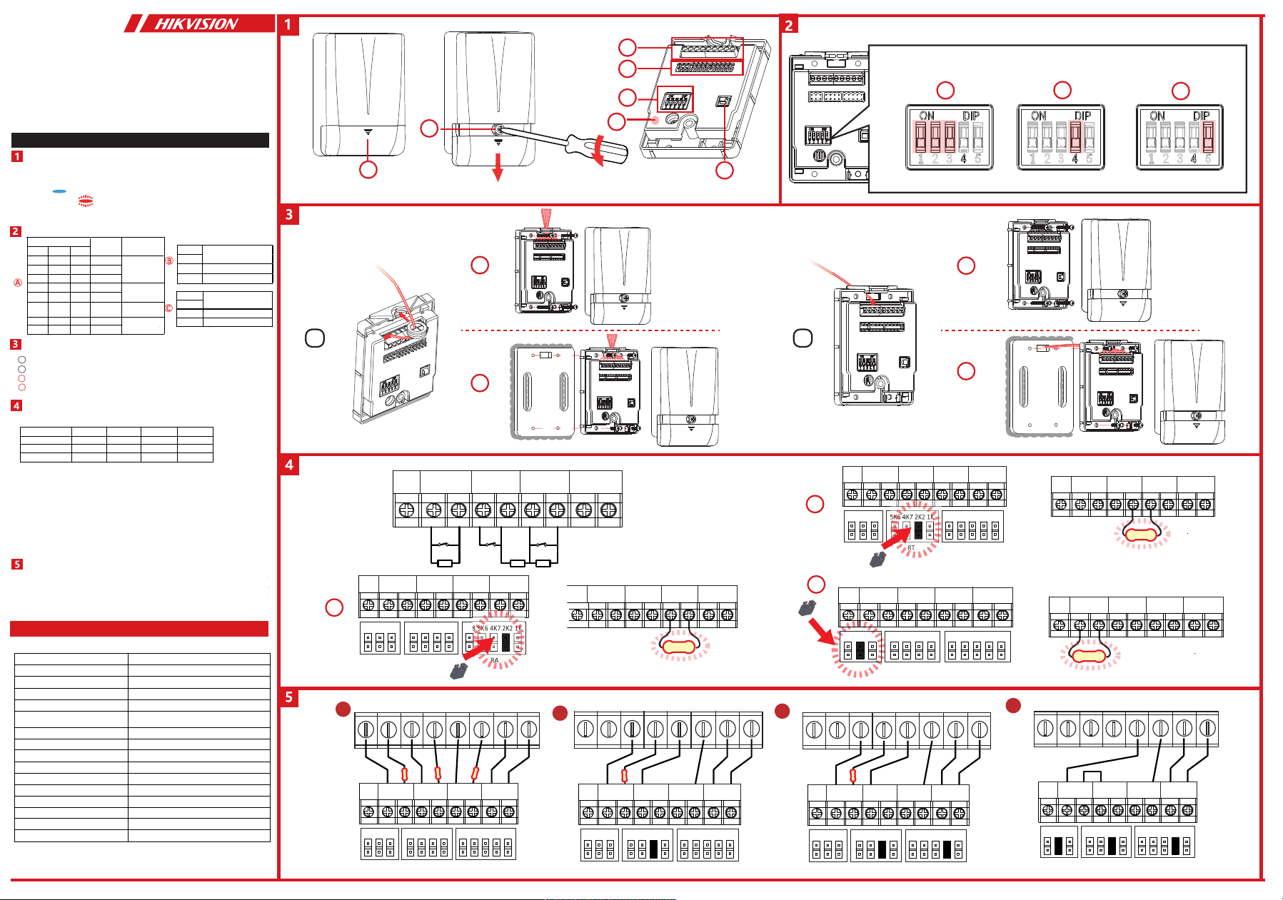
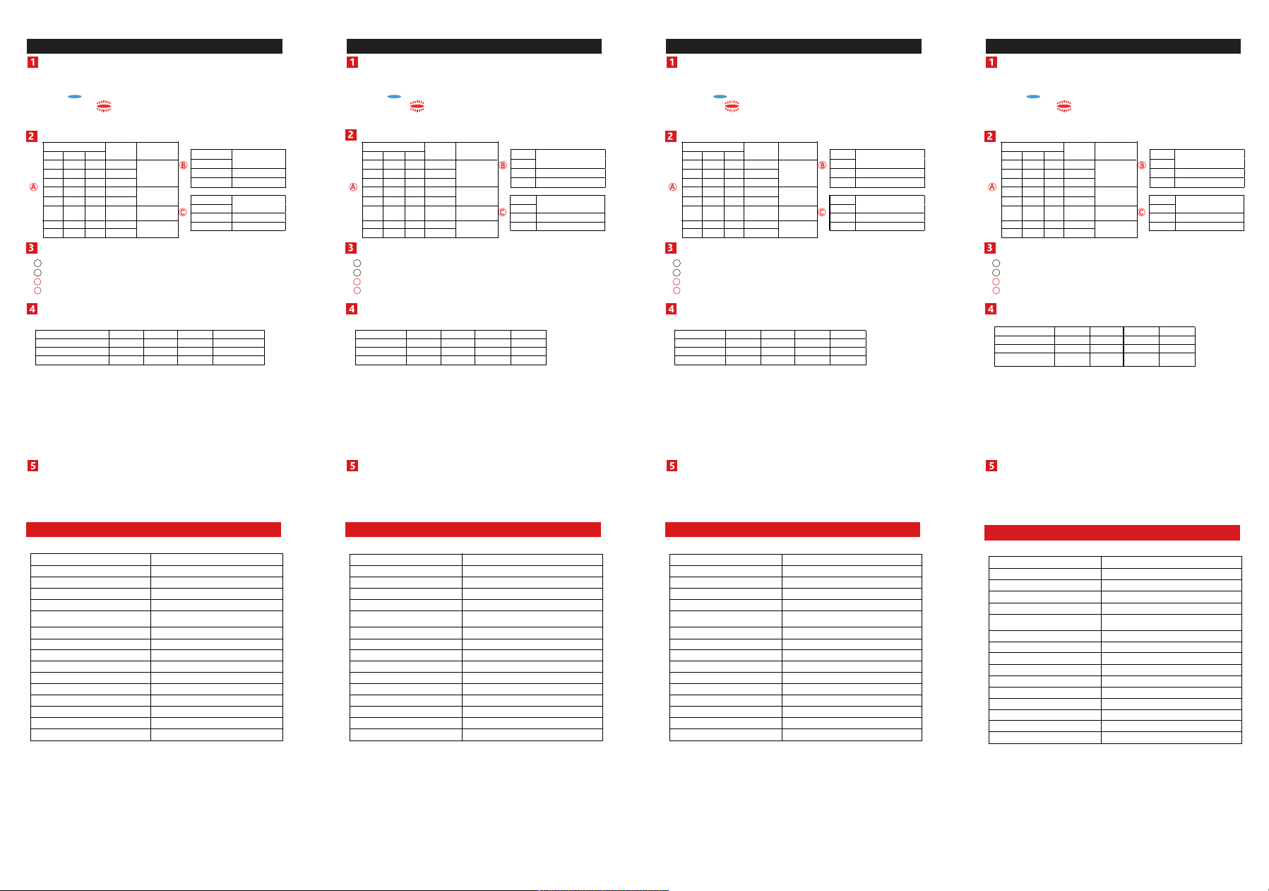
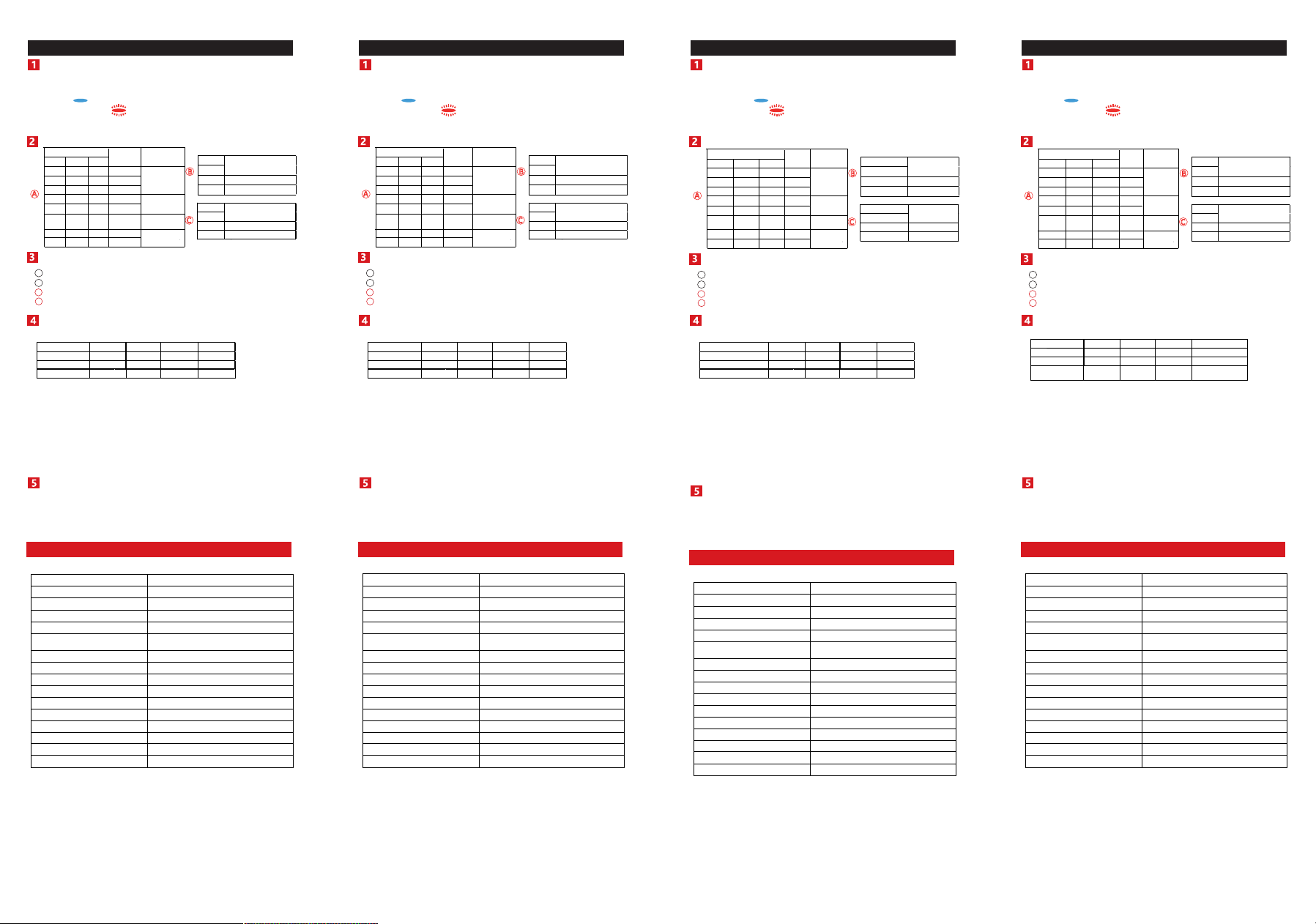
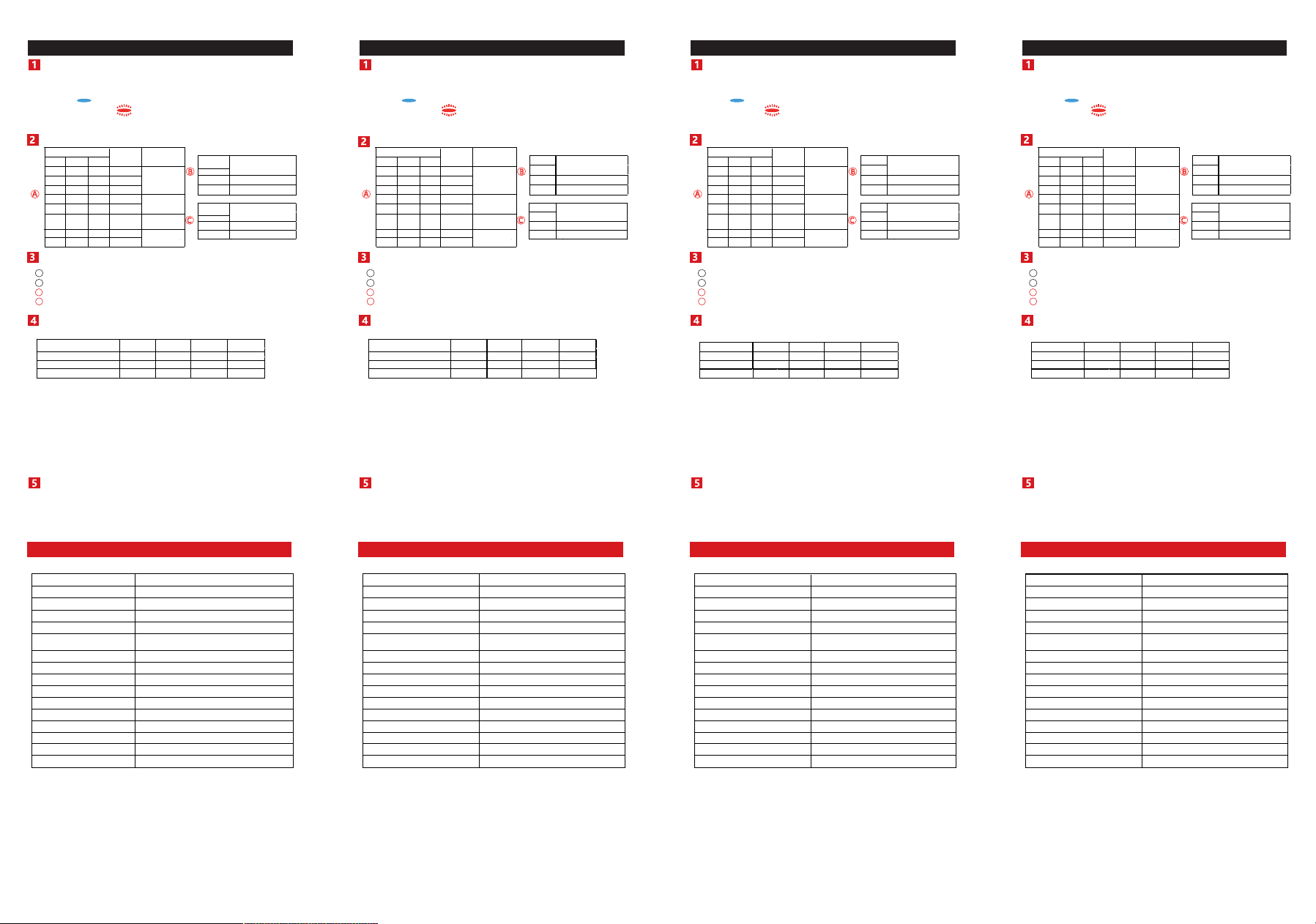
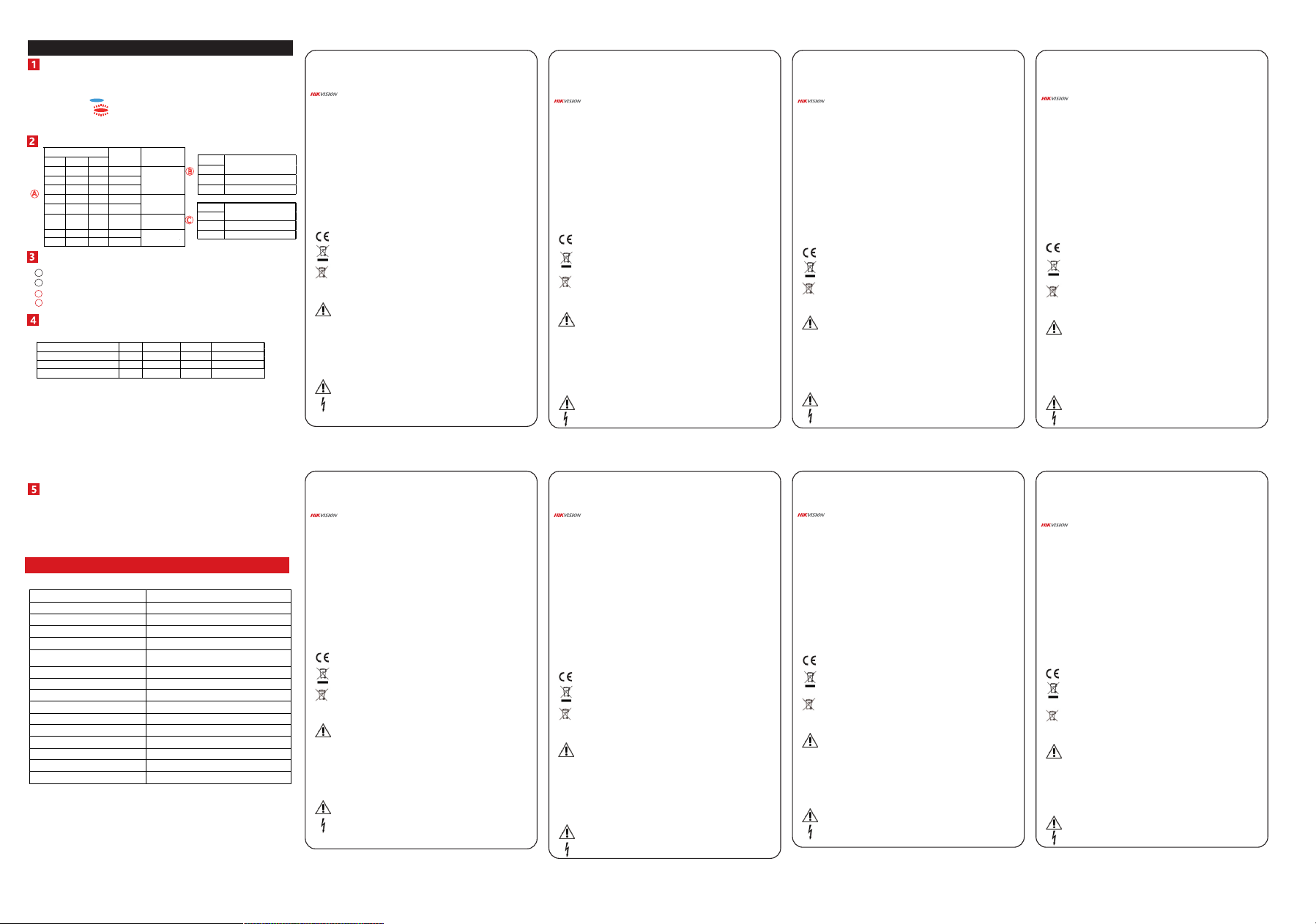
Appearance
1. Screw Cover 2. Screw 3. Terminal 4. Resistor Jumper
5. DIP Switch 6. LED Indicator
Noise Intensity:
DIP Settings
Specification
Installation
Resistor Wiring
Connection Type
Method 1: Use the jumper to select EOL (End of Line) resistance on
FAULT/TAMPER/ALARM pins.
Method 2: Add the resistor to FAULT/TAMPER/ALARM wiring ports.
Note: If EOL wiring is not used, leave the jumpers OFF. Do not force the
jumper if it is not matched the pin. Method 1 & 2 should not be used on the
ALARM/TAMPER at the same time.
a. Alarm Resistance: 1K, 2K2, 4K7, 5K6, 6K8
b. Tamper Resistance: 1K, 2K2, 4K7, 5K6
c. Fault Resistance: 1K, 2K2, 5K6
Note: The resistor must be connected in series with one end of the detector.
a. Normally Closed
b. Single End of Line Wiring
c. Double End of Line Wiring
d. Triple End of Line Wiring
Relay Status
Open Wiring Mounting
Concealed Wiring Mounting
Mounting with Rear Panel.
Mounting with Weld Plate .
I
II
a
b
A
B
C
Detection Range
Sensitivity
Digital Processing
Tamper Protection
Alarm Output
LED Indicator
Power Supply
Typical Voltage
Power Consumption
Operation Temperature
Storage Temperature
Operation Humidity
Dimension(W x H x D)
Shell material
Application Scenario
Weight
DIP Bit
1
ON
ON
ON
ON
OFF
OFF
OFF
OFF
3
ON
OFF
ON
OFF
ON
OFF
ON
OFF
2
ON
ON
OFF
OFF
ON
ON
OFF
OFF
Highest
Higher
High
Medium
Low
Lower
Lowest
Sensitivity
Level
Default
Set Scene
Concrete Wall
Steel Plate
Concrete Plate
ATM
Safe Box
ATM / Safe Box
Plank
Plank
Window
Frame
DIP Bit
4
ON
Enable
OFF
Disable
Enable/Disable
Displacement Alarm
DIP Bit
5
ON
High Noise
OFF
Low Noise
High Noise Adaption
Normal Alarm Fault Tamper
Alarm Relay Close Open Close Close
Fault Relay Close Close Open Close
Tamper Relay
Close Close Close Open
9 to 16 VDC
12 VDC
Max. 17 mA
-40 °C to 70 °C
-50 °C to 70 °C
10% to 90%
60 mm x 80 mm x 19.5 mm
Die-cast metal
Indoor
226 g
Up to 5 m Radius
8 Levels by DIP Switch
Support
Front and Rear
Normally Closed
Blue(Alarm), Red(Noise Indication)
Please use the power adapter complianting with LPS. The recommended power
adapter is made by Shenzhen Honor Electronic Co., Ltd.
UD23772B-B
7.Bouton antisabotage
Alarme : Bleu fixe pendant 3 s
Clignotement en rouge
Français
Apparence
1.Cache-vis 2.Vis 3.Borne 4.Cavalier de résistance
5.Commutateur DIP 6.Voyant lumineux
Intensité sonore :
Réglages des microcommutateurs
Spécification
Installation
Câblage des résistances
Type de connexion
Méthode 1 : utilisez le cavalier pour sélectionner la résistance d’extrémité de
ligne (EOL) sur les broches PANNE/ANTISABOTAGE/ALARME.
Méthode 2 : ajoutez la résistance aux ports de câblage
PANNE/ANTISABOTAGE/ALARME.
Remarque : si vous n’utilisez pas de câblage EOL, les cavaliers doivent rester
désactivés. Ne forcez pas sur le cavalier s’il n’est pas adapté à la broche. Les
méthodes 1 et 2 ne doivent pas être utilisées en même temps sur
l’ALARME/ANTI-SABOTAGE.
a. Résistance d’alarme : 1K, 2K2, 4K7, 5K6, 6K8
b. Résistance anti-sabotage : 1K, 2K2, 4K7, 5K6
c. Résistance aux pannes : 1K, 2K2, 5K6
Remarque : la résistance doit être connectée en série à une des extrémités du
détecteur.
a. Normalement fermé
b. Câblage d’une seule extrémité de ligne
c. Câblage d’une double extrémité de ligne
d. Câblage d’une triple extrémité de ligne
État du relais
Montage de câblage ouvert
Montage de câblage dissimulé
Montage avec panneau arrière.
Montage avec plaque de soudure.
I
II
a
b
A
B
C
Portée de la détection
Sensibilité
Traitement numérique
Protection antisabotage
Sortie d’alarme
Voyant lumineux
Alimentation électrique
Tension typique
Consommation d’énergie
Température de fonctionnement
Température de stockage
Humidité de fonctionnement
Dimensions (L x H x P)
Matériau du boîtier
Scénario d’application
Poids
Bit de DIP
1
MARCHE
MARCHE
MARCHE
MARCHE
ARRÊT
ARRÊT
ARRÊT
ARRÊT
3
MARCHE
ARRÊT
MARCHE
ARRÊT
MARCHE
ARRÊT
MARCHE
ARRÊT
2
MARCHE
MARCHE
ARRÊT
ARRÊT
MARCHE
MARCHE
ARRÊT
ARRÊT
Optimale
Plus
Haute
Moyenne
Basse
Abaisser
Minimum
Niveau de
sensibilité
Par défaut
Créer une scène
Mur en béton
Plaque en acier
Plaque en béton
DAB
Coffre-fort
DAB/coffre-fort
Planche
Planche
Cadre de
fenêtre
Bit de DIP
4
MARCHE
Activer
ARRÊT
Désactiver
Activer/désactiver l’alarme
de déplacement
Bit de DIP
5
MARCHE
Bruit fort
ARRÊT
Faible bruit
Adaptation aux
environnements bruyants
Normale Alarme Panne Anti-sabotage
Relais d’alarme Fermer Ouvert Fermer Fermer
Relais de défaut Fermer Fermer Ouvert Fermer
Relais antisabotage
Fermer Fermer Fermer Ouvert
9 à 16 V CC
12 V CC
17 mA max.
-40 °C à 70 °C
-50 °C à 70 °C
10 à 90 %
60 mm x 80 mm x 19,5 mm
Métal moulé sous pression
À l’intérieur
226 g
Rayon atteignant jusqu’à 5 m
8 niveaux par commutateur DIP
Pris en charge
Avant et arrière
Normalement fermé
Bleu (alarme), rouge (indication de bruit)
Veuillez uĘliser l’adaptateur secteur conforme à la norme LPS. L’adaptateur
secteur recommandé est fabriqué par Shenzhen Honor Electronic Co., Ltd.
7.Sabotagetaste
Alarm: 3 Sek. blaues Leuchten
Blinkt rot
Deutsch
Aufbau
1.Schraubenabdeckung 2.Schraube 3.Anschluss 4.Widerstandsbrücke
5.DIP-Schalter 6.LED-Anzeige
Geräuschintensität:
DIP-Schalter
Technische Daten
Installation
Widerstandsverdrahtung
Anschlussart
Methode 1: Verwenden Sie die Steckbrücke, um Leitungsabschluss-Widerstand
(EOL) an FEHLER/SABOTAGE/ALARM-Kontaktstiften zu wählen.
Methode 2: Schließen Sie den Widerstand an den
FEHLER/SABOTAGE/ALARM-Verdrahtungsanschlüssen an.
Hinweis: Verwenden Sie KEINE Steckbrücken, wenn EOL-Verdrahtung nicht
genutzt wird. Die Steckbrücke darf nicht gewaltsam aufgesteckt werden, wenn
sie nicht auf den Kontaktstift passt. Methode 1 und 2 dürfen nicht gleichzeitig
auf den ALARM/SABOTAGE-Stiftleisten verwendet werden.
a. Alarmwiderstand: 1K, 2K2, 4K7, 5K6, 6K8
b. Sabotage-Widerstand: 1K, 2K2, 4K7, 5K6
c. Fehlerwiderstand: 1K, 2K2, 5K6
Hinweis: Der Widerstand muss mit einem Kontakt des Melders in Reihe
geschaltet werden.
a. Normal geschlossen
b. Einzel-Leitungsabschlussverdrahtung
c. Doppel-Leitungsabschlussverdrahtung
d. Dreifach-Leitungsabschlussverdrahtung
Relaisstatus
Montage mit offener Verdrahtung
Montage mit verdeckter Verdrahtung
Montage mit Rückwand.
Montage mit Schweißplatte.
I
II
a
b
A
B
C
Erkennungsbereich
Empfindlichkeit
Digitale Verarbeitung
Sabotageschutz
Alarmausgang
LED-Anzeige
Spannungsversorgung
Typische Spannung
Stromverbrauch
Betriebstemperatur
Lagertemperatur
Betriebsfeuchtigkeit
Abmessungen (B x H x T)
Gehäusematerial
Anwendungsszenario
Gewicht
DIP-Bit
1
EIN
EIN
EIN
EIN
AUS
AUS
AUS
AUS
3
EIN
AUS
EIN
AUS
EIN
AUS
EIN
AUS
2
EIN
EIN
AUS
AUS
EIN
EIN
AUS
AUS
Höchste
Höher
Hoch
Mittel
Niedrig
Niedriger
Niedrigste
Empfindlichk
eitsstufe
Standard
Szene einstellen
Betonwand
Stahlplatte
Betonplatte
ATM
Safe
ATM / Safe
Bohle
Bohle
Fensterrahmen
DIP-Bit
4
EIN
Aktivieren
AUS
Deaktivieren
Verdrängungsalarm
aktivieren/deaktivieren
DIP-Bit
5
EIN
Starkes Geräusch
AUS
Geringes Geräusch
Hohe Geräuschanpassung
Normal Alarm Fehler Sabotage
Alarmrelais Schließen Öffnen Schließen Schließen
Fehlerrelais Schließen Schließen Öffnen Schließen
Sabotagerelais
Schließen Schließen Schließen Öffnen
9 bis 16 V Gleichspannung
12 V DC
Max. 17 mA
-40 °C bis 70 °C
-50 °C bis 70 °C
10 % bis 90 %
60 mm x 80 mm x 19,5 mm
Metall-Druckguss
Innen
226 g
Bis zu 5 m Radius
8 Stufen über DIP-Schalter
Unterstützt
Vorne und hinten
Normal geschlossen
Blau (Alarm), Rot (Geräuschanzeige)
BiŔe verwenden Sie ein LPS-konformes Netzteil (mit begrenzter Leistung). Das
empfohlene Netzteil wird von Shenzhen Honor Electronic Co., Ltd. hergestellt.
7.Botón antimanipulación
Alarma: Azul fijo durante 3 s
Parpadeo rojo
Español
Apariencia
1.Tapa del tornillo 2.Tornillo 3.Terminal
4.Interruptor Jumper del resistor 5.Interruptor DIP 6.Piloto led
Intensidad de ruido:
Ajustes de los conmutadores DIP
Especificación
Instalación
Cableado de la resistencia
Tipo de conexión
Método 1: Use el Jumper para seleccionar la resistencia EOL (fin de línea) en
los pasadores marcados FAULT/TAMPER/ALARM.
Método 2: Añada la resistencia a los puertos de cableado de
FAULT/TAMPER/ALARM.
Nota: Si no usa un cableado de fin de línea (EOL), deje los puentes
desconectados. No fuerce las resistencias si no coinciden con los pines. No
utilice el método 1 ni el método 2 con respecto a ALARMA/MANIPULACIÓN al
mismo tiempo.
a. Resistencia de alarma: 1K, 2K2, 4K7, 5K6, 6K8
b. Resistencia a manipulación: 1K, 2K2, 4K7, 5K6
c. Resistencia para el circuito de Fallos (FAULT): 1K, 2K2, 5K6
Nota: La resistencia se debe conectar en serie con uno de los extremos del
detector.
a. Normalmente cerrado
b. Cableado de Fin de línea único
c. Cableado de Fin de línea doble
d. Cableado de Fin de línea triple
Estado del relé
Montaje de cableado abierto
Montaje de cableado oculto
Montaje con panel trasero.
Montaje con placa soldada.
I
II
a
b
A
B
C
Alcance de detección
Sensibilidad
Procesamiento digital
Protección antimanipulación
Salida de alarma
Piloto led
Fuente de alimentación
Tensión normal
Consumo de energía
Temperatura de funcionamiento
Temperatura de almacenamiento
Humedad de funcionamiento
Dimensiones
Material de la carcasa
Escenarios de aplicación
Peso
Bit delDIP
1
ACTIVADO
ACTIVADO
ACTIVADO
ACTIVADO
DESACTIV
ADO
DESACTI
VADO
DESACTIV
ADO
DESACTIV
ADO
3
ACTIVADO
DESACTIV
ADO
ACTIVADO
DESACTIV
ADO
ACTIVADO
DESACTIV
ADO
ACTIVADO
DESACTIV
ADO
2
ACTIVADO
ACTIVADO
DESACTIV
ADO
DESACTIV
ADO
ACTIVADO
ACTIVADO
DESACTIV
ADO
DESACTIV
ADO
Más alta
Más alto
Alta
Media
Baja
Más bajo
La másbaja
Nivel de
sensibilidad
Predeterminado
Establecer escena
Pared dehormigón
Placa deacero
Placa decemento
Cajero
Caja deseguridad
Cajero /Caja de
seguridad
Tablón
Tablón
Marco de ventana
Bit delDIP
4
ACTIVADO
Habilitar
DESACTIVADO
Inhabilitar
Habilitar/Inhabilitar laalarma
de desplazamiento
Bit delDIP
5
ACTIVADO
Ruido fuerte
DESACTIVADO
Poco ruido
Adaptación aruidos fuertes
Normal Alarma Fallo Sabotaje
Relé de alarma Cerrar Abierto Cerrar Cerrar
Relé de fallo Cerrar Cerrar Abierto Cerrar
Retardo de manipulación
Cerrar Cerrar Cerrar Abierto
De 9 a 16 V CC
12 VCC
17 mA máx.
de -40 °C a 70 °C
de -50 °C a 70 °C
10 % a 90 %
60 mm x 80 mm x 19,5 mm
Metal fundido
En interiores
226 g
Hasta 5 m de radio
8 niveles de ajuste por interruptor DIP
Soporte
Parte delantera y trasera
Normalmente cerrado
Azul (Alarma), Rojo (Indicación de ruido)
Use un adaptador de corriente que cumpla con la normaĘva de Fuentes de
Alimentación de Baja Potencia. El adaptador eléctrico recomendado es el
fabricado por Shenzhen Honor Electronic Co., Ltd.
7.Pulsante manomissione
Allarme: Blu fisso per 3 secondi
Rosso lampeggiante
Italiano
Aspetto
1.Coperchio a vite 2.Vite 3.Terminale 4.Ponticello resistore
5.Microinterruttore 6.Indicatore LED
Intensità rumore:
Impostazioni microinterruttore
Specifiche
Installazione
Cablaggio della resistenza
Tipo di collegamento
Metodo 1: utilizzare il ponticello per selezionare la resistenza di fine linea
(EOL) sui perni GUASTO/MANOMISSIONE/ALLARME.
Metodo 2: aggiungere la resistenza alle porte di cablaggio
GUASTO/MANOMISSIONE/ALLARME.
Nota: se non si utilizza il cablaggio EOL, lasciare i ponticelli DISINSERITI. Non
forzare i ponticelli se non si trovano in corrispondenza dei perni. Il primo e il
secondo metodo non devono essere utilizzati contemporaneamente.
a. Resistenza allarme: 1K, 2K2, 4K7, 5K6, 6K8
b. Resistenza antimanomissione: 1K, 2K2, 4K7, 5K6
c. Resistenza Guasto: 1K, 2K2, 5K6
Nota: Il resistore deve essere collegato in serie con un terminale del rilevatore.
a. Normalmente chiuso
b. Cablaggio di fine linea singolo
c. Cablaggio di fine linea doppio
d. Cablaggio di fine linea triplo
Stato relè
Montaggio cablaggio aperto
Montaggio cablaggio nascosto
Montaggio con pannello posteriore.
Montaggio con piastra di saldatura.
I
II
a
b
A
B
C
Campo di rilevamento
Sensibilità
Elaborazione digitale
Protezione antimanomissione
Uscita allarme
Indicatore LED
Alimentazione
Tensione tipica
Assorbimento
Temperatura operativa
Temperatura di stoccaggio
Umidità operativa
Dimensioni (L x A x P)
Materiale del guscio
Scenario dell'applicazione
Peso
Bit DIP
1
ATTIVO
ATTIVO
ATTIVO
ATTIVO
DISATTIVO
DISATTIVO
DISATTIVO
DISATTIVO
3
ATTIVO
DISATTIVO
ATTIVO
DISATTIVO
ATTIVO
DISATTIVO
ATTIVO
DISATTIVO
2
ATTIVO
ATTIVO
DISATTIVO
DISATTIVO
ATTIVO
ATTIVO
DISATTIVO
DISATTIVO
Massimo
Superiore
Alto
Materiale
Basso
Inferiore
Minimo
Livello di
sensibilità
Default
Impostazione
scenario
Parete dicemento
Piastra diacciaio
Piastra dicemento
ATM
Safe Box
ATM /Safe Box
Tavola
Tavola
Telaio finestra
Bit DIP
4
ATTIVO
Abilita
DISATTIVO
Disabilita
Abilitazione/Disabilitazione
allarme dispostamento
Bit DIP
5
ATTIVO
Rumore elevato
DISATTIVO
Rumore basso
Adattamento arumore elevato
Normale Allarme Errore Manomissione
Relè di allarme Chiudi Aperto Chiudi Chiudi
Relè guasto Chiudi Chiudi Aperto Chiudi
Relè manomissione
Chiudi Chiudi Chiudi Aperto
9-16 V CC
12 V CC
Max. 17 mA
Da -40 °C a 70 °C
Da -50 °C a 70 °C
Da 10% a 90%
60 mm x 80 mm x 19,5 mm
Metallo pressofuso
Interno
226 g
Raggio fino a 5 m
8 livelli da microinterruttore
Supporto
Anteriore e posteriore
Normalmente chiuso
Blu (allarme), Rosso (indicazione di rumore)
UĘlizzare l'adaŔatore di alimentazione conforme a LPS. L'adaŔatore di
alimentazione consigliato è prodoŔo da Shenzhen Honor Electronic Co., Ltd.
7.Botão de violação
Alarme: Azul fixo por 3 s
Vermelho piscando
Português
Apresentação
1.Tampa de parafuso 2.Parafuso 3.Terminal 4.Jumper do resistor
5.Chaves DIP 6.Indicador LED
Intensidade do ruído:
Configurações de DIP
Especificações
Instalação
Conexão do resistor
Tipo de conexão
Método 1: use o jumper para selecionar a resistência EOL (fim de linha) nos
pinos FALHA/VIOLAÇÃO/ALARME.
Método 2: adicione o resistor às portas de fiação FALHA/VIOLAÇÃO/ALARME.
Observação: se a fiação EOL não for usada, deixe os jumpers desligados. Não
force o jumper se ele não corresponder ao pino. Os métodos 1 e 2 não devem
ser usados em ALARME/VIOLAÇÃO ao mesmo tempo.
a. Resistência do alarme: 1K, 2K2, 4K7, 5K6, 6K8
b. Resistência de antiviolação: 1K, 2K2, 4K7, 5K6
c. Resistência a falhas: 1K, 2K2, 5K6
Observação: o resistor deve ser conectado em série com uma extremidade do
detector.
a. Normalmente fechado
b. Fiação de fim de linha único
c. Fiação de fim de linha duplo
d. Fiação de fim de linha triplo
Status do relé
Montagem com fiação aberta
Montagem com fiação oculta
Montagem com painel traseiro.
Montagem com placa de solda.
I
II
a
b
A
B
C
Faixa de detecção
Sensibilidade
Processamento digital
Proteção antiviolação
Saída de alarme
Indicador LED
Fonte de alimentação
Tensão típica
Consumo de energia
Temperatura de operação
Temperatura de armazenamento
Umidade de operação
Dimensões (L x A x P)
Material do invólucro
Cenário de aplicação
Peso
Bit DIP
1
LIGADO
LIGADO
LIGADO
LIGADO
DESLIGADO
DESLIGADO
DESLIGADO
DESLIGADO DESLIGADO
3
LIGADO
DESLIGADO
LIGADO
DESLIGADO
LIGADO
DESLIGADO
LIGADO
DESLIGADO
2
LIGADO
LIGADO
DESLIGADO
DESLIGADO
LIGADO
LIGADO
DESLIGADO
Altíssimo
Mais alto
Alto
Médio
Baixo
Mais baixo
Baixíssimo
Nível de
sensibilidade
Padrão
Local
Parede deconcreto
Placa deaço
Placa deconcreto
Caixa eletrônico
Cofre
Caixa
eletrônico/cofre
Prancha
Prancha
Armação da
janela
Bit DIP
4
LIGADO
Ativar
DESLIGADO
Desativar
Habilitar/desabilitar alarmede
deslocamento
Bit DIP
5
LIGADO
Alto ruído
DESLIGADO
Baixo ruído
Adaptação dealto ruído
Normal Alarme Falha Violação
Relé de alarme Fechar Abrir Fechar Fechar
Relé de falha Fechar Fechar Abrir Fechar
Relé de violação
Fechar Fechar Fechar Abrir
9 a 16 VCC
12 VCC
Máx. de 17 mA
-40 °C a 70 °C
-50 °C a 70 °C
10% a 90%
60 mm x 80 mm x 19,5 mm
Metal fundido
Interior
226 g
Raio de até 5 m
8 níveis por chave DIP
Suporte
Frontal e traseira
Normalmente fechado
Azul (alarme), vermelho (indicação de ruído)
Use o adaptador de energia compaUvel com LPS. O adaptador de energia
recomendado é fabricado pela Shenzhen Honor Electronic Co., Ltd.
7.Кнопка взлома
Тревога: Постоянный синий в течение 3 с
Мигает красным цветом
Русский
Внешний вид
1.Крышка на винте 2.Винт 3.Клеммная колодка 4.Резистивная перемычка
5.DIP-переключатель 6.Светодиодный индикатор
Интенсивность шума:
Настройки DIP
Технические данные
Установка
Разводка для подключения резистора
Тип соединения
Метод 1: Используйте перемычку для выбора концевого резистора на
контактах НЕИСПРАВНОСТЬ/ЗАЩИТА ОТ ВЗЛОМА/СИГНАЛИЗАЦИЯ.
Метод 2: Установите резистор на порты подключения
НЕИСПРАВНОСТЬ/ЗАЩИТА ОТ ВЗЛОМА/СИГНАЛИЗАЦИЯ.
Примечание. Если резистор в конце линии не используется, отставьте
перемычки в положении ВЫКЛ. Не прилагайте чрезмерного усилия к
перемычке, если она не подходит к контакту. Способы 1 и 2 не должны
применяться в группе "СИГНАЛИЗАЦИЯ/ЗАЩИТА ОТ ВЗЛОМА"
одновременно.
a. Стойкость сигнализации: 1 кОм, 2,2 кОм, 4,7 кОм, 5,6 кОм, 6,8 кОм
b. Стойкость к взлому: 1 кОм, 2,2 кОм, 4,7 кОм, 5,6 кОм
c. Сопротивление в месте КЗ: 1K, 2K2, 5K6
Примечание. Резистор подключается последовательно с датчиком.
a. Нормально замкнутый
b. Линия с одним концевым резистором
b. Линия с двумя концевыми резисторами
d. Линия с тремя концевыми резисторами
Состояние реле
Монтаж с открытой проводкой
Монтаж со скрытой проводкой
Монтаж через заднюю панель.
Монтаж на приварной пластине.
I
II
a
b
A
B
C
Диапазон обнаружения
Чувствительность
Цифровая обработка
Защита от взлома
Тревожный выход
Светодиодный индикатор
Электропитание
Номинальное напряжение
Потребляемая мощность
Рабочая температура
Температура при хранении
Влажность в рабочем режиме
Размеры (Ш x В x Г)
Материал корпуса
Вариант применения
Вес
Поз. DIP
1
ВКЛ.
ВКЛ.
ВКЛ.
ВКЛ.
ВЫКЛ.
ВЫКЛ.
ВЫКЛ.
ВЫКЛ.
3
ВКЛ.
ВЫКЛ.
ВКЛ.
ВЫКЛ.
ВКЛ.
ВЫКЛ.
ВКЛ.
ВЫКЛ.
2
ВКЛ.
ВКЛ.
ВЫКЛ.
ВЫКЛ.
ВКЛ.
ВКЛ.
ВЫКЛ.
ВЫКЛ.
Максимальная
Более высокий
Высокий
Материал
Низкий
Низкий
Минимальный
Уровень
чувствитель
ности
По умолчанию
Сцена
Бетонная стена
Стальная
пластина
Бетонная плита
ATM
Сейф
ATM / сейф
Дощатая
Дощатая
Рама окна
Поз. DIP
4
ВКЛ.
Включено
ВЫКЛ.
Отключено
Включение/отключение
сигнализации о
перемещении
Поз. DIP
5
ВКЛ.
Высокий шум
ВЫКЛ.
Низкий шум
Адаптация к высокому шуму
Нормальный Тревога Неисправность Взлом
Реле сигнала тревоги Замкнуто Открыто Замкнуто Замкнуто
Реле неисправности Замкнуто Замкнуто Открыто Замкнуто
Реле взлома
Замкнуто Замкнуто Замкнуто Открыто
От 9 до 16 В пост. тока
12 В пост. тока
Макс. 17 мА
От -40 °C до 70 °C
От -50 °C до 70 °C
10–90%
60 x 80 x 19,5 мм
Металлическая отливка
Внутри помещения
226 г
Радиус до 5 м
8 уровней, устанавливаемых
DIP-переключателем
Поддержка
Передний и задний
Нормально замкнутый
Синий (сигнализация), красный
(индикация шума)
Используйте адаптер питания, соответствующий LPS. Рекомендуется
адаптер питания производства компании Shenzhen Honor Electronic Co., Ltd.
7.Sabotageknop
Alarm: Brand 3 sec. blauw
Knippert rood
Nederlands
Verschijning
1.Schroefdopje 2.Schroef 3.Terminal 4.Weerstandsjumper
5.DIP-schakelaar 6.Led-indicator
Geluidsintensiteit:
DIP-instellingen
Specificatie
Installatie
Bedrading van weerstand
Verbindingstype
Methode 1: Gebruik de jumper om EOL-weerstand (End of Line) te selecteren
op STORING-/SABOTAGEALARM-pinnen.
Methode 2: Voeg de weerstand toe aan
STORING-/SABOTAGEALARM-bedradingspoorten.
Opmerking: Als EOL-bedrading niet wordt gebruikt, laat u de jumpers uit.
Forceer de jumper niet als deze niet overeenkomt met de pin. Methode 1 &
2 mogen niet worden gebruikt op het ALARM/SABOTAGE tegelijkertijd.
a. Alarmweerstand: 1K, 2K2, 4K7, 5K6, 6K8
b. Sabotageweerstand: 1K, 2K2, 4K7, 5K6
c. Storingsweerstand: 1K, 2K2, 5K6
Opmerking: De weerstand moet verbonden zijn in series met een eind van de
detector.
a. Normaal gesloten
b. Enkele End of Line-bedrading
c. Dubbele End of Line-bedrading
d. Drievoudige End of Line-bedrading
Relaisstatus
Open bedradingsmontage
Verborgen bedradingsmontage
Montage met achterpaneel.
Montage met lasplaat.
I
II
a
b
A
B
C
Detectiebereik
Gevoeligheid
Digitale verwerking
Sabotagebescherming
Alarm-uitgang
Led-indicator
Stroomvoorziening
Typische spanning
Stroomverbruik
Bedrijfstemperatuur
Opslagtemperatuur
Luchtvochtigheid tijdens bedrijf
Afmetingen (B x H x D)
Materiaal behuizing
Toepassingsscenario
Gewicht
DIP-bit
1
AAN
AAN
AAN
AAN
UIT
UIT
UIT
UIT
3
AAN
UIT
AAN
UIT
AAN
UIT
AAN
UIT
2
AAN
AAN
UIT
UIT
AAN
AAN
UIT
UIT
Hoogste
Hoger
Hoog
Midden
Laag
Lager
Laagste
Gevoeligheid
sniveau
Standaard
Scène instellen
Betonnen muur
Stalen plaat
Betonnen plaat
Pinautomaat
Kluis
Pinautomaat/kluis
Plank
Plank
Raamkozijn
DIP-bit
4
AAN
Inschakelen
UIT
Uitschakelen
Verplaatsingsalarm
in-/uitschakelen
DIP-bit
5
AAN
Hoog geluid
UIT
Laag geluid
Hoge geluidsaanpassing
Normaal Alarm Storing Saboteren
Alarmrelais Sluiten Openen Sluiten Sluiten
Storingsrelais Sluiten Sluiten Openen Sluiten
Sabotagerelais
Sluiten Sluiten Sluiten Openen
9 tot 16 VDC
12 V DC
Max. 17 mA
-40 °C tot 70 °C
-50 °C tot 70 °C
10% tot 90%
60 mm x 80 mm x 19,5 mm
Gegoten metaal
Binnenshuis
226 g
Tot een straal van 5 m
8 niveaus via DIP-schakelaar
Ondersteuning
Voor en achter
Normaal gesloten
Blauw (alarm), rood (geluidsindicatie)
Gebruik een voedingsadapter die compaĘbel is met LPS. De aanbevolen
voedingsadapter wordt vervaardigd door Shenzhen Honor Electronic Co., Ltd.
7.Kurcalama Düğmesi
Alarm: 3 sn. Kesintisiz Mavi
Yanıp Sönen Kırmızı
Türkçe
Görünüm
1.Vidalı Kapak 2.Vidalı 3.Terminal 4.Direnç Atlama Teli
5.DIP Anahtarı 6.LED Göstergesi
Gürültü Yoğunluğu:
DIP Ayarları
Özellikler
Kurulum
Rezistans Kabloları
Bağlantı Tipi
Yöntem 1: ARIZA/KURCALAMA/ALARM pinlerinde EOL (Hat Sonu) direncini
seçmek için atlama telini kullanın.
Yöntem 2: Direnci ARIZA/KURCALAMA/ALARM kablolama bağlantı noktalarına
ekleyin.
Not: EOL kabloları kullanılmıyorsa, atlama tellerini KAPALI bırakın. Pime
uymuyorsa atlama telini zorlamayın. Yöntem 1 ve 2, ALARM/KURCALAMA
üzerinde aynı anda kullanılmamalıdır.
a. Alarm Direnci: 1K, 2K2, 4K7, 5K6, 6K8
b. Kurcalama Direnci: 1K, 2K2, 4K7, 5K6
c. Arıza Direnci: 1K, 2K2, 5K6
Not: Direnç, dedektörün bir ucu ile seri bağlanmalıdır.
a. Normalde Kapalı
b. Tek Hat Sonu Kablolaması
c. Çi� Hat Sonu Kablolaması
d. Üçlü Hat Sonu Kablolaması
Röle Durumu
Açık Kablo Montajı
Gizli Kablo Montajı
Arka Panel ile Montaj.
Kaynak Plakası ile Montaj.
I
II
a
b
A
B
C
Algılama aralığı
Hassasiyet
Dijital İşleme
Kurcalama Koruması
Alarm Çıkışı
LED Göstergesi
Güç Kaynağı
Tipik Voltaj
Güç Tüketimi
Çalışma Sıcaklığı
Depolama sıcaklığı
Çalışma Nemi
Boyut (G x Y x D)
Gövde malzemesi
Uygulama Senaryosu
Ağırlık
DIP Bit
1
AÇIK
AÇIK
AÇIK
AÇIK
KAPALI
KAPALI
KAPALI
KAPALI
3
AÇIK
KAPALI
AÇIK
KAPALI
AÇIK
KAPALI
AÇIK
KAPALI
2
AÇIK
AÇIK
KAPALI
KAPALI
AÇIK
AÇIK
KAPALI
KAPALI
En Yüksek
Daha Yüksek
Yüksek
Orta
Düşük
Daha Düşük
En Düşük
Hassasiyet
Düzeyi
Varsayılan
SahneyiAyarla
Beton Duvar
Çelik Levha
Beton Levha
ATM
Kasa
ATM / Kasa
Payanda
Payanda
Pencere
Çerçevesi
DIP Bit
4
AÇIK
Etkinleştir
KAPALI
Devre Dışı Bırak
Yer Değiştirme Alarmını
Etkinleştir/Devre Dışı Bırak
DIP Bit
5
AÇIK
Yüksek Gürültü
KAPALI
Düşük Gürültü
Yüksek Gürültü Uyarlaması
Normal Alarm Arıza Kurcalama
Alarm Rölesi Kapat Aç Kapat Kapat
Arıza Rölesi Kapat Kapat Aç Kapat
Kurcalama Rölesi
Kapat Kapat Kapat Aç
9 ila 16 VDC
12 VDC
Maks. 17mA
-40 °C ila 70 °C
-50 °C ila 70 °C
%10 ila %90
60 mm x 80 mm x 19,5 mm
Döküm metal
İç mekan
226g
5 m'ye kadar Yarıçap
DIP Switch ile 8 Seviye
Destek
Ön ve Arka
Normalde Kapalı
Mavi (Alarm), Kırmızı (Gürültü Göstergesi)
Lü�en LPS ile uyumlu güç adaptörünü kullanın. Önerilen güç adaptörü Shenzhen
Honor Electronic Co., Ltd. tara�ndan yapılmış�r.
7.Manipulationsknap
Alarm: Konstant blåt i 3s
Blinker rødt
Dansk
Udseende
1.Skruedæksel 2.Skrue 3.Terminal 4.Jumper modstand
5.DIP-kontakt 6.LED-kontrollampe
Støjintensitet:
DIP-indstilling
Specifikation
Installation
Kabelføring af modstand
Forbindelsestype
Metode 1: Brug jumperen til at vælge modstand ved slutning af linje (EOL) på
benene FEJL/MANIPULATION/ALARM.
Metode 2: Føj modstanden til kabelportene FEJL/MANIPULATION/ALARM.
Bemærk: Hvis EOL-kabelføring ikke anvendes, skal jumperne IKKE sættes på.
Tving ikke jumperen, hvis den ikke passer med benet. Metode 1 og 2 bør ikke
anvendes på ALARM/MANIPULATION samtidig.
a. Alarmmodstand: 1K, 2K2, 4K7, 5K6, 6K8
b. Manipulationsmodstand: 1K, 2K2, 4K7, 5K6
c. Fejlmodstand: 1K, 2K2, 5K6
Bemærk: Modstanden skal serieforbindes med detektorens ene ende.
a. Normalt lukket
b. Enkelt EOL-kabelføring
c. Dobbelt EOL-kabelføring
d. Tredobbelt EOL-kabelføring
Relæstatus
Montering med synlige kabler
Montering med skjulte kabler
Montering med bagpanel.
Montering med svejseplade.
I
II
a
b
A
B
C
Detektionsrækkevidde
Følsomhed
Digital behandling
Manipulationsbeskyttelse
Alarmudgang
LED-kontrollampe
Strømforsyning
Typisk spænding
Effektforbrug
Driftstemperatur
Opbevaringstemperatur
Fugtighed ved drift
Mål (B x H x D)
Kabinetmateriale
Anvendelsessted
Vægt
DIP-bit
1
TÆNDT
TÆNDT
TÆNDT
TÆNDT
SLUKKET
SLUKKET
SLUKKET
SLUKKET
3
TÆNDT
SLUKKET
TÆNDT
SLUKKET
TÆNDT
SLUKKET
TÆNDT
SLUKKET
2
TÆNDT
TÆNDT
SLUKKET
SLUKKET
TÆNDT
TÆNDT
SLUKKET
SLUKKET
Højeste
Højere
Høj
Middel
Lav
Lavere
Laveste
Følsomhedsn
iveau
Standard
Angiv scenarie
Betonvæg
Stålplade
Betonplade
ATM
Sikkerhedsboks
ATM /
Sikkerhedsboks
Planke
Planke
Vinduesramme
DIP-bit
4
TÆNDT
Aktivér
SLUKKET
Deaktivér
Aktivér/Deaktivér
forskydningsalarm
DIP-bit
5
TÆNDT
Kraftig støj
SLUKKET
Lav støj
Tilpasning for kraftigstøj
Normal Alarm Fejl Manipulation
Alarmrelæ Luk Åbn Luk Luk
Fejlrelæ Luk Luk Åbn Luk
Manipulationsrelæ
Luk Luk Luk Åbn
9-16 V jævnstrøm
12 V jævnstrøm
Maks. 17 mA
-40 °C til 70 °C
-50 °C til 70 °C
10-90 %
60 mm x 80 mm x 19,5 mm
Støbt metal
Indendørs
226 g
Op til 5 m radius
8 niveauer via DIP-kontakt
Support
Front og bagside
Normalt lukket
Blå(Alarm), Rød(Støjindikation)
Brug den strømforsyning, der overholder LPS. Den anbefalede strømforsyning er
fremsĘllet af Shenzhen Honor Electronic Co., Ltd.
7.Szabotázs gomb
Riasztás: Folyamatosan kék 3 mp.-ig
Villogó vörös
Magyar
Külső megjelenés
1.Csavarvédő 2.Csavar 3.Érintkező 4.Ellenállás jumper
5.DIP kapcsoló 6.LED
Zaj erőssége:
DIP beállítások
Specifikáció
Telepítés
Ellenállás bekötése
Csatlakozás típusa
1. módszer: A jumperrel válassza ki az EOL (vonalvég) ellenállást a
FAULT/TAMPER/ALARM (HIBA/SZABOTÁZS/RIASZTÁS) lábakon.
2. módszer: Csatlakoztassa az ellenállást a HIBA/SZABOTÁZS/RIASZTÁS
huzalcsatlakozókra.
Megjegyzés: Ha nem az EOL bekötést használja, akkor a jumpereket hagyja KI
állásban. Ne erőltesse a jumpert, ha az nem illik a tűhöz. Az RIASZTÁS /
SZABOTÁZS érintkezőn az 1. és a 2. módszer nem használható egyszerre.
a. Riasztás-ellenállás: 1k, 2k2, 4k7, 5k6, 6k8
b. Szabotázs-ellenállás: 1k, 2k2, 4k7, 5k6
c. Hibajelző ellenállás: 1K, 2K2, 5K6
Megjegyzés: Az ellenállást sorosan kell csatlakoztatniaz érzékelő egyik végéhez.
a. Nyitóérintkező
b. Vonalhuzalozás egyszeres vége
c. Vonalhuzalozás dupla vége
d. Vonalhuzalozás tripla vége
Relé állapota
Beszerelés nyitott vezetékekkel
Beszerelés rejtett vezetékekkel
Beszerelés hátlappal.
Beszerelés hegesztett lappal.
I
II
a
b
A
B
C
Észlelési tartomány
Érzékenység
Digitális feldolgozás
Szabotázsvédelem
Riasztáskimenet
LED
Tápellátás
Jellemző feszültség
Teljesítményfelvétel
Üzemi hőmérséklet
Tárolási hőmérséklet
Üzemi páratartalom
Méretek (szél. x mag. x mély.)
Burkolat anyaga
Alkalmazási forgatókönyv
Súly
DIP Bit
1
BE
BE
BE
BE
KI
KI
KI
KI
3
BE
KI
BE
KI
BE
KI
BE
KI
2
BE
BE
KI
KI
BE
BE
KI
KI
Legmagasabb
Magasabb
Magas
Közepes
Alacsony
Alacsonyabb
Legalacsonyabb
Érzékenységi
szint
Alapértelmezett
Helyszín
beállítása
Beton fal
Acél lemez
Beton lemez
ATM
Biztonságidoboz
ATM / biztonsági
doboz
Palánk
Palánk
Ablak keret
DIP Bit
4
BE
Bekapcsolás
KI
Kikapcsolás
Elmozdulási riasztás
bekapcsolása/kikapcsolása
DIP Bit
5
BE
Magas zajszint
KI
Alacsony zajszint
Alkalmazkodás magas
zajszinthez
Normál Riasztó Hiba Szabotázs
Riasztórelé Zárás Nyitás Zárás Zárás
Hibajelző relé Zárás Zárás Nyitás Zárás
Szabotázsjelző relé
Zárás Zárás Zárás Nyitás
9 – 16 V DC
12 V DC
Max. 17 mA
-40 °C - 70 °C
-50 °C - 70 °C
10% – 90%
60 mm x 80 mm x 19,5 mm
Öntöttvas
Beltér
226g
Legfeljebb 5m hatósugár
8 szint a DIP kapcsolóval
Támogatás
Első és hátsó
Nyitóérintkező
Kék (riasztás), vörös (zajészlelés)
Kérjük, használjon az LPS előírásnak megfelelő adaptert. Javasolt a Shenzhen
Honor Electronic Co. Ltd. Által gyártoŔ adapter használata.
7.Przycisk zabezpieczenia antysabotażowego
Alarm: Włączony (niebieski) przez 3 s
Miga (czerwony)
Polski
Elementy urządzenia
1.Pokrywa śruby 2.Śruba 3.Złącze 4.Przełącznik rezystora
5.Przełącznik DIP 6.Wskaźnik
Głośność hałasu:
Ustawienia DIP
Specyfikacje
Instalacja
Podłączenie rezystora
Typ połączenia
Metoda 1: wybranie przełącznikiem rezystancji EOL (End of Line) dla końcówek
ALARM / SABOTAŻ / USTERKA.
Metoda 2: dodanie rezystora do końcówek ALARM / SABOTAŻ / USTERKA.
Uwaga: Jeżeli konfiguracja połączeń EOL nie jest używana, należy usunąć
zworki. Nie wolno dociskać zworki, jeżeli nie pasuje ona do końcówek. Nie
wolno używać metod 1 i 2 równocześnie do wykonania połączeń
ALARM/SABOTAŻ.
a. Rezystancja alarmu:1k, 2k2, 4k7, 5k6, 6k8
b. Rezystancja sabotażu:1k, 2k2, 4k7, 5k6
c. Rezystancja usterki:1k, 2k2, 5k6
Uwaga: Rezystor musi być podłączony szeregowo do jednego ze złączy
detektora.
a. Rozwierne
b. Połączenia SEOL
c. Połączenia DEOL
d. Połączenia TEOL
Stan przekaźnika
Montaż z połączeniem zewnętrznym
Montaż z połączeniem wewnętrznym
Montaż z panelem tylnym.
Montaż z podstawą.
I
II
a
b
A
B
C
Zasięg detekcji
Czułość
Przetwarzanie cyfrowe
Zabezpieczenie antysabotażowe
Wyjście alarmowe
Wskaźnik
Zasilanie
Typowe napięcie
Pobór mocy
Temperatura (użytkowanie)
Temperatura (przechowywanie)
Wilgotność (użytkowanie)
Wymiary (szer. x wys. x gł.)
Materiał obudowy
Zastosowanie
Waga
Poz. DIP
1
WŁ.
WŁ.
WŁ.
WŁ.
WYŁ.
WYŁ.
WYŁ.
WYŁ.
3
WŁ.
WYŁ.
WŁ.
WYŁ.
WŁ.
WYŁ.
WŁ.
WYŁ.
2
WŁ.
WŁ.
WYŁ.
WYŁ.
WŁ.
WŁ.
WYŁ.
WYŁ.
Najwyższa
Wyższa
Wysoka
Średnia
Niska
Niższa
Najniższa
Czułość
Domyślna
Lokalizacja
Mur betonowy
Panel stalowy
Panel betonowy
Bankomat
Sejf
Bankomat / sejf
Panel
Panel
Rama okna
Poz. DIP
4
WŁ.
Włącz
WYŁ.
Wyłączone
Włączenie/wyłączenie
alarmu przemieszczenia
Poz. DIP
5
WŁ.
Duża głośność
WYŁ.
Mała głośność
Warunki głośnego hałasu
Prawidłowe Alarm Usterka Sabotaż
Przekaźnik alarmowy Zamknięte Otwarte Zamknięte Zamknięte
Przekaźnik usterki Zamknięte Zamknięte Otwarte Zamknięte
Przekaźnik zabezpieczenia
antysabotażowego
Zamknięte Zamknięte Zamknięte Otwarte
9–16 V DC
12 V DC
Maks. 17 mA
Od –40°C do +70°C
Od –50°C do +70°C
Od 10% do 90%
60 mm x 80 mm x 19,5 mm
Odlew metalowy
W budynku
226 g
Promień maks. 5 m
8 ustawień przełącznika DIP
Obsługiwane
Panel przedni i tylny
Rozwierne
Niebieski (alarm), czerwony (detekcja hałasu)
Używaj zasilacza spełniającego wymagania dotyczące źródeł zasilania z własnym
ograniczeniem (LPS). Zalecany zasilacz jest produkowany przez firmę Shenzhen
Honor Electronic Co., Ltd.
7.Tlačítko neoprávněné manipulace
Alarm: Nepřerušovaná modrá po dobu 3 s
Blikající červená
Čeština
Vzhled
1.Kryt se šroubem 2.Šroub 3.Svorkovnice 4.Propojka rezistoru
5.Spínač DIP 6.Indikátor LED
Intenzita hluku:
Nastavení DIP
Technické údaje
Montáž
Zapojení rezistoru
Typ připojení
Metoda 1: K výběru odporu EOL (na konci linky) použijte propojku na pinech
PORUCHA/NEOPRÁVNĚNÁ MANIPULACE/ALARM.
Metoda 2: Doplňte odpor na otvory pro kabeláž PORUCHA/NEOPRÁVNĚNÁ
MANIPULACE/ALARM.
Poznámka: Pokud není použito zapojení EOL, ponechejte propojky VYPNUTÉ.
Pokud propojka nesedí na kolíky, netlačte na ni silou. Metoda 1 a metoda 2
nesmí být na detektoru ALARM / NEOPRÁVNĚNÁ MANIPULACE použity
současně.
a. Odpor alarmu: 1K, 2K2, 4K7, 5K6, 6K8
b. Odpor neoprávněné manipulace: 1K, 2K2, 4K7, 5K6
c. Odpor závady: 1K, 2K2, 5K6
Poznámka: Odpor musí být zapojen do série s jedním koncem detektoru.
a. Normálně sepnuto
b. Jednoduché zapojení konce linky
c. Dvojité zapojení konce linky
d. Trojité zapojení konce linky
Stav relé
Montáž s obnaženou kabeláží
Montáž se skrytou kabeláží
Montáž se zadním panelem.
Montáž se svařovanou deskou.
I
II
a
b
A
B
C
Rozsah detekce
Citlivost
Digitální zpracování
Ochrana proti neoprávněné manipulaci
Výstup alarmu
Indikátor LED
Napájení
Typické napětí
Spotřeba elektrické energie
Provozní teplota
Skladovací teplota
Provozní vlhkost
Rozměry (Š × V × H)
Materiál krytu
Scénář použití
Hmotnost
Poloha spínačeDIP
1
ZAPNUTO
ZAPNUTO
ZAPNUTO
ZAPNUTO
VYPNUTO
VYPNUTO
VYPNUTO
VYPNUTO
3
ZAPNUTO
VYPNUTO
ZAPNUTO
VYPNUTO
ZAPNUTO
VYPNUTO
ZAPNUTO
VYPNUTO
2
ZAPNUTO
ZAPNUTO
VYPNUTO
VYPNUTO
ZAPNUTO
ZAPNUTO
VYPNUTO
VYPNUTO
Nejvyšší
Vyšší
Vysoká
Střední
Nízká
Nižší
Nejnižší
Úroveň
citlivosti
Výchozí
Způsob montáže
Betonová zeď
Ocelová deska
Betonová deska
ATM
Bezpečnostní box
ATM /bezpečnostní
box
Destička
Destička
Okenní rám
Poloha spínačeDIP
4
ZAPNUTO
Povolit
VYPNUTO
Zakázat
Povolit/zakázat alarm
přemístění
Poloha spínačeDIP
5
ZAPNUTO
Vysoký hluk
VYPNUTO
Slabý hluk
Přizpůsobení na
vysoký hluk
Normální Alarm Porucha Detektor sabotáže
Relé alarmu Zavření Otevření Zavření Zavření
Relé poruchy Zavření Zavření Otevření Zavření
Relé neoprávněné manipulace
Zavření Zavření Zavření Otevření
9 až 16 V stejnosm.
12 V stejnosm.
Max. 17 mA
−40 °C až 70 °C
−50 °C až 70 °C
10 % až 90 %
60 × 80 × 19,5 mm
Kov litý pod tlakem
Zevnitř
226 g
Poloměr až 5 m
8 úrovní dle spínače DIP
Podpora
Zepředu a zezadu
Normálně sepnuto
Modrý (alarm), červený (indikace hluku)
Používejte napájecí adaptér vyhovující standardu LPS. Doporučený napájecí
adaptér vyrábí společnost Shenzhen Honor Electronic Co., Ltd.
7.Tlačidlo ochrany pred cudzím zásahom
Alarm: Trvalá modrá počas 3 s
Blikajúca červená
Slovenčina
Vzhľad
1.Kryt so skrutkou 2.Skrutka 3.Svorkovnica 4.Odporový mostík
5.Prepínač DIP 6.Indikátor LED
Intenzita hlučnosti:
Nastavenia DIP
Špecifikácie
Inštalácia
Zapojenie odporníka
Typ pripojenia
1. Spôsob: Pomocou prepojky vyberte odpor EOL (koniec vedenia) na čapoch
PORUCHA/ZÁSAH/ALARM.
2. Spôsob: Pridajte odporník do káblových portov PORUCHA/ZÁSAH/ALARM.
Poznámka: Ak nepoužívate zapojenie EOL, nechajte prepojky VYPNUTÉ.
Netlačte na prepojku, ak nie je prepojená s čapom. Nepoužívajte súčasne
zapojenie spôsobom 1 a spôsobom 2 pre ALARM/ZÁSAH.
a. Odpor alarmu: 1K, 2K2, 4K7, 5K6, 6K8
b. Odpor zásahu: 1K, 2K2, 4K7, 5K6
c. Odpor poruchy: 1K, 2K2, 5K6
Poznámka: Odporník musí byť zapojený do série s jedným koncom detektora.
a. Normálne zatvorené
b. Jednoduché zapojenie konca vedenia
c. Dvojité zapojenie konca vedenia
d. Trojité zapojenie konca vedenia
Stav relé
Otvorená montáž kabeláže
Skrytá montáž kabeláže
Montáž so zadným panelom.
Montáž so zváranou doskou.
I
II
a
b
A
B
C
Rozsah detekcie
Citlivosť
Digitálne spracovanie
Ochrana pred cudzím zásahom
Výstup alarmu
Indikátor LED
Zdroj napájania
Typické napätie
Spotreba energie
Prevádzková teplota
Teplota uskladnenia
Prevádzková vlhkosť
Rozmery (Š x V x H)
Materiál puzdra
Možnosť použitia
Hmotnosť
Bit DIP
1
ZAPNUTÉ
ZAPNUTÉ
ZAPNUTÉ
ZAPNUTÉ
VYPNUTÉ
VYPNUTÉ
VYPNUTÉ
VYPNUTÉ
3
ZAPNUTÉ
VYPNUTÉ
ZAPNUTÉ
VYPNUTÉ
ZAPNUTÉ
VYPNUTÉ
ZAPNUTÉ
VYPNUTÉ
2
ZAPNUTÉ
ZAPNUTÉ
VYPNUTÉ
VYPNUTÉ
ZAPNUTÉ
ZAPNUTÉ
VYPNUTÉ
VYPNUTÉ
Najvyššia
Vyššia
Vysoká
Stredná
Nízka
Nižšia
Najnižšia
Úroveň
citlivosti
Predvolené
Nastavenie scény
Betónová stena
Oceľová doska
Betónová doska
ATM
Bezpečnostná
schránka
ATM/bezpečnostná
schránka
Doska
Doska
Rám okna
Bit DIP
4
ZAPNUTÉ
Zapnúť
VYPNUTÉ
Vypnúť
Zapnúť/vypnúť alarm
posunutia
Bit DIP
5
ZAPNUTÉ
Vysoká hlučnosť
VYPNUTÉ
Nízka hlučnosť
Prispôsobenie vysokej
hlučnosti
Normálna Alarm Chyba Zásah
Poplašné relé Zatvorené Otvorené Zatvorené Zatvorené
Chybné relé Zatvorené Zatvorené Otvorené Zatvorené
Relé zásahu
Zatvorené Zatvorené Zatvorené Otvorené
9 až 16 V jednosmerný prúd
12 V DC
Max. 17 mA
–40 °C až 70 °C
–50 °C až 70 °C
10 % až 90 %
60 mm x 80 mm x 19,5 mm
Odlievaný kov
Vnútorné prostredie
226 g
Polomer až 5 m
8 úrovní prepínačom DIP
Technická podpora
Vpredu a vzadu
Normálne zatvorené
Modrá (alarm), červená (signalizácia hlučnosti)
Použite napájací adaptér kompaĘbilný s LPS. Odporúčaný napájací adaptér
vyrába spoločnosť Shenzhen Honor Electronic Co., Ltd.
7.Κουμπί παραβιασησ
Συναγερμός: Σταθερό μπλε για 3 δ.
Αναβοσβήνει κόκκινη
Ελληνικά
Εμφάνιση
1.Κάλυμμα βίδας 2.Βίδα 3.Τερματικό 4.Βραχυκυκλωτήρας αντίστασης
5.Διακόπτης DIP 6.Ενδεικτική λυχνία LED
Ένταση θορύβου:
Ρυθμίσεις DIP
Προδιαγραφές
Εγκατάσταση
Καλωδίωση αντιστάτη
Τύπος σύνδεσης
Μέθοδος 1: Χρησιμοποιήστε τον βραχυκυκλωτήρα για να επιλέξετε την
αντίσταση τερματισμού γραμμής (End of Line, EOL) στους ακροδέκτες
ΒΛΑΒΗΣ/ΠΑΡΑΒΙΑΣΗΣ/ΣΥΝΑΓΕΡΜΟΥ.
Μέθοδος 2: Προσθέστε τον αντιστάτη στις θύρες καλωδίωσης
ΒΛΑΒΗΣ/ΠΑΡΑΒΙΑΣΗΣ/ΣΥΝΑΓΕΡΜΟΥ.
Σημείωση: Αν δεν χρησιμοποιείται καλωδίωση EOL, αφήστε τους
βραχυκυκλωτήρες απενεργοποιημένους. Αν ο βραχυκυκλωτήρας δεν
ταιριάζει στον ακροδέκτη, μην τον πιέζετε. Οι μέθοδοι 1 και 2 δεν θα πρέπει
να χρησιμοποιούνται ταυτόχρονα για ΣΥΝΑΓΕΡΜΟ/ΠΑΡΑΒΙΑΣΗ.
a. Αντοχή συναγερμού: 1K, 2K2, 4K7, 5K6, 6K8
b. Αντοχή παραποίησης: 1K, 2K2, 4K7, 5K6
c. Αντοχή σφάλματος: 1K, 2K2, 5K6
Σημείωση: Ο αντιστάτης πρέπει να συνδέεται σε σειρά με ένα άκρο του
ανιχνευτή.
a. Κανονικά κλειστό
b. Καλωδίωση μονού τερματισμού γραμμής
c. Καλωδίωση διπλού τερματισμού γραμμής
d. Καλωδίωση τριπλού τερματισμού γραμμής
Κατάσταση ρελέ
Τοποθέτηση με ανοικτή καλωδίωση
Τοποθέτηση με κρυφή καλωδίωση
Τοποθέτηση με πίσω πλαίσιο.
Τοποθέτηση με πλάκα συγκόλλησης.
I
II.
a
b
A
B
C
Εύρος ανίχνευσης
Ευαισθησία
Ψηφιακή επεξεργασία
Προστασία παραποίησης
Αποτέλεσμα συναγερμού
Ενδεικτική λυχνία LED
Τροφοδοσία
Τυπική τάση
Κατανάλωση ρεύματος
Θερμοκρασία λειτουργίας
Θερμοκρασία φύλαξης
Υγρασία λειτουργίας
Διαστάσεις (Π × Υ × Μ)
Υλικό κελύφους
Σενάριο εφαρμογής
Βάρος
DIP Bit
1
ΕΝΕΡΓΟΠΟ
ΙΗΜΕΝΟ
ΕΝΕΡΓΟΠΟ
ΙΗΜΕΝΟ
ΕΝΕΡΓΟΠΟ
ΙΗΜΕΝΟ
ΕΝΕΡΓΟΠΟ
ΙΗΜΕΝΟ
ΑΠΕΝΕΡΓΟ
ΠΟΙΗΜΕΝΟ
ΑΠΕΝΕΡΓΟ
ΠΟΙΗΜΕΝΟ
ΑΠΕΝΕΡΓΟΠ
ΟΙΗΜΕΝΟ
ΑΠΕΝΕΡΓΟΠ
ΟΙΗΜΕΝΟ
3
ΕΝΕΡΓΟΠΟΙ
ΗΜΕΝΟ
ΑΠΕΝΕΡΓΟ
ΠΟΙΗΜΕΝΟ
ΕΝΕΡΓΟΠ
ΟΙΗΜΕΝΟ
ΑΠΕΝΕΡΓΟ
ΠΟΙΗΜΕΝΟ
ΕΝΕΡΓΟΠ
ΟΙΗΜΕΝΟ
ΑΠΕΝΕΡΓΟ
ΠΟΙΗΜΕΝΟ
ΕΝΕΡΓΟΠΟ
ΙΗΜΕΝΟ
ΑΠΕΝΕΡΓΟ
ΠΟΙΗΜΕΝΟ
2
ΕΝΕΡΓΟΠΟΙ
ΗΜΕΝΟ
ΕΝΕΡΓΟΠ
ΟΙΗΜΕΝΟ
ΑΠΕΝΕΡΓΟΠ
ΟΙΗΜΕΝΟ
ΑΠΕΝΕΡΓΟΠ
ΟΙΗΜΕΝΟ
ΕΝΕΡΓΟΠ
ΟΙΗΜΕΝΟ
ΕΝΕΡΓΟΠ
ΟΙΗΜΕΝΟ
ΑΠΕΝΕΡΓΟΠ
ΟΙΗΜΕΝΟ
ΑΠΕΝΕΡΓΟΠ
ΟΙΗΜΕΝΟ
Υψηλότερο
Υψηλότερο
Υψηλό
Μεσαίο
Χαμηλό
Χαμηλότερο
Χαμηλότερο
Επίπεδο
ευαισθησίας
Προεπιλογή
Ορισμόςσκηνής
Τσιμεντένιος
τοίχος
Χαλύβδινη πλάκα
Τσιμεντένια πλάκα
ATM
Ασφαλήςθυρίδα
ATM /Ασφαλής
θυρίδα
Σανίδα
Σανίδα
Πλαίσιο
παραθύρου
DIP Bit
4
ΕΝΕΡΓΟΠΟΙΗΜΕΝΟ
Ενεργοποίηση
ΑΠΕΝΕΡΓΟΠΟΙΗΜΕΝΟ
Απενεργοποίηση
Ενεργοποίηση/
απενεργοποίηση
συναγερμού
μετατόπισης
DIP Bit
5
ΕΝΕΡΓΟΠΟΙΗΜΕΝΟ
Υψηλός θόρυβος
ΑΠΕΝΕΡΓΟΠΟΙΗΜΕΝΟ
Χαμηλός θόρυβος
Υψηλή προσαρμογή
θορύβου
Κανονικά Συναγερμός Βλάβη Παραποίηση
Ρελέ συναγερμού Κλειστό Ανοικτό Κλειστό Κλειστό
Ρελέ βλάβης Κλειστό Κλειστό Ανοικτό Κλειστό
Αναμετάδοση παραποίησης
Κλειστό Κλειστό Κλειστό Ανοικτό
9 έως 16 VDC
12 VDC
Μέγ. 17mA
-40°C έως 70°C
-50 °C έως 70 °C
10% έως 90%
60 mm x 80 mm x 19,5 mm
Χυτό μέταλλο
Εσωτερική όψη
226g
Ακτίνα έως 5m
8 επίπεδα με διακόπτη DIP
Υποστήριξη
Μπροστά και πίσω
Κανονικά κλειστό
Μπλε (Συναγερμός), Κόκκινο
(Ένδειξη θορύβου)
Χρησιμοποιείτε τροφοδοτικό σύμφωνο με LPS. Το προτεινόμενο τροφοδοτικό
κατασκευάζεται από τη Shenzhen Honor Electronic Co., Ltd.
7.Gumb protiv neovlaštenih izmjena
Alarm: Stalno plavo tijekom 3 s
Treperi crveno
Hrvatski
Izgled
1.Poklopac za vijak 2.Vijak 3.Terminal 4.Kratkospojnik otpornika
5.Prekidač DIP 6.LED indikator
Intenzitet glasnoće:
Postavke prekidača DIP
Specifikacija
Postavljanje
Ožičenje otpornika
Vrsta veze
1. način: S pomoću kratkospojnika odaberite EOL (krajnji) otpor na iglicama za
POGREŠKU/NEOVLAŠTENU IZMJENU/ALARM.
2. način: Umetnite otpornik u priključke za POGREŠKU/NEOVLAŠTENU
IZMJENU/ALARM.
Napomena: Ako ne koristite ožičenje EOL, otpornik ostavite u funkciji
ISKLJUČENO. Ne upotrebljavajte kratkospojnik ako na njega nije spojena iglica.
1. i 2. način ne bi trebalo istovremeno koristiti za ALARM/NEOVLAŠTENU
IZMJENU.
a. Otpor alarma:1K, 2K2, 4K7, 5K6, 6K8
b. Otpor funkcije protiv neovlaštene izmjene:1K, 2K2, 4K7, 5K6
c. Otpor pogreške:1K, 2K2, 5K6
Napomena: Otpornik mora biĘ povezan u seriju s jednim krajem detektora.
a. Obično zatvoreno
b. Jednostruko EOL ožičenje
c. Dvostruko EOL ožičenje
d. Trostruko EOL ožičenje
Status releja
Postavljanje s otvorenim ožičenjem
Postavljanje sa skrivenim ožičenjem
Postavljanje s pomoću stražnje ploče.
Postavljanje s pomoću zavarene pločice.
I
II
a
b
A
B
C
Raspon detekcije
Osjetljivost
Digitalna obrada
Zaštita od neovlaštene izmjene
Izlaz alarma
LED indikator
Napajanje
Standardni napon
Potrošnja energije
Ograničenje temperature
Temperatura skladištenja
Vlažnost
Dimenzije(Š x V x D)
Materijal školjke
Upotreba
Težina
DIP bit
1
UKLJUČENO
UKLJUČENO
UKLJUČENO
UKLJUČENO
ISKLJUČENO
ISKLJUČENO
ISKLJUČENO
ISKLJUČENO
3
UKLJUČENO
ISKLJUČENO
UKLJUČENO
ISKLJUČENO
UKLJUČENO
ISKLJUČENO
UKLJUČENO
ISKLJUČENO
2
UKLJUČENO
UKLJUČENO
ISKLJUČENO
ISKLJUČENO
UKLJUČENO
UKLJUČENO
ISKLJUČENO
ISKLJUČENO
Najviše
Više
Visoko
Srednje
Nisko
Niže
Najniže
Razina
osjetljivosti
Zadano
Mjesto
postavljanja
Betonski zid
Čelična ploča
Betonska ploča
Bankomat
Sef
Bankomat /sef
Daska
Daska
Prozorski okvir
DIP bit
4
UKLJUČENO
Omogući
ISKLJUČENO
Onemogući
Omogući/onemogući alarmza
premještanje
DIP bit
5
UKLJUČENO
Visoka razinabuke
ISKLJUČENO
Niska razinaglasnoće
Prilagodba visokojrazini buke
Uobičajeno Alarm Pogreška Neovlaštena izmjena
Relej alarma Zatvori Otvori Zatvori Zatvori
Relej pogreške Zatvori Zatvori Otvori Zatvori
Relej funkcije protiv
neovlaštenih izmjena
Zatvori Zatvori Zatvori Otvori
9 do 16 V istosmjerne struje
12 istosmjerne struje
Maks. 17 mA
-40 °C do 70 °C
-50 °C do 70 °C
10 % do 90 %
60 mm x 80 mm x 19,5 mm
Lijevani metal
Unutarnji prostor
226 g
Radijus do 5 m
8 razina putem prekidača DIP
Podrška
Prednje i stražnje
Obično zatvoreno
Plavo (alarm), crveno (indikator glasnoće)
KorisĘte strujni adapter koji je u skladu sa zahtjevima u pogledu LPS-a.
Preporučuje se strujni adapter tvrtke Shenzhen Honor Electronic Co., Ltd.
7.Buton de protecţie
Alarmă: Albastru Masiv timp de 3s
Roşu Intermitent
Română
Aspect
1.Capac cu Şurub 2.Şurub 3.Terminal 4.Jumper Rezistor
5.Comutator DIP 6.Indicator LED
Intensitate Zgomot:
Setări DIP
Specificaţii
Instalarea
Cablarea reziatenţei
Tipul conexiunii
Metoda 1: Utilizaţi fixatorul pentru a selecta rezistenţa EOL (End of Line) pe
pinii EROARE/ALTERARE/ALARMĂ.
Metoda 2: Adăugaţi rezistorul la porturile de cabluri
EROARE/ALTERARE/ALARMĂ.
Notă: Dacă cablajul EOL nu este utilizat, lăsaţi fixatorii OPRIŢI. Nu forţaţi
fixatorul dacă nu se potriveşte cu ştiftul. Metoda 1 şi 2 nu trebuie utilizată
simultan pe ALARMĂ/ALTERARE.
a. Rezistenţă alarmă: 1K, 2K2, 4K7, 5K6, 6K8
b. Rezistenţă alterare: 1K, 2K2, 4K7, 5K6
c. Rezistenţă Eronată: 1K, 2K2, 5K6
Notă: Rezistorul trebuie conectat în serie cu un capăt al detectorului.
a. În mod normal închis
b. Cablare cu un singur capăt de linie
c. Cablarea cu capăt dublu de linie
d. Cablare cu capăt triplu de linie
Stare releu
Montare cu Cablare Deschisă
Montare cu Cablare Ascunsă
Montare cu Panou Spate.
Montare cu Placă Sudată.
I
II
a
b
A
B
C
Interval de detectare
Sensibilitate
Prelucrare digitală
Protecţie împotriva manipulării
Ieşire alarmă
Indicator LED
Alimentare electrică
Tensiune tipică
Consum de energie
Temperatura de funcţionare
Temperatura de depozitare
Umiditatea de funcţionare
Dimensiune (L x H x D)
Material carcasă
Scenariu de aplicare
Greutate
Bit DIP
1
PORNIT
PORNIT
PORNIT
PORNIT
OPRIT
OPRIT
OPRIT
OPRIT
3
PORNIT
OPRIT
PORNIT
OPRIT
PORNIT
OPRIT
PORNIT
OPRIT
2
PORNIT
PORNIT
OPRIT
OPRIT
PORNIT
PORNIT
OPRIT
OPRIT
Cel mai înalt
Mai înalt
Înalt
Mediu
Scăzut
Redus
Cel mai redus
Nivel de
Senzitivitate
Implicit
Setare Scenă
Perete din Beton
Placă de Oţel
Placă de Beton
ATM
Cutie Sigură
ATM / Cutie Sigură
Scândură
Scândură
Cadru
Fereastră
Bit DIP
4
PORNIT
Activare
OPRIT
Dezactivare
Activare/Dezactivare
Alarmă de Deplasare
Bit DIP
5
PORNIT
Zgomot Intens
OPRIT
Zgomot Redus
Adaptare Zgomot Intens
Normal Alarmă Eroare Modificare
Releu de alarmă Închidere Deschidere Închidere Închidere
Releu de eroare Închidere Închidere Deschidere Închidere
Releu de Protecţie
Închidere Închidere Închidere Deschidere
De la 9 până la 16 V CC
12 VDC
Max. 17mA
-40 °C până la 70 °C
-50 °C până la 70 °C
De la 10% la 90%
60 mm x 80 mm x 19.5 mm
Metal turnat sub presiune
Interior
226g
Rază de până la 5m
8 Nivele cu Comutatorul DIP
Asistenţă
Faţă şi Spate
Normal închis
Albastru(Alarmă), Roşu(Indicaţie Zgomot)
UĘlizaţi adaptorul de alimentare care este conform cu LPS. Adaptorul de
alimentare recomandat este produs de Shenzhen Honor Electronic Co., Ltd.
7.Кнопка захисту від пошкодження
Тривога: Немиготливий синій 3 сек
Миготливий червоний
Українська
Зовнішній вигляд
1.Кришка гвинта 2.Гвинт 3.Роз’єм 4.Перемичка резистора
5.DIP-перемикач 6.Світлодіодний індикатор
Інтенсивність шуму:
Налаштування DIP-перемикачів
Технічні характеристики
Установлення
Монтаж резистора
Тип з’єднання
Метод 1: За допомогою перемички оберіть кінцевий опір на контактах
НЕСПРАВНІСТЬ/НЕСАНКЦІОНОВАНИЙ ДОСТУП/ТРИВОГА.
Метод 2: Установіть резистор на монтажних роз’ємах
НЕСПРАВНІСТЬ/НЕСАНКЦІОНОВАНИЙ ДОСТУП/ТРИВОГА.
Примітка: Якщо кінцевий опір не використовується, встановіть перемички
у положення ВИМК. Не застосовуйте силу при встановленні перемичок,
якщо вони не відповідають контактам. Не використовуйте методи 1 і 2 на
роз’ємах ТРИВОГА/НЕСАНКЦІОНОВАНИЙ ДОСТУП одночасно.
a. Опір на роз’ємі тривоги: 1 кОм, 2,2 кОм, 4,7 кОм, 5,6 кОм, 6,8 кОм
b. Опір на роз’ємі несанкціонованого доступу: 1 кОм,2,2 кОм, 4,7 кОм, 5,6 кОм
c. Опір на роз’ємі несправності: 1 кОм, 2,2 кОм, 5,6 кОм
Примітка: Резистор повинен бути під’єднаний послідовно до одного
виводу датчика.
a. Нормально замкнений
b. Схема з одним кінцевим резистором
c. Схема з двома кінцевими резисторами
d. Схема з трьома кінцевими резисторами
Стан реле
Монтування з відкритою проводкою
Монтування з прихованою проводкою
Монтування за допомогою задньої панелі.
Монтування за допомогою зварюваної плити.
I
II
a
b
A
B
C
Дальність виявлення
Чутливість
Цифрова обробка даних
Захист від пошкодження
Вихід сигналу тривоги
Світлодіодний індикатор
Живлення
Стандартна напруга
Споживання електроенергії
Робоча температура
Температура зберігання
Робоча вологість повітря
Розміри (Ш x В x Г)
Матеріал кожуху
Сценарій застосування
Вага
Секція DIP-перемикача
1
УВІМК.
УВІМК.
УВІМК.
УВІМК.
ВИМК.
ВИМК.
ВИМК.
ВИМК.
3
УВІМК.
ВИМК.
УВІМК.
ВИМК.
УВІМК.
ВИМК.
УВІМК.
ВИМК.
2
УВІМК.
УВІМК.
ВИМК.
ВИМК.
УВІМК.
УВІМК.
ВИМК.
ВИМК.
Найвищий
Вищий
Високий
Середній
Низький
Нижчий
Найнижчий
Рівень
чутливості
Стандартний
Місце
установлення
Бетонна стіна
Сталева плита
Бетонна плита
Банкомат
Сейф
Банкомат/Сейф
Дошка
Дошка
Віконна рама
Секція DIP-
перемикача
4
УВІМК.
Увімкнути
ВИМК.
Вимкнути
Увімкнути/вимкнути сигнал
тривоги несанкціонованого
переміщення
Секція DIP-
перемикача
5
УВІМК.
Високий рівень шуму
ВИМК.
Низький рівень шуму
Пристосування до
високого рівняшуму
Реле тривоги Замкнене
Реле несправності Замкнене
Реле несанкціонованого доступу
Замкнене
Нормальний
режим
Тривога
Розімкнене
Замкнене
Замкнене
Несправність
Замкнене
Розімкнене
Замкнене
Несанкціонова
ний доступ
Замкнене
Замкнене
Розімкнене
Від 9 до 16 В постійного струму
12 В постійного струму
Макс. 17 мА
Від -40 °C до 70 °C
Від -50 °C до 70 °C
від 10% до 90%
60 мм x 80 мм x 19,5 мм
Металевий литий під тиском
У приміщенні
226 г
У радіусі до 5 м
8 рівнів, вибір за допомогоюDIP-перемикача
Підтримується
Спереду і ззаду
Нормально замкнений
Синій (тривога), червоний (індикація шуму)
Використовуйте блок живлення, що відповідає вимогам до джерел
живлення обмеженої потужності. Рекомендований блок живлення
виготовляється компанією Shenzhen Honor Electronic Co., Ltd
7.Gumb za nedovoljene posege
Alarm: Neprekinjeno modro za 3 s
Utripa rdeče
Slovenščina
Pregled naprave
1.Pokrov z vijakom 2.Vijak 3.Terminal 4.Mostiček upora
5.DIP-stikalo 6.Indikator LED
Intenzivnost hrupa:
Nastavitve DIP
Tehnični podatki
Namestitev
Ožičenje upora
Vrsta povezave
Metoda 1: Uporabite mostiček za izbiro EOL (End of Line) upora na zatičih
NAPAKA/NEDOVOLJENO POSEGANJE/ALARM.
Metoda 2: Dodajte upor na vhode za ožičenje NAPAKA/NEDOVOLJENO
POSEGANJE/ALARM.
Opomba: Če ožičenje EOL ni uporabljeno, pustite mostičke IZKLOPLJENE. Ne
pritiskajte mostička na silo, če se ne ujema z zatičem. Metode 1 in 2 ne smete
uporabljati hkrati na ALARM/NEDOVOLJENO POSEGANJE.
a. Upor alarma: 1K, 2K2, 4K7, 5K6, 6K8
b. Upor nedovoljenega poseganja: 1K, 2K2, 4K7, 5K6
c. Upor napake: 1K, 2K2, 5K6
Opomba: Upor mora biĘ zaporedno vezan z enim koncem detektorja.
a. Običajno zaprto
b. Enojno ožičenje End of Line
c. Dvojno ožičenje End of Line
d. Trojno ožičenje End of Line
Stanje releja
Namestitev z odprtim ožičenjem
Namestitev s prikritim ožičenjem
Namestitev z zadnjo ploščo.
Namestitev z varjeno ploščo.
I
II
a
b
A
B
C
Območje zaznavanja
Občutljivost
Digitalna obdelava
Zaščita pred modifikacijami
Izhod alarma
Indikator LED
Napajanje
Tipična napetost
Poraba moči
Operativna temperatura
Temperatura skladiščenja
Razpon vlage pri delovanju
Dimenzije (Š x V x G)
Material ohišja
Primer uporabe
Teža
DIP-bit
1
VKLOP
VKLOP
VKLOP
VKLOP
IZKLOP
IZKLOP
IZKLOP
IZKLOP
3
VKLOP
IZKLOP
VKLOP
IZKLOP
VKLOP
IZKLOP
VKLOP
IZKLOP
2
VKLOP
VKLOP
IZKLOP
IZKLOP
VKLOP
VKLOP
IZKLOP
IZKLOP
Najvišja
Višja
Visoka
Srednja
Nizka
Nižja
Najnižja
Raven
občutljivosti
Privzeto
Prizorišče
Betonska stena
Jeklena plošča
Betonska plošča
Bankomat
Trezor
Bankomat/trezor
Deska
Deska
Okenski okvir
DIP-bit
4
VKLOP
Omogoči
IZKLOP
Onemogoči
Omogoči/onemogoči alarm
za premik
DIP-bit
5
VKLOP
Visok hrup
IZKLOP
Nizek hrup
Prilagajanje visokega hrupa
Normalno Alarm Napaka
Nedovoljeno
poseganje
Rele alarma Zaprto Odprto Zaprto Zaprto
Rele napake Zaprto Zaprto Odprto Zaprto
Rele za nedovoljeno poseganje
Zaprto Zaprto Zaprto Odprto
od 9 do 16 VDC
12 VDC
Najv. 17 mA
–40 °C do 70 °C
–50 °C do 70 °C
od 10 do 90 %
60 mm x 80 mm x 19,5 mm
Lita kovina
Notranji prostori
226 g
Polmer do 5 m
8 ravni z DIP-stikalom
Podpora
Spredaj in zadaj
Običajno zaprto
Modra (alarm), rdeča (indikacija hrupa)
Uporabite napajalni adapter, skladen s standardom LPS. Priporočeni napajalni
adapter proizvaja podjetje Shenzhen Honor Electronic Co., Ltd.
7.Sabotageknapp
Larm: Lyser blått i 3 s
Blinkar rött
Svenska
Utseende
1.Skruvlock 2.Skruv 3.Terminal 4.Motståndsbygel
5.DIP-omkopplare 6.Lysdiodindikering
Bulllerintensitet:
DIP-inställningar
Specifikationer
Montering
Kabeldragning för resistor
Typ av anslutning
Metod 1: Använd bygeln för att välja slutmotstånd för stiften
FEL/SABOTAGE/LARM.
Metod 2: Anslut resistorn på anslutningsplintarna för FEL/SABOTAGE/LARM.
Obs: Om inkoppling av slutmotstånd används, ska byglarna vara i läge AV.
Tvinga inte på byglarna om de inte passar på stiften. Metod 1 och 2 bör inte
användas för LARM/SABOTAGE samtidigt.
a. Larmresistans: 1K, 2K2, 4K7, 5K6, 6K8
b. Sabotageresistans: 1K, 2K2, 4K7, 5K6
c. Felresistans: 1K, 2K2, 5K6
Obs: Resistorn måste anslutas i serie med den ena änden av detektorn.
a. Normalt sluten
b. Inkoppling för enkelbalansering
c. Inkoppling för dubbelbalansering
d. Inkoppling för trippelbalansering
Relästatus
Öppen kabelmontering
Dold kabelmontering
Montering med bakpanel.
Fäste med svetsad platta .
I
II
a
b
A
B
C
Detekteringsområde
Känslighet
Digital behandling
Sabotageskydd
Larmutgång
Lysdiodindikering
Strömförsörjning
Typisk spänning
Effektförbrukning
Drifttemperatur
Förvaringstemperatur
Luftfuktighet vid drift
Mått (B x H x D)
Material i kapsling
Användning
Vikt
DIP-bit
1
PÅ
PÅ
PÅ
PÅ
AV
AV
AV
AV
3
PÅ
AV
PÅ
AV
PÅ
AV
PÅ
AV
2
PÅ
PÅ
AV
AV
PÅ
PÅ
AV
AV
Högsta
Högre
Hög
Medel
Låg
Lägre
Lägst
Känslighetsni
vå
Standard
Anläggningsscen
Betongvägg
Stålplatta
Betongplatta
BANKOMAT
Kassaskåp
Bankomat/
kassaskåp
Planka
Planka
Fönsterkarm
DIP-bit
4
PÅ
Aktivera
AV
Inaktivera
Aktivera/avaktivera
förflyttningslarm
DIP-bit
5
PÅ
Högt buller
AV
Lågt buller
Hög bulleranpassning
Normalt Larm Fel Sabotage
Larmrelä Sluten Öppen Sluten Sluten
Felrelä Sluten Sluten Öppen Sluten
Sabotagerelä
Sluten Sluten Sluten Öppen
9 till 16 VDC
12 VDC
Max. 17 mA
-40 °C till 70 °C
-50 °C till 70 °C
10 till 90 %
60 mm x 80 mm x 19,5 mm
Formgjuten metall
Inomhus
226 g
Upp till 5 m radie
8 nivåer med DIP-omkopplare
Stöd för
Fram och bak
Normalt sluten
Blå (larm), röd (bullerindikering)
Använd strömadapter som överensstämmer med LPS. Den rekommenderade
strömadaptern Ęllverkas av Shenzhen Honor Electronic Co., Ltd.
7.Sabotasjeknapp
Alarm: Fast blå i 3 s
Blinker rødt
Norsk
Utseende
1.Skruedeksel 2.Skrue 3.Terminal 4.Resistorjumper
5.DIP-bryter 6.LED-indikator
Støyintensitet:
DIP-innstillinger
Spesifikasjon
Installasjon
Resistorkabling
Tilkoblingstype
Metode 1: Bruk koblingen til å velge EOL-motstand (End of Line) på pinnene
FAULT/TAMPER/ALARM.
Metode 2: Legg til resistoren på FAULT/TAMPER/ALARM-kablingsportene.
Merk: Hvis EOL-kabling ikke brukes, må IKKE koblingene kobles til. Ikke bruk
makt på koblingen hvis den ikke stemmer med pinnen. Metode 1 og 2 bør ikke
brukes på ALARM/TAMPER samtidig.
a. Alarmmotstand: 1K, 2K2, 4K7, 5K6, 6K8
b. Sabotasjemotstand: 1K, 2K2, 4K7, 5K6
c. Feilmotstand: 1K, 2K2, 5K6
Merk: Resistoren må være seriekoblet med den ene enden på detektoren.
a. Normalt lukket
b. Enkel ende på linjekablingen
c. Dobbel ende på linjekablingen
d. Trippel ende på linjekablingen
Reléstatus
Montering med synlig kabel
Montering med skjult kabel
Montering med bakpanel.
Montering med sveiseplate.
I
II
a
b
A
B
C
Deteksjonsområde
Sensitivitet
Digital behandling
Sabotasjebeskyttelse
Alarmutgang
LED-indikator
Strømforsyning
Typisk spenning
Strømforbruk
Driftstemperatur
Oppbevaringstemperatur
Driftsluftfuktighet
Mål (B x H x D)
Skallmateriale
Bruksscenario
Vekt
DIP-bit
1
PÅ
PÅ
PÅ
PÅ
AV
AV
AV
AV
3
PÅ
AV
PÅ
AV
PÅ
AV
PÅ
AV
2
PÅ
PÅ
AV
AV
PÅ
PÅ
AV
AV
Høyeste
Høyere
Høy
Middels
Lav
Lavere
Laveste
Følsomhetsni
vå
Standard
Angi scene
Betongvegg
Stålplate
Betongplate
Minibank
Safe
Minibank/safe
Planke
Planke
Vinduskarm
DIP-bit
4
PÅ
Aktiver
AV
Deaktiver
Aktiver/deaktiver
forflyttelsesalarm
DIP-bit
5
PÅ
Høy lyd
AV
Lav støy
Tilpasning ved høylyd
Normal Alarm Feil Sabotasje
Alarmrelé Lukk Åpne Lukk Lukk
Feilrelé Lukk Lukk Åpne Lukk
Sabotasjerelé
Lukk Lukk Lukk Åpne
9 til 16 VDC
12 VDC
Maks 17 mA
-40 °C til 70 °C
-50 °C til 70 °C
10 % til 90 %
60 mm x 80 mm x 19,5 mm
Støpt metall
Innvendig
226 g
Opptil 5 m radius
8 nivåer med DIP-bryter
Støtte
Foran og bak
Normalt lukket
Blå (alarm), rød (støyindikasjon)
Bruk en strømadapter som samsvarer med LPS. Den anbefalte strømadapteren
er laget av Shenzhen Honor Electronic Co., Ltd.
©2021 HangzhouHikvision Digital Technology Co., Ltd. All rights reserved.
About thisManual
The Manualincludes instructions for using and managing the Product. Pictures, charts, images and all other
information hereinafterare for description and explanation only. Theinformation contained in the Manual is
subject tochange, without notice, dueto firmware updates or other reasons. Pleasefind the latest version of
this Manualat the Hikvision website (https://www.hikvision.com/).
Please usethis Manual with the guidance and assistance of professionals trained in supporting the Product.
and otherHikvision's trademarks and logos are the properties ofHikvision in various
jurisdictions. Othertrademarks andlogos mentioned are the properties of their respective owners.
Disclaimer
TO THEMAXIMUM EXTENT PERMITTED BY APPLICABLE LAW, THIS MANUAL AND THE PRODUCT DESCRIBED,
WITH ITSHARDWARE, SOFTWARE AND FIRMWARE, ARE PROVIDED “AS IS”AND “WITH ALL FAULTS AND
ERRORS”. HIKVISIONMAKES NO WARRANTIES, EXPRESSOR IMPLIED, INCLUDING WITHOUT LIMITATION,
MERCHANTABILITY, SATISFACTORYQUALITY, OR FITNESS FOR A PARTICULAR PURPOSE. THEUSE OFTHE
PRODUCT BYYOU IS AT YOUR OWN RISK. IN NO EVENT WILL HIKVISION BE LIABLE TO YOU FOR ANY SPECIAL,
CONSEQUENTIAL, INCIDENTAL,OR INDIRECT DAMAGES, INCLUDING, AMONG OTHERS, DAMAGES FOR LOSS OF
BUSINESS PROFITS,BUSINESS INTERRUPTION, ORLOSS OF DATA, CORRUPTION OFSYSTEMS, OR LOSS OF
DOCUMENTATION, WHETHERBASED ON BREACH OF CONTRACT,TORT (INCLUDING NEGLIGENCE), PRODUCT
LIABILITY, OROTHERWISE, IN CONNECTION WITH THE USE OFTHE PRODUCT, EVENIF HIKVISION HASBEEN
ADVISED OFTHE POSSIBILITY OF SUCH DAMAGES OR LOSS.
YOU ACKNOWLEDGETHAT THE NATURE OFTHE INTERNET PROVIDES FOR INHERENT SECURITY RISKS, AND
HIKVISION SHALLNOT TAKE ANY RESPONSIBILITIESFOR ABNORMAL OPERATION, PRIVACY LEAKAGE OR OTHER
DAMAGES RESULTINGFROM CYBER-ATTACK, HACKER ATTACK, VIRUS INFECTION, OR OTHER INTERNET
SECURITY RISKS;HOWEVER, HIKVISION WILLPROVIDE TIMELY TECHNICALSUPPORT IF REQUIRED.
YOU AGREETO USE THIS PRODUCT IN COMPLIANCE WITH ALL APPLICABLE LAWS, AND YOU ARE SOLELY
RESPONSIBLE FORENSURING THAT YOUR USE CONFORMS TO THE APPLICABLE LAW. ESPECIALLY, YOU ARE
RESPONSIBLE, FORUSING THIS PRODUCT IN A MANNER THAT DOESNOT INFRINGE ON THE RIGHTS OF THIRD
PARTIES, INCLUDINGWITHOUT LIMITATION, RIGHTS OFPUBLICITY, INTELLECTUAL PROPERTY RIGHTS, OR
DATA PROTECTIONAND OTHER PRIVACY RIGHTS.YOU SHALL NOT USE THIS PRODUCTFOR ANY PROHIBITED
END-USES, INCLUDINGTHE DEVELOPMENT OR PRODUCTION OF WEAPONS OF MASS DESTRUCTION, THE
DEVELOPMENT ORPRODUCTION OF CHEMICAL OR BIOLOGICAL WEAPONS, ANY ACTIVITIES IN THE CONTEXT
RELATED TOANY NUCLEAR EXPLOSIVE OR UNSAFE NUCLEAR FUEL-CYCLE, OR IN SUPPORT OF HUMAN RIGHTS
ABUSES.
IN THEEVENT OF ANY CONFLICTS BETWEEN THIS MANUAL ANDTHE APPLICABLE LAW, THE LATER PREVAILS.
This productand - if applicable - the supplied accessories too are marked with "CE" and comply
therefore withthe applicable harmonizedEuropean standards listed under the RE Directive
2014/53/EU, theEMC Directive 2014/30/EU, the RoHSDirective 2011/65/EU.
2012/19/EU (WEEEdirective): Products marked with this symbol cannot be disposed of as unsorted
municipal wastein the European Union. For proper recycling, returnthis product to your local
supplier uponthe purchase of equivalent new equipment, or dispose of it at designated collection
points. Formore information see: www.recyclethis.info
2006/66/EC (batterydirective): This productcontains a battery that cannot be disposed of as
unsorted municipalwaste in the European Union. See the product documentation for specific
battery information.The battery ismarked with this symbol, which may include lettering to
indicate cadmium(Cd), lead (Pb), or mercury (Hg).For proper recycling, return the battery to your
supplier orto a designated collection point. For more information see:www.recyclethis.info
CAUTION
1. Install the equipment according to the instructions in this manual.
2. This equipment is not suitable for use in locations wherechildren arelikely to be present.
3. This equipment is suitable foruse in gang box or other encloslure protected device only.
4. To prevent injury, this equipment must be securely attached to the floor/wall in accordance
with theinstallation instructions.
5. No naked flame sources, such as lighted candles, should be placed on the equipment.
6. The equipment has been designed, when required, modified for connection to an IT power
distribution system.
7. A readily accessible disconnect device shall be incorporated external to the equipment.
8. The socket-outlet shall be installed near the equipment and shall be easily accessible.
9. Burned fingers when handling the device. Waitone-half hourafter switching off before
handling theparts.
10. Useonly powersupplies at the standard of100 VAC to 240 VAC, 50/60 HZ.
11. Theequipment shallnot be exposed to dripping or splashing and that no objects filled with
liquids, suchas vases, shallbe placed on the equipment.
Ensure correctwiring of theterminals for connection to an AC mains supply.
indicates hazardouslive and theexternal wiring connected to the terminals requires installation by
an instructedperson.
ENG LISH
©2021 HangzhouHikvision Digital TechnologyCo., Ltd.Tous droitsréservés.
À proposde cemanuel
Ce manuel fournit des instrucĘons d’uĘlisaĘon et de gesĘon du produit.Les images,les tableaux,les figureset
toutes lesautres informaĘons ci-après nesont donnésqu’à Ętrede descripĘon et d’explicaĘon. LesinformaĘons
contenues dansce manuelsont modifiablessans préavis,en raisond’une miseà jourd’un micrologicielou pour
d’autres raisons.Veuilleztrouver la dernière versionde cemanuel sur lesite Internetde Hikvision
(hŔps://www.hikvision.com/).
Veuillez uĘliser ce moded’emploi avecles conseilset l’assistancede professionnelsspécialement formésdans la
prise en charge dece produit.
et les autres marqueset logosde Hikvisionsont lapropriété deHikvision dansdiverses juridicĘons.
Toutes lesautres marqueset tousles logosmenĘonnés apparĘennentà leurspropriétaires respecĘfs.
Clause d’exclusionde responsabilité
DANS LES LIMITES AUTORISÉESPAR LALOI EN VIGUEUR, LE PRÉSENT MANUELET LEPRODUIT DÉCRIT,AINSI QUE
SON MATÉRIEL,SES LOGICIELS ETSES MICROLOGICIELS, SONTFOURNIS « ENL’ÉTAT » ET «AVEC TOUSLES
DÉFAUTS ET ERREURS». HIKVISIONNE FAITAUCUNE GARANTIE,EXPLICITE OUIMPLICITE, Y COMPRIS, MAIS SANS
S’Y LIMITER,DE QUALITÉMARCHANDE, DEQUALITÉ SATISFAISANTE,OU D’ADÉQUATIONÀ UNUSAGE
PARTICULIER. VOUSUTILISEZ LE PRODUIT À VOS PROPRES RISQUES.EN AUCUNCAS HIKVISIONNE SERATENU
RESPONSABLE POURTOUT DOMMAGESPÉCIAL, CONSÉCUTIF,ACCESSOIRE OU INDIRECT,Y COMPRIS,ENTRE
AUTRES, LESDOMMAGES RELATIFSÀ LA PERTE DEPROFITS D’ENTREPRISE,À L’INTERRUPTIOND’ACTIVITÉS
COMMERCIALES, OU LA PERTEDES DONNÉES,LA CORRUPTIONDES SYSTÈMES, OULA PERTEDESDOCUMENTS,
S’ILS SONTBASÉS SUR UNE VIOLATION DE CONTRAT, UNEFAUTE (YCOMPRISLA NÉGLIGENCE),LA
RESPONSABILITÉ EN MATIÈRE DEPRODUITS, OUAUTRE, EN RAPPORT AVEC L’UTILISATIONDU PRODUIT,MÊME
SI HIKVISIONA ÉTÉINFORMÉ DELA POSSIBILITÉD’UN TEL DOMMAGE OUD’UNE TELLEPERTE.
VOUS RECONNAISSEZQUE LANATURE D’INTERNETEST SOURCEDE RISQUESDE SÉCURITÉ INHÉRENTS,ET
HIKVISION SEDÉGAGE DE TOUTE RESPONSABILITÉEN CAS DE FONCTIONNEMENT ANORMAL,DIVULGATION
D’INFORMATIONS CONFIDENTIELLES OUAUTRES DOMMAGESDÉCOULANT D’UNECYBERATTAQUE, D’UN
PIRATAGE INFORMATIQUE,D’UNE INFECTIONPAR DES VIRUS,OU AUTRESRISQUESDE SÉCURITÉLIÉS À
INTERNET; TOUTEFOIS,HIKVISION FOURNIRAUNE ASSISTANCETECHNIQUE DANS LESDÉLAIS,LE CAS ÉCHÉANT.
VOUS ACCEPTEZD’UTILISER CEPRODUIT CONFORMÉMENTÀ L’ENSEMBLEDES LOISEN VIGUEUR.IL EST DE
VOTRE RESPONSABILITÉEXCLUSIVE DEVEILLER À CE QUEVOTRE UTILISATIONSOIT CONFORMEÀ LALOI
APPLICABLE. ILVOUS APPARTIENTSURTOUT D’UTILISERCE PRODUITD’UNE MANIÈRE QUINE PORTEPAS
ATTEINTE AUXDROITS DE TIERS, Y COMPRIS, MAISSANS S’Y LIMITER,LES DROITS DE PUBLICITÉ, LES DROITS DE
PROPRIÉTÉ INTELLECTUELLE,OU LA PROTECTION DES DONNÉESET D’AUTRESDROITS ÀLA VIEPRIVÉE. VOUSNE
DEVEZ PAS UTILISER CE PRODUIT POURTOUTE UTILISATIONFINALE INTERDITE,NOTAMMENT LA MISE AUPOINT
OU LA PRODUCTION D’ARMESDE DESTRUCTIONMASSIVE, LA MISE AU POINT OULA FABRICATIOND’ARMES
CHIMIQUES OUBIOLOGIQUES, LESACTIVITÉS DANSLE CONTEXTELIÉ AUXEXPLOSIFS NUCLÉAIRES OU AU CYCLE
DU COMBUSTIBLENUCLÉAIRE DANGEREUX,OU SOUTENANTLES VIOLATIONSDES DROITS DE L’HOMME.
EN CAS DE CONFLITENTRE CE MANUEL ETLES LOIS EN VIGUEUR, CES DERNIÈRES PRÉVALENT.
Ce produitet, lecas échéant,les accessoiresqui l’accompagnent,sont estampillés« CE »et sontdonc
conformes auxnormes européennesharmonisées envigueur répertoriéessous ladirecĘve relaĘve
aux équipementsradioélectriques 2014/53/UE,la direcĘvesur lesémissions électromagnéĘques
2014/30/UE etla direcĘveRoHS 2011/65/UE.
2012/19/UE (direcĘveDEEE) : Dans l’Unioneuropéenne, les produits portantce pictogrammene
doivent pasêtre déposésdans unedécharge municipaleoù le tri des déchets n’estpas praĘqué.Pour
un recyclageadéquat, remeŔez ce produità votrerevendeur lors de l’achatd’un nouveléquipement
équivalent, oudéposez-le dansun lieu decollecte prévuà cet effet.Pour deplus amplesinformaĘons,
consultez :www.recyclethis.info.
2006/66/CE (direcĘvesur les baŔ eries) : Ce produit renfermeune baŔeriequi nedoit pasêtre
déposée dansune déchargemunicipale oùle trides déchetsn’est pas praĘqué, dans l’Union
européenne. Pourplus deprécisions surla baŔerie,reportez-vous àsa documentaĘon. La baŔerie
porte le pictogramme ci-contre,qui peutinclure la menĘon Cd (cadmium), Pb (plomb) ouHg
(mercure). Pour la recycler correctement,renvoyez labaŔ erie àvotre revendeurou déposez-ladans
un point de collecteprévu àcet effet.Pour deplus amplesinformaĘons, visitezle siteWeb :
www.recyclethis.info.
ATTENTION
1. Installez l’équipementconformément auxinstrucĘons dece manuel.
2. Cet équipementn’est pasadapté à un usagedans lesendroits oùdes enfantssont suscepĘbles
d’être présents.
3. Cet équipementne peutêtre uĘliséque dansun boîĘer de raccordementou un autredisposiĘf
protégé parun boîĘer.
4. Afin d’évitertout accident,cet appareil doit être correctementaŔaché sur le sol/mur
conformément auxinstrucĘons d’installaĘon.
5. Aucune sourcede flammenue, telleque desbougies allumées,ne doitêtre placéesur l’équipement.
6. L’équipement a été conçu,lorsque nécessaire,et modifiépour êtreconnecté à un système à
neutre impédant.
7. Un disposiĘf de déconnexionfacilement accessibledoit êtreincorporé demanière externeà
l’équipement.
8. La prise de courantdoit êtreinstallée près de l’équipement etdoit êtrefacilement accessible.
9. Risque debrûlure aux doigts lorsde la manipulaĘon de l’appareil.AŔendez une demi-heure après
l’arrêt del’appareil avant demanipuler lespièces.
10. UĘlisezdes blocsd’alimentaĘon auxcaractérisĘques standard100 à240 V CA,50/60 Hz.
11. L’équipementne doit pas êtreexposé auxgouŔes ouaux éclaboussureset aucunobjet rempli de
liquide, commeun vase,ne doitêtre placésur l’équipement.
Assurez-vous d’effectuerun câblageapproprié desbornes pourun branchement àune alimentaĘon
secteur.
Indique unetension dangereuse; le câblage externeconnecté aux bornes doitêtre installépar une
personne qualifiée.
FRA NÇAI S
©2021 HangzhouHikvision Digital TechnologyCo., Ltd.Alle Rechtevorbehalten.
Hinweise zudieser Bedienungsanleitung
Die Bedienungsanleitungbeinhaltet Anleitungenzur Verwendungund Verwaltungdes Produkts.Bilder,
Diagramme, Abbildungenund allesonsĘgen InformaĘonendienen nur der Beschreibungund Erklärung.Die
Änderung derin derBedienungsanleitung enthaltenenInformaĘonen ist aufgrund von
Firmware-Aktualisierungen oderaus anderen Gründenvorbehalten.Die neuesteVersion dieser
Bedienungsanleitung findenSie aufder Hikvision-Website(hŔps://www.hikvision.com/).
BiŔe verwendenSie dieseBedienungsanleitung unterAnleitung undUnterstützung vonFachleuten, diefür den
Support desProdukts geschultsind.
und andereMarken und Logos vonHikvision sind dasEigentum vonHikvisionin verschiedenen
Ländern. Anderehier erwähnteMarken undLogos sindEigentum ihrerjeweiligen Inhaber.
Ha�ungsausschluss
DIESE BEDIENUNGSANLEITUNGUND DASBESCHRIEBENE PRODUKTMIT SEINERHARDWARE, SOFTWAREUND
FIRMWARE WERDEN,SOWEIT GESETZLICHZULÄSSIG, IN DER „VORLIEGENDENFORM“ UND MIT „ALLENFEHLERN
UND IRRTÜMERN“ BEREITGESTELLT.HIKVISION ÜBERNIMMTKEINE AUSDRÜCKLICHENODER
STILLSCHWEIGENDEN GARANTIEN,EINSCHLIEßLICH, ABERNICHT BESCHRÄNKTAUF DIE MARKTGÄNGIGKEIT,
ZUFRIEDENSTELLENDE QUALITÄTODER EIGNUNGFÜR EINENBESTIMMTEN ZWECK.DIE NUTZUNGDES
PRODUKTS DURCHSIE ERFOLGTAUF IHRE EIGENEGEFAHR. INKEINEM FALL IST HIKVISIONIHNEN GEGENÜBER
HAFTBAR FÜRBESONDERE, ZUFÄLLIGE,DIREKTE ODER INDIREKTE SCHÄDEN,EINSCHLIEßLICH, JEDOCHNICHT
DARAUF BESCHRÄNKT,VERLUST VON GESCHÄFTSGEWINNEN, GESCHÄFTSUNTERBRECHUNG,DATENVERLUST,
SYSTEMBESCHÄDIGUNG, VERLUSTVON DOKUMENTATIONEN,SEI ES AUFGRUND VON VERTRAGSBRUCH,
UNERLAUBTER HANDLUNG(EINSCHLIEßLICH FAHRLÄSSIGKEIT),PRODUKTHAFTUNG ODERANDERWEITIG, IN
VERBINDUNG MITDER VERWENDUNGDIESES PRODUKTS, SELBSTWENN HIKVISIONÜBER DIEMÖGLICHKEIT
DERARTIGER SCHÄDENODER VERLUSTEINFORMIERT WAR.
SIE ERKENNENAN, DASSDIE NATURDES INTERNETSDAMIT VERBUNDENESICHERHEITSRISIKEN BEINHALTET.
HIKVISION ÜBERNIMMTKEINE VERANTWORTUNGFÜR ANORMALENBETRIEB, DATENVERLUSTODER ANDERE
SCHÄDEN, DIESICH AUS CYBERANGRIFFEN, HACKERANGRIFFEN,VIRUSINFEKTION ODERANDEREN
SICHERHEITSRISIKEN IMINTERNET ERGEBEN.HIKVISION WIRDJEDOCH BEIBEDARF ZEITNAHTECHNISCHEN
SUPPORT LEISTEN.
SIE STIMMENZU, DIESESPRODUKT IN ÜBEREINSTIMMUNG MITALLEN GELTENDENGESETZEN ZUVERWENDEN,
UND SIE SIND ALLEINDAFÜR VERANTWORTLICH,DASS IHRE VERWENDUNGGEGEN KEINEGELTENDEN GESETZE
VERSTÖßT. INSBESONDERESIND SIE DAFÜR VERANTWORTLICH,DIESES PRODUKTSO ZUVERWENDEN, DASS DIE
RECHTE DRITTERNICHT VERLETZTWERDEN, EINSCHLIEßLICH,ABER NICHTBESCHRÄNKT AUF
VERÖFFENTLICHUNGSRECHTE, DIE RECHTE ANGEISTIGEM EIGENTUMODER DENDATENSCHUTZ UNDANDERE
PERSÖNLICHKEITSRECHTE. SIEDÜRFEN DIESESPRODUKT NICHTFÜR VERBOTENEENDANWENDUNGEN
VERWENDEN, EINSCHLIESSLICHDER ENTWICKLUNGODER HERSTELLUNGVON MASSENVERNICHTUNGSWAFFEN,
DER ENTWICKLUNGODER HERSTELLUNGCHEMISCHER ODERBIOLOGISCHER WAFFEN,JEGLICHER AKTIVITÄTEN
IM ZUSAMMENHANGMIT EINEMNUKLEAREN SPRENGKÖRPERODER UNSICHERENNUKLEAREN
BRENNSTOFFKREISLAUF BZW.ZUR UNTERSTÜTZUNGVON MENSCHENRECHTSVERLETZUNGEN.
IM FALL VON WIDERSPRÜCHENZWISCHEN DIESERBEDIENUNGSANLEITUNG UNDGELTENDEM RECHTIST
LETZTERES MAßGEBLICH.
Dieses Produktund – sofern zutreffend –das mitgelieferteZubehör sindmit „CE“ gekennzeichnetund
entsprechen daherden geltenden harmonisierteneuropäischenNormen gemäß der RE-Richtlinie
2014/53/EU, derEMV-Richtlinie 2014/30/EUund der RoHS-Richtlinie2011/65/EU.
2012/19/EU (Elektroaltgeräte-Richtlinie):Produkte, diemit diesemSymbol gekennzeichnetsind,
dürfen innerhalbder EuropäischenUnion nicht mit demHausmüll entsorgtwerden. Fürkorrektes
Recycling gebenSie diesesProdukt anIhren örtlichenFachhändler zurückoder entsorgenSie esan
einer der Sammelstellen. Weitere InformaĘonen findenSie unter:www.recyclethis.info
2006/66/EC (BaŔerierichtlinie):Dieses Produktenthält eineBaŔerie, die innerhalb der Europäischen
Union nichtmit demHausmüll entsorgtwerden darf.Siehe ProduktdokumentaĘonfür spezifische
Hinweise zuBaŔerien. DieBaŔerie ist mit diesemSymbol gekennzeichnet,das zusätzlichdie
Buchstaben Cdfür Cadmium,Pb fürBlei oder Hgfür Quecksilberenthalten kann.Für korrektes
Recycling gebenSie dieBaŔerie an Ihrenörtlichen Fachhändlerzurück oderentsorgenSie siean einer
der Sammelstellen.Weitere InformaĘonen finden Sie unter:www.recyclethis.info.
ACHTUNG
1. Installieren Sie das Gerätgemäß den Anweisungen in diesemHandbuch.
2. Das Gerätist nichtfür denEinsatz an Orten geeignet, andenen sich wahrscheinlichKinder
auè alten.
3. Dieses Geräteignet sichnur fürden Einsatzin einem Verteilerkastenodereinem anderen
geschlossenen, geschütztenGerät.
4. Um Verletzungenzu vermeiden,muss diesesGerät gemäßden InstallaĘonsanweisungensicher
am Boden/ander Wand monĘertwerden.
5. Stellen Siekeine offenenFlammen (wiebrennende Kerzen)auf demGerät ab.
6. Das Gerätwurde, falls erforderlich, fürden Anschluss anein IT-Stromverteilungssystem
angepasst.
7. Eine leichtzugängliche Trennvorrichtungmuss außerhalbdes Gerätsvorhanden sein.
8. Die Steckdosesollte sichin derNähe desGeräts befindenund muss einfachzugänglich sein.
9. Verbrannte Fingerbei derHandhabung desGeräts. WartenSie nach dem Ausschalteneine halbe
Stunde, bevorSie die Teile anfassen.
10. VerwendenSie nurStromversorgungen von100 V/AC bis 240V/AC, 50/60 Hz.
11. Das Gerät vortropfenden oder spritzenden Flüssigkeitenschützen. Auf dem Gerät dürfenkeine
mit Flüssigkeitgefüllten Objekte,wie z.B. Vasen,abgestellt werden.
Achten Sieauf diekorrekte Verkabelungder Klemmenfür den Anschlussan einWechselstromnetz.
weist auf eine gefährlicheSpannung hin,die externeVerkabelung mussvon einerFachkra�
vorgenommen werden.
DEU TSCH
© 2021Hangzhou HikvisionDigital TechnologyCo., Ltd.Todos los derechos reservados.
Sobre estemanual
Este manualincluye las instrucciones deuĘlización y gesĘón del producto. Las figuras, gráficos,imágenes y
cualquier otrainformación que encontrará en lo sucesivo Ę enenúnicamente finesdescripĘvos y aclaratorios.La
información incluidaen el manualestá sujetaa cambios,sin avisoprevio, debidoa lasactualizaciones deso�ware
u otrosmoĘvos. Visiteel siĘo webde Hikvision—hŔps://www.hikvision.com/— para acceder a la úlĘma versión
de este manual.
UĘlice estemanual conla guíay asistenciade profesionalescapacitados enel soportedel producto.
y otrasmarcas comerciales ylogoĘpos deHikvision sonpropiedad de Hikvision en diferentes
jurisdicciones. Las demás marcascomerciales y logoĘpos mencionadosson propiedad desus respecĘvosdueños.
Descargo deresponsabilidad
EN LA MEDIDA MÁXIMAPERMITIDA POR LAS LEYESAPLICABLES, ESTE MANUALY ELPRODUCTO DESCRITO
—INCLUIDOS SUHARDWARE, SOFTWAREY FIRMWARE— SE SUMINISTRAN «TALCUAL»Y «CONTODOS SU
FALLOS Y ERRORES». HIKVISIONNO OFRECE GARANTÍAS,EXPLÍCITAS OIMPLÍCITAS, INCLUIDAS,A MODO
ENUNCIATIVO, COMERCIABILIDAD,CALIDAD SATISFACTORIAO IDONEIDADPARA UNPROPÓSITO EN
PARTICULAR. ELUSO QUE HAGA DEL PRODUCTOCORRE BAJO SU ÚNICORIESGO. EN NINGÚN CASO,HIKVISION
PODRÁ CONSIDERARSERESPONSABLE ANTEUSTED DE NINGÚN DAÑOESPECIAL, CONSECUENTE,INCIDENTAL O
INDIRECTO, INCLUYENDO,ENTRE OTROS,DAÑOS PORPÉRDIDAS DEBENEFICIOS COMERCIALES,INTERRUPCIÓN
DE LA ACTIVIDAD COMERCIAL,PÉRDIDA DEDATOS, CORRUPCIÓNDE LOS SISTEMASOPÉRDIDA DE
DOCUMENTACIÓN, YA SEA PORINCUMPLIMIENTO DELCONTRATO, AGRAVIO(INCLUYENDO NEGLIGENCIA),
RESPONSABILIDAD DEL PRODUCTO O EN RELACIÓNCON EL USO DELPRODUCTO, INCLUSOCUANDO HIKVISION
HAYA RECIBIDOUNA NOTIFICACIÓNDE LA POSIBILIDAD DE DICHOS DAÑOSO PÉRDIDAS.
USTED RECONOCEQUE LA NATURALEZA DE INTERNET IMPLICARIESGOS DE SEGURIDADINHERENTESY
HIKVISION NOTENDRÁ NINGUNARESPONSABILIDAD POR EL FUNCIONAMIENTOANORMAL, FILTRACIONESDE
PRIVACIDAD UOTROS DAÑOS RESULTANTES DEATAQUES CIBERNÉTICOS, ATAQUESDE HACKERS,INFECCIONES
DE VIRUS U OTROSRIESGOS DE SEGURIDAD DE INTERNET; SINEMBARGO, HIKVISIONPROPORCIONARÁ APOYO
TÉCNICO OPORTUNODE SERNECESARIO.
USTED ACEPTAUSAR ESTE PRODUCTO DE CONFORMIDADCON TODASLAS LEYES APLICABLESY SOLOUSTED ES
EL ÚNICO RESPONSABLE DE ASEGURAR QUE EL USOCUMPLA CONDICHAS LEYES.EN ESPECIAL,USTED ES
RESPONSABLE DEUSAR ESTEPRODUCTO DE FORMA QUENO INFRINJALOS DERECHOS DETERCEROS,
INCLUYENDO, DEMANERA ENUNCIATIVAMAS NOLIMITATIVA, DERECHOSDE PUBLICIDAD,DERECHOS DE
PROPIEDAD INTELECTUAL,DERECHOS RELATIVOS A LA PROTECCIÓNDE DATOSY OTROSDERECHOSRELATIVOS A
LA PRIVACIDAD.NO UTILIZARÁESTE PRODUCTOPARA NINGÚNUSO FINAL PROHIBIDO,INCLUYENDO EL
DESARROLLO OLA PRODUCCIÓNDE ARMASDE DESTRUCCIÓNMASIVA, EL DESARROLLO OPRODUCCIÓN DE
ARMAS QUÍMICAS O BIOLÓGICAS, NINGUNAACTIVIDAD EN EL CONTEXTO RELACIONADOCON ALGÚN
EXPLOSIVO NUCLEARO EL CICLO DECOMBUSTIBLE NUCLEARINSEGURO O EN APOYODE ABUSOS DE LOS
DERECHOS HUMANOS.
EN CASO DE HABERCONFLICTO ENTREESTE MANUAL Y LALEGISLACIÓN VIGENTE,ESTA ÚLTIMAPREVALECERÁ.
Este producto,y en su casotambién los accesorios suministrados,Ęenen la marca "CE"y portanto
cumplen conlas normaseuropeas armonizadasaplicables enumeradasen la DirecĘva de equipos de
radio 2014/53/UE,la DirecĘvade compaĘbilidadelectromagnéĘca 2014/30/UEy laDirecĘva de
restricción deluso de sustancias peligrosas2011/65/UE.
2012/19/UE (direcĘvaRAEE, residuosde aparatoseléctricos y electromagnéĘcos): En la Unión
Europea, losproductos marcadoscon estesímbolo no pueden serdesechados en el sistemade
basura municipalsin recogidaselecĘva. Para unreciclaje adecuado,entregue esteproducto en el
lugar de compra delequipo nuevoequivalente o deshágase deél en el puntode recogidadesignado a
tal efecto. Paraver másinformación, visite:www.recyclethis.info
2006/66/CE (direcĘvasobre baterías):Este productolleva unabatería queno puedeser desechadaen
el sistemamunicipal de basuras sinrecogida selecĘvadentro dela UniónEuropea. Consulte la
documentación del productopara verla informaciónespecífica dela batería.La bateríalleva marcado
este símbolo,que incluyeunas letrasindicando si conĘene cadmio(Cd), plomo (Pb),o mercurio(Hg).
Para un reciclaje adecuado,entregue labatería a su vendedor o llévelaal punto derecogida de
basuras designadoa talefecto. Para másinformaciónvisite: www.recyclethis.info.
PRECAUCIÓN
1. Instale elequipo de acuerdo conlas instruccionesde estemanual.
2. Este equipono esadecuado para uĘ lizarloenlugares dondepueda haberniños.
3. Este equiposolo es apto paraempotrarlo en unacaja de conexiones para extensor u otra caja
protectora.
4. Para evitarlesiones, esteequipo debe estarfirmemente sujetoal suelo/pareddeacuerdo con las
instrucciones de instalación.
5. No coloquellamas abiertas,como velasencendidas, sobreel equipo.
6. El equipoha sidodiseñado, cuandoes necesario,con modificacionespara conectarloa un sistema
de distribuciónde alimentación eléctricapara equiposinformáĘcos.
7. Es necesarioincorporar al equipoun disposiĘvodedesconexión externo de fácilacceso.
8. La toma de corrienteĘene queestar cercadel equipoy serde fácilacceso.
9. Riesgo dequemaduras enlos dedosal manipularel disposiĘvo.Espere media hora despuésde
apagar el equipo paratocar laspartes.
10. UĘlicesolamente alimentación estándarde 100VCA a240 VCA,50/60 HZ.
11. No se expondráel equipoa goteosni salpicadurasy no secolocarán sobreél objetos llenosde
líquidos, comojarrones.
Asegúrese deque el cableadode losterminales para la conexióna una fuentede alimentación deCA
sea correcto.
Indica circuitosbajo tensión(peligro de electrocución)y que lainstalación delcableado externo
conectado alos terminalesdebe estara cargode unapersona cualificada.
ESP AÑOL
©2021 HangzhouHikvision Digital TechnologyCo., Ltd. - Tuë i dirië riservaĘ.
Informazioni sulpresente Manuale
Il presenteManuale conĘenele istruzioniper l'usoe lagesĘone delprodoŔo. Le illustrazioni,i graficie tuŔe le
altre informazionidi seguito riportatehanno solo scopi illustraĘvied esplicaĘvi.Le informazionicontenutenel
Manuale sonosoggeŔe a modifiche senzapreavviso in seguito adaggiornamenĘ del firmwareo peraltri moĘvi.
Scaricare laversione piùrecente del presenteManuale dalsito web diHikvision (hŔps://www.hikvision.com/).
UĘlizzare il presenteManuale conla supervisionee l'assistenzadipersonale qualificato nelsupportodel prodoŔo.
e glialtri marchie loghi diHikvision sonodiproprietà diHikvision in variegiurisdizioni. Glialtri
marchi registraĘ eloghi menzionaĘ appartengono ai rispeë vi proprietari.
Esclusione diresponsabilità
NELLA MISURAMASSIMA CONSENTITADALLA LEGGEVIGENTE, QUESTOMANUALE E IL PRODOTTODESCRITTO,
CON IL SUO HARDWARE,SOFTWARE EFIRMWARE, SONOFORNITI "COSÌCOME SONO"E "CONTUTTI IDIFETTI E
GLI ERRORI".HIKVISION NONRILASCIA ALCUNAGARANZIA, NÉESPRESSA NÉ IMPLICITA COME,SOLO A TITOLO DI
ESEMPIO, GARANZIEDI COMMERCIABILITÀ,QUALITÀ SODDISFACENTEO IDONEITÀPER UNUSO SPECIFICO.
L'UTENTE UTILIZZAIL PRODOTTOA PROPRIORISCHIO. HIKVISION DECLINAQUALSIASI RESPONSABILITÀVERSO
L'UTENTE INRELAZIONE A DANNI SPECIALI,CONSEQUENZIALI EINCIDENTALI, COMPRESI,TRA GLIALTRI, IDANNI
DERIVANTI DAMANCATO PROFITTO,INTERRUZIONE DELL'ATTIVITÀO PERDITADI DATI,DANNEGGIAMENTO DI
SISTEMI O PERDITA DI DOCUMENTAZIONE, DERIVANTIDA INADEMPIENZACONTRATTUALE, ILLECITO(COMPRESA
LA NEGLIGENZA),RESPONSABILITÀ PERDANNI AI PRODOTTI OALTRIMENTI INRELAZIONE ALL'USODEL
PRODOTTO, ANCHEQUALORA HIKVISIONSIA STATAINFORMATA DELLAPOSSIBILITÀ DITALI DANNIO PERDITE.
L'UTENTE RICONOSCECHE LANATURA DI INTERNET PREVEDERISCHI DI SICUREZZA INTRINSECHIE CHEHIKVISION
DECLINA QUALSIASIRESPONSABILITÀ INRELAZIONE AFUNZIONAMENTI ANOMALI,VIOLAZIONE DELLA
RISERVATEZZA O ALTRI DANNIRISULTANTI DA ATTACCHI INFORMATICI,INFEZIONE DAVIRUS O ALTRIRISCHI
LEGATI ALLASICUREZZA SUINTERNET; TUTTAVIA,HIKVISION FORNIRÀTEMPESTIVO SUPPORTOTECNICO, SE
NECESSARIO.
L'UTENTE ACCETTADI UTILIZZAREIL PRODOTTOIN CONFORMITÀA TUTTELE LEGGIVIGENTI E DI ESSEREIL SOLO
RESPONSABILE DITALE UTILIZZOCONFORME. IN PARTICOLARE, L'UTENTEÈ RESPONSABILEDEL FATTO CHE
L'UTILIZZO DELPRODOTTO NONVIOLI DIRITTIDI TERZICOME, SOLO A TITOLODI ESEMPIO,DIRITTI DI PUBBLICITÀ,
DIRITTI DIPROPRIETÀ INTELLETTUALEO DIRITTIRELATIVI ALLA PROTEZIONE DEI DATI EALTRI DIRITTI
RIGUARDANTI LAPRIVACY. L’UTENTENON DEVEUTILIZZARE IL PRODOTTO PERQUALSIASI USOFINALE VIETATO,
COMPRESI LOSVILUPPO O LA PRODUZIONEDI ARMIDI DISTRUZIONEDI MASSA,LO SVILUPPOO LA PRODUZIONE
DI ARMI CHIMICHE O BIOLOGICHE, QUALSIASIATTIVITÀ COLLEGATAALL'UTILIZZO DIESPLOSIVI OCOMBUSTIBILI
NUCLEARI NONSICURI OPPUREA SOSTEGNODI VIOLAZIONIDEI DIRITTIDELL’UOMO.
IN CASO DI CONFLITTOTRA ILPRESENTE MANUALEE LALEGGE VIGENTE,PREVARRÀ QUEST'ULTIMA.
Questo prodoŔo e glieventuali accessoriin dotazionesono contrassegnaĘ con il marchio "CE" e sono
quindi conformialle normeeuropee armonizzatevigenĘ di cui alla Direë va RE2014/53/UE, alla
Direë va EMC2014/30/UE, allaDireë va RoHS 2011/65/UE.
2012/19/UE (Direë va RAEE): iprodoë contrassegnaĘ con ilpresente simbolonon possono essere
smalĘĘ come rifiuĘ domesĘci indifferenziaĘ nell'Unione europea.Per losmalĘmento correŔo,
resĘtuire il prodoŔoalrivenditore in occasionedell'acquisto diun nuovo disposiĘvo o smalĘrlo nei
punĘ di raccoltaautorizzaĘ. Ulteriori informazionisonodisponibili sul sito www.recyclethis.info
2006/66/CE (Direë va baŔerie): questoprodoŔo conĘene una baŔeriae nonè possibile smalĘrlo coni
rifiuĘ domesĘci indifferenziaĘ nell'Unione europea.Fareriferimento alladocumentazione del
prodoŔo perle informazioni specifichesulla baŔeria.LabaŔeria è contrassegnata con ilpresente
simbolo, chepotrebbe includerele sigledi cadmio(Cd), piombo (Pb)omercurio (Hg).Per lo
smalĘmento correŔo,resĘtuire labaŔeria alrivenditore localeo smalĘrla nei punĘ di raccolta
autorizzaĘ. Ulterioriinformazioni sono disponibilisul sito:www.recyclethis.info
ATTENZIONE
1. Installare l'aŔrezzaturaseguendo le istruzioni delpresente manuale.
2. Si sconsiglial'uĘlizzo dell'aŔrezzaturain ambienĘin cuipossono esserepresenĘ bambini.
3. Questo apparecchioè adaŔo solo per l'usoin casseŔe oaltri disposiĘvi proteë da involucri.
4. Per evitareil rischiodi lesioni personali,questa aŔrezzaturadeve esseresaldamente fissataalla
parete o al pavimento,come indicatonelle istruzionidi installazione.
5. Non collocaresull'aŔrezzatura sorgenĘ di fiammelibere, qualicandele accese.
6. L'aŔrezzatura è stata progeŔataper poteressere modificata,in caso di necessità, per il
collegamento aun sistemadi alimentazioneeleŔ rica IT.
7. Un disposiĘvo di disconnessione facilmenteaccessibile deveessere installatoall'esterno
dell'apparecchiatura.
8. La presa eleŔrica deve essere installatavicino all'aŔrezzatura edessere facilmenteaccessibile.
9. Rischio dibruciarsi ledita maneggiando ildisposiĘvo. AŔ enderemezz'ora dopolo spegnimento
dell'aŔrezzatura primadi toccaretali parĘ.
10. UĘlizzaresolo alimentatoricon correntestandard da 100 V CA a 240 V CA, 50/60HZ.
11. L'aŔrezzaturanon deveessere espostaa schizzi o gocciolamenĘ diliquidi; allostesso modo,non si
devono poggiaresull'aŔrezzatura oggeë contenenĘ liquidi, adesempio vasi.
Verificare ilcorreŔo cablaggiodei terminali primadi effeŔuarela connessioneall'alimentazione CA.
indica il rischio di scosse eleŔrichee cheil cablaggio esternoconnesso ai terminali deve essere
installato dapersonale qualificato.
ITALIANO
©2021 HangzhouHikvision Digital TechnologyCo., Ltd.Todos osdireitos reservados.
Acerca desteManual
O Manualinclui instruçõespara uĘlizare geriroproduto. As fotografias,os gráficos,as imagense todasas outras
informações doravanteapresentadas desĘnam-seapenas a fins dedescriĘvos einformaĘvos. As informações que
constam doManual estão sujeitas a alteração, semaviso prévio,devido a atualizações de firmware ou a outros
moĘvos. Encontrea versãomais recentedeste Manualno siteda Hikvision(hŔps://www.hikvision.com/).
UĘlize esteManual soborientação ecom aassistência deprofissionais formadosneste Produto.
e outrasmarcas registradase logoĘposda Hikvision são propriedadeda Hikvision em diversas
jurisdições. Outrasmarcas comerciaise logóĘposmencionados sãopropriedade dos respeĘvos proprietários.
Aviso legal
NA MEDIDA MÁXIMA PERMITIDAPELA LEIAPLICÁVEL, ESTE MANUAL EO PRODUTODESCRITO, COMO SEU
HARDWARE, SOFTWAREE FIRMWARE,SÃO FORNECIDOS“TAL COMOESTÃO” E“COM TODAS ASSUAS FALHASE
ERROS”. A HIKVISION EXCLUI,DE FORMAEXPLÍCITA OU IMPLÍCITA, GARANTIAS DE, INCLUINDO ESEM LIMITAÇÃO,
COMERCIABILIDADE, QUALIDADEDO SERVIÇOOU ADEQUAÇÃOA UMA FINALIDADE ESPECÍFICA.A SUA
UTILIZAÇÃO DESTEPRODUTO ÉFEITA POR SUA CONTAE RISCO.EM NENHUMACIRCUNSTÂNCIA, AHIKVISION
SERÁ RESPONSÁVELPOR SIEM RELAÇÃOA QUAISQUERDANOS ESPECIAIS,CONSEQUENCIAIS, INCIDENTAIS OU
INDIRETOS, INCLUINDO,ENTRE OUTROS,DANOS PELAPERDA DELUCROS COMERCIAIS,INTERRUPÇÃO DA
ATIVIDADE, PERDADE DADOS,CORRUPÇÃO DESISTEMAS OU PERDADE DOCUMENTAÇÃOSEJA COMBASE
NUMA VIOLAÇÃODO CONTRATO,ATOS ILÍCITOS (INCLUÍNDONEGLIGÊNCIA), RESPONSABILIDADEPELO PRODUTO
OU, DE OUTRO MODO,RELACIONADA COMA UTILIZAÇÃODO PRODUTO,AINDA QUEA HIKVISIONTENHA SIDO
AVISADA SOBREA POSSIBILIDADEDE TAIS DANOSOU PERDAS.
O UTILIZADORRECONHECE QUEA NATUREZADA INTERNETOFERECE RISCOS DESEGURANÇA INERENTESE QUEA
HIKVISION NÃOSERÁ RESPONSABILIZADAPOR UMFUNCIONAMENTO ANORMAL,PERDA DE PRIVACIDADEOU
OUTROS DANOSRESULTANTES DEATAQUES INFORMÁTICOS, ATAQUESDE PIRATARIA, INFEÇÃOPOR VÍRUSOU
OUTROS RISCOSASSOCIADOS ÀSEGURANÇA DAINTERNET. NO ENTANTO,A HIKVISIONPRESTARÁ APOIO
TÉCNICO ATEMPADO,SE SOLICITADO.
O UTILIZADORACEITA UTILIZARESTE PRODUTOEM CONFORMIDADECOM TODAS ASLEIS APLICÁVEISE SERO
ÚNICO RESPONSÁVELPOR GARANTIRQUE ASUA UTILIZAÇÃOÉ CONFORMEÀ LEIAPLICÁVEL.
PARTICULARMENTE, O UTILIZADOR É O RESPONSÁVELPELA UTILIZAÇÃODESTE PRODUTODE MODOQUE NÃO
INFRINJA OSDIREITOS DE TERCEIROS, INCLUINDO,ENTRE OUTROS,OS DIREITOSDE PUBLICIDADE,DIREITOS DE
PROPRIEDADE INTELECTUALOU DEPROTEÇÃO DEDADOS, OU QUAISQUER OUTROSDIREITOS DE PRIVACIDADE.
O UTILIZADORNÃO PODERÁUTILIZAR ESTEPRODUTO PARA QUAISQUER UTILIZAÇÕESFINAIS PROIBIDAS,
INCLUINDO ODESENVOLVIMENTO OU PRODUÇÃO DE ARMAS DEDESTRUIÇÃO MACIÇA,DESENVOLVIMENTO OU
PRODUÇÃO DEQUÍMICOS OU ARMAS BIOLÓGICAS,QUAISQUER ATIVIDADES DESENVOLVIDASNO ÂMBITODE
EXPLOSIVOS NUCLEARES OUCICLOS DE COMBUSTÍVELNUCLEAR INSEGUROOU PARAAPOIAR ABUSOS AOS
DIREITOS HUMANOS.
NA EVENTUALIDADEDA OCORRÊNCIADE ALGUMCONFLITO ENTREESTE MANUALE ALEGISLAÇÃO APLICÁVEL,
ESTA ÚLTIMAPREVALECE.
Este produtoe osacessórios fornecidos(se aplicável)estão marcadoscom “CE”e estão em
conformidade comos padrõeseuropeus compaUveise aplicáveislistados nas DireĘvas RE
2014/53/UE, EMC2014/30/UE e RoHS 2011/65/UE.
2012/19/EU (DireĘvaWEEE): os produtos marcadoscom estesímbolo nãopodem ser descartados
como rejeitosmunicipais nãoclassificados naUnião Europeia.Para areciclagem adequada,retorne
este produtoao seufornecedor local ao comprarum novoequipamento equivalente oudescarte-o
em pontos de coletadesignados. Para obtermais informações,acesse: www.recyclethis.info
2006/66/EC (direĘvasobre baterias):este produto contémuma bateriaque nãopode ser descartada
como um rejeito municipalnão classificadona União Europeia. Refira-seà documentaçãodo produto
para informaçõesespecíficas sobrebaterias. A bateria émarcada comeste símbolo,que poderáincluir
letras paraindicar cádmio(Cd), chumbo(Pb) oumercúrio (Hg). Para a reciclagemadequada, devolvaa
bateria aofornecedor ouencaminhe-a a um pontode coletadesignado. Paraobter mais informações,
consulte: www.recyclethis.info
CUIDADO
1. Instale oequipamento deacordo com as instruçõesneste manual.
2. Este equipamentonão éadequado parauso em locaisonde possahaver crianças.
3. Este equipamentoé adequadopara usosomente em uma caixade distribuiçãoou outro
disposiĘvo protegidopor um comparĘmento.
4. Para prevenirlesões, esteequipamento deve ser fixadode formasegura ao piso/parede,de
acordo comas instruçõesde instalação.
5. Nenhuma fontede chamadesprotegida, comovela acesa,deve sercolocada sobreo equipamento.
6. O equipamentofoi projetadopara, quandonecessário, ser modificado para conexão a um sistema
de distribuiçãode energiade TI.
7. Um disposiĘvo de desconexãofacilmente acessíveldeverá serincorporado naparte externado
equipamento.
8. A saída da tomadadeverá serinstalada perto doequipamento eser facilmenteacessível.
9. Você podequeimar os dedos ao manusearo disposiĘvo.Aguarde meiahora após desligar antesde
manusear aspeças.
10. Use somente fontesde alimentaçãono padrãode 100VCA a240 VCA,50/60 HZ.
11. O equipamento nãodeverá ficar exposto agotas ou respingos e nenhum objeto com líquido,como
um vaso, deverá sercolocado no equipamento.
CerĘfique-se de que afiação dosterminais está correta paraconexão àcorrente elétricaCA.
Indica riscode choqueelétrico e que a fiação externa conectadaaos terminaisrequer a instalação por
uma pessoatreinada.
POR TUGU ÊS
©2021 HangzhouHikvision Digital TechnologyCo., Ltd.Alle rechtenvoorbehouden.
Over deze handleiding
De handleidingbevat instrucĘesvoor hetgebruik enbeheer vanhet product.Foto's, grafieken,aę eeldingen en
alle andereinformaĘe hiernaworden verstrektvoor beschrijvingen uitleg. DeinformaĘe inde handleidingis
onderhevig aanverandering, zondervoorafgaande kennisgeving,als gevolg van firmware-updates of andere
redenen. Ukunt denieuwste versievan deze handleidingvinden opde Hikvision-website
(hŔps://www.hikvision.com/).
Gebruik dezehandleiding onderbegeleiding en ondersteuningvanprofessionals diezijn opgeleid voorhet
ondersteunen vanhet product.
en andere handelsmerken enlogo's van Hikvisionzijn eigendomvan Hikvisionin deverschillende
jurisdicĘes. Anderehandelsmerken enlogo's zijnhet eigendomvan hunrespecĘeve eigenaren.
Vrijwaringsclausule
VOOR ZOVERMAXIMAAL TOEGESTAANOP GRONDVAN HETTOEPASSELIJK RECHT,WORDEN DEZEHANDLEIDING
EN HET OMSCHREVEN PRODUCT,INCLUSIEF HARDWARE,SOFTWARE EN FIRMWARE, GELEVERD‘ZOALS ZE ZIJN’,
INCLUSIEF ‘FOUTENEN GEBREKEN’.HIKVISION GEEFTGEEN GARANTIES,EXPLICIET NOCHIMPLICIET, INCLUSIEF
ZONDER BEPERKINGOMTRENT VERKOOPBAARHEIED,TEVREDENHEID OMTRENTKWALITEIT OF GESCHIKTHEID
VOOR EEN BEPAALD DOEL.HET GEBRUIKVAN HETPRODUCT DOORU IS OPEIGEN RISICO.INGEEN GEVAL IS
HIKVISION VERANTWOORDELIJKVOOR SPECIALE,BIJKOMENDE, INCIDENTELEOF INDIRECTESCHADE,
WAARONDER, ONDERANDERE, SCHADEVAN VERLIESAAN ZAKELIJKEWINST, ZAKELIJKEONDERBREKING OF
VERLIES VANGEGEVENS, CORRUPTIEOF SYSTEMEN, OFVERLIES VAN DOCUMENTATIE, ONGEACHTOF DIT
VOORTVLOEIT UITCONTRACTBREUK, BENADELING(INCLUSIEF NALATIGHEID), PRODUCTAANSPRAAKELIJKHEIDOF
ANDERS, METBETREKKING TOTHET PRODUCT,ZELFS ALS HIKVISION OPDE HOOGTEIS GEBRACHTVAN ZULKE
SCHADE OF VERLIES.
U ERKENTDAT DEAARD VAN INTERNET INHERENTEVEILIGHEIDSRISICO'S MET ZICHMEE BRENGT,EN HIKVISION
GEEN ENKELEVERANTWOORDELIJKHEID NEEMT VOORABNORMALE WERKING,PRIVACYLEKKEN OFANDERE
SCHADE DIEVOORTVLOEIT UITCYBERAANVAL, HACKERAANVAL,VIRUSINFECTIE, OFANDERE
INTERNETVEILIGHEIDSRISICO'S; HIKVISIONBIEDT INDIENNODIG ECHTERTIJDELIJK TECHNISCHEONDERSTEUNING.
U GAATAKKOORD METHET GEBRUIKVAN DITPRODUCT IN OVEREENSTEMMING METALLE TOEPASBARE
WETTEN EN UITSLUITEND U BENT VERANTWOORDELIJKVOOR DEGARANTIE DAT UW GEBRUIKOVEREENSTEMT
MET DE TOEPASBARE WET. U BENTVOORAL VERANTWOORDELIJKDAT HETGEBRUIK VANDIT PRODUCTGEEN
INBREUK MAAKTOP DERECHTEN VANDERDEN, INCLUSIEF ENZONDER BEPERKINGDE RECHTENVAN
PUBLICITEIT, INTELLECTUEELEIGENDOM, OF GEGEVENSBESCHERMING ENANDERE PRIVACYRECHTEN.U MAGDIT
PRODUCT NIETGEBRUIKEN VOORENIGE ONWETTIGEINDGEBRUIK, METINBEGRIP VANDE ONTWIKKELINGOF DE
PRODUCTIE VANMASSAVERNIETIGINGSWAPENS, DE ONTWIKKELING OF DE PRODUCTIEVAN CHEMISCHEOF
BIOLOGISCHE WAPENS,ALLE ACTIVITEITENIN HETKADER VANEVENTUELE NUCLEAIREEXPLOSIEVEN OF
ONVEILIGE NUCLEAIREBRANDSTOFCYCLUS, OF TER ONDERSTEUNINGVAN MENSENRECHTENSCHENDINGEN.
IN HET GEVAL VANENIGE CONFLICTENTUSSEN DEZEHANDLEIDING ENDE TOEPASSELIJKEWETGEVING,
PREVALEERT DELAATSTE.
Dit producten, indienvan toepassing,de meegeleverdeaccessoires, zijngemarkeerd met "CE" en
voldoen daardooraan detoepasbare geharmoniseerdeEuropese normenzoals vermeldonder de
RE-richtlijn 2014/53/EU,de EMC-richtlijn2014/30/EU, de RoHS-richtlijn 2011/65/EU.
2012/19/EU (WEEE-richtlijn):Producten die metdit symboolzijngemarkeerd mogen binnende
Europese Unieniet wordenweggegooid alsongesorteerd huishoudelijkafval. Leverdit productvoor
een juisterecycling in bij uwplaatselijke leverancierbij aankoop vansoortgelijke nieuweapparatuur,
of breng het naardaarvoor aangewezeninzamelpunten. Raadpleeg www.recyclethis.infovoor meer
informaĘe
2006/66/EG (BaŔerijrichtlijn):Dit productbevat een baŔerijdie binnende EuropeseUnie nietmag
worden weggegooidals ongesorteerd huishoudelijkafval. Ziede productdocumentaĘevoor specifieke
informaĘe over de baŔerij.De baŔerijis gemarkeerdmet ditsymbool, datleŔ ers kanbevaŔen die
cadmium (Cd),lood (Pb) of kwik(Hg) aanduiden. Lever de baŔerijvoor eenjuiste recyclingin bijuw
leverancier ofbij een daarvoor aangewezen inzamelpunt.Raadpleegwww.recyclethis.info voormeer
informaĘe
VOORZICHTIG
1. Installeer deapparatuur volgensde instrucĘesin dezehandleiding.
2. Deze apparatuuris nietgeschikt voorgebruik op locaĘes waarwaarschijnlijk kinderenaanwezig zijn.
3. Deze apparatuuris alleengeschikt voorgebruik in een inbouwdoos ofander beveiligdapparaat.
4. Om letsel tevoorkomenmoet dezeapparatuur in overeenstemming metde installaĘe-instrucĘes
stevig aande grondof muurworden bevesĘgd.
5. Plaats geenbronnen metopen vuur,zoals brandendekaarsen, op hetapparaat.
6. Indien nodigis deapparatuur aangepastvoor aansluiĘng op eenIT-stroomdistribuĘesysteem.
7. Een loskoppelapparaatdat directtoegankelijk is,zal externgeïntegreerd wordenin de apparatuur.
8. Het stopcontactmoet inde buurtvan deapparatuur wordengeïnstalleerd en eenvoudig
toegankelijk zijn.
9. U kunt uw vingersverbranden bijhet hanterenvan het apparaat. Wachteen halfuur na
uitschakelen voordatu deonderdelen beetpakt.
10. Gebruik alleen voedingenbij eenstandaardwaarde van100 VACtot 240VAC, 50/60Hz.
11. De apparatuur magniet worden blootgesteldaan druppelsofspeŔers en er mogen geen
voorwerpen gevuldmet vloeistoffen,zoals vazen,op deapparatuur wordengeplaatst.
Zorg voor de juistebekabeling van de klemmenvoor aansluiĘng op eenwisselstroomnet.
gee� gevaarlijke spanningaan ende externebedrading dieop determinals isaangesloten, moet
worden geïnstalleerddoor eenpersoon diehiervoor isopgeleid.
NED ERLA NDS
© Hangzhou Hikvision DigitalTechnology Co.,Ltd., 2021г. Всеправа защищены.
О данномруководстве
В Руководствесодержатся инструкциипо эксплуатацииИзделия. Фотографии,схемы, иллюстрациии прочие
материалы приведеныисключительно вкачестве описанийи пояснений.Информация, приведеннаяв
Руководстве, можетбыть измененабез предварительногоуведомления всвязи собновлением
микропрограммы илипо другимпричинам. Используйтепоследнюю редакциюРуководства. Ееможно найтина
веб-сайте компанииHikvision (hŔps://www.hikvision.com/).
Используйте Руководствопод наблюдениемспециалистов, обученныхобслуживанию Изделия.
и другиетоварные знакии логотипыкомпании Hikvisionявляются собственностьюкомпании
Hikvision вразличных юрисдикциях.Другие товарныезнаки илоготипы, упоминаемыев Руководстве,являются
собственностью соответствующихвладельцев.
Ограничение ответственности
В МАКСИМАЛЬНОЙСТЕПЕНИ, РАЗРЕШЕННОЙДЕЙСТВУЮЩИМ ЗАКОНОДАТЕЛЬСТВОМ,ДАННОЕ РУКОВОДСТВОИ
ОПИСАНИЕ ИЗДЕЛИЯ,ВМЕСТЕ С АППАРАТНОЙ ЧАСТЬЮ,ПРОГРАММНЫМ ОБЕСПЕЧЕНИЕМИ ВСТРОЕННОЙ
МИКРОПРОГРАММОЙ ПРЕДОСТАВЛЯЕТСЯ«КАК ЕСТЬ»И «СОВСЕМИ НЕПОЛАДКАМИИ ОШИБКАМИ».HIKVISION
НЕ ДАЕТНИКАКИХ ЯВНЫХИЛИ ПОДРАЗУМЕВАЕМЫХГАРАНТИЙ, ВТОМ ЧИСЛЕ,БЕЗ ОГРАНИЧЕНИЙ,ГАРАНТИЙ
ТОВАРНОЙ ПРИГОДНОСТИ,УДОВЛЕТВОРИТЕЛЬНОГО КАЧЕСТВАИЛИ ПРИГОДНОСТИДЛЯ КОНКРЕТНЫХЦЕЛЕЙ.
ПОТРЕБИТЕЛЬ ИСПОЛЬЗУЕТИЗДЕЛИЕ НАСВОЙ СТРАХИ РИСК.НИ ПРИКАКИХ ОБСТОЯТЕЛЬСТВАХКОМПАНИЯ
HIKVISION НЕНЕСЕТ ОТВЕТСТВЕННОСТИПЕРЕД ПОТРЕБИТЕЛЕМЗА КАКОЙ-ЛИБОСЛУЧАЙНЫЙ ИЛИКОСВЕННЫЙ
УЩЕРБ, ВКЛЮЧАЯ,СРЕДИ ПРОЧЕГО,УБЫТКИ ИЗ-ЗАПОТЕРИ ПРИБЫЛИ,ПЕРЕРЫВОВ ВДЕЯТЕЛЬНОСТИ, ПОТЕРИ
ДАННЫХ ИЛИДОКУМЕНТАЦИИ, ПОВРЕЖДЕНИЯСИСТЕМ, БУДЬТО ПОПРИЧИНЕ НАРУШЕНИЯДОГОВОРА,
ПРОТИВОПРАВНЫХ ДЕЙСТВИЙ(В ТОМЧИСЛЕ ХАЛАТНОСТИ),УЩЕРБА ВСЛЕДСТВИЕИСПОЛЬЗОВАНИЯ ИЗДЕЛИЯ
ИЛИ ИНОГОВ СВЯЗИС ИСПОЛЬЗОВАНИЕМДАННОГО ИЗДЕЛИЯ,ДАЖЕ ЕСЛИКОМПАНИИ HIKVISIONБЫЛО
ИЗВЕСТНО ОВОЗМОЖНОСТИ ТАКОГОУЩЕРБА.
ПОТРЕБИТЕЛЬ ОСОЗНАЕТ,ЧТО ИНТЕРНЕТПО СВОЕЙПРИРОДЕ ЯВЛЯЕТСЯИСТОЧНИКОМ ПОВЫШЕННОГОРИСКА
БЕЗОПАСНОСТИ ИКОМПАНИЯ HIKVISIONНЕ НЕСЕТОТВЕТСТВЕННОСТИ ЗАСБОИ ВРАБОТЕ ОБОРУДОВАНИЯ,
УТЕЧКУ ИНФОРМАЦИИИ ДРУГОЙУЩЕРБ, ВЫЗВАННЫЙКИБЕРАТАКАМИ, ХАКЕРАМИ,ВИРУСАМИ ИЛИСЕТЕВЫМИ
УГРОЗАМИ; ОДНАКОНАША КОМПАНИЯОБЕСПЕЧИВАЕТ СВОЕВРЕМЕННУЮТЕХНИЧЕСКУЮ ПОДДЕРЖКУ,ЕСЛИ
ЭТО НЕОБХОДИМО.
ПОТРЕБИТЕЛЬ СОГЛАШАЕТСЯИСПОЛЬЗОВАТЬ ДАННОЕИЗДЕЛИЕ ВСООТВЕТСТВИИ СОВСЕМИ ПРИМЕНИМЫМИ
ЗАКОНАМИ ИНЕСЕТ ЛИЧНУЮОТВЕТСТВЕННОСТЬ ЗАСОБЛЮДЕНИЕ ВСЕХПРИМЕНИМЫХ ЗАКОНОВ.В ЧАСТНОСТИ,
ПОТРЕБИТЕЛЬ НЕСЕТОТВЕТСТВЕННОСТЬ ЗАИСПОЛЬЗОВАНИЕ ЭТОГОИЗДЕЛИЯ ТАКИМСПОСОБОМ, КОТОРЫЙНЕ
НАРУШАЕТ ПРАВАТРЕТЬИХ ЛИЦ,В ТОМЧИСЛЕ, БЕЗОГРАНИЧЕНИЙ, ПРАВАПУБЛИЧНОСТИ, ИНТЕЛЛЕКТУАЛЬНОЙ
СОБСТВЕННОСТИ ИЗАЩИТЫ ДАННЫХ.ПОТРЕБИТЕЛЬ ОБЯЗУЕТСЯНЕ ИСПОЛЬЗОВАТЬЭТО ИЗДЕЛИЕВ
ЗАПРЕЩЕННЫХ ЦЕЛЯХ,В ТОМЧИСЛЕ ДЛЯРАЗРАБОТКИ ИЛИПРОИЗВОДСТВА ОРУЖИЯМАССОВОГО
УНИЧТОЖЕНИЯ, ХИМИЧЕСКОГОИЛИ БИОЛОГИЧЕСКОГООРУЖИЯ, ОСУЩЕСТВЛЕНИЯКАКОЙ-ЛИБО
ДЕЯТЕЛЬНОСТИ ВКОНТЕКСТЕ ЯДЕРНОГООРУЖИЯ, НЕБЕЗОПАСНЫХОПЕРАЦИЙ СЯДЕРНЫМ ТОПЛИВОМИЛИ ДЛЯ
ПОДДЕРЖКИ НАРУШЕНИЙПРАВ ЧЕЛОВЕКА.
В СЛУЧАЕРАЗНОЧТЕНИЙ МЕЖДУНАСТОЯЩИМ РУКОВОДСТВОМИ ДЕЙСТВУЮЩИМЗАКОНОДАТЕЛЬСТВОМ,
ПОСЛЕДНЕЕ ИМЕЕТПРИОРИТЕТ.
Этот продукти (еслиприменимо) поставляемыеаксессуары имеютмаркировку "CE"и соответствуют
применимым согласованнымстандартам, перечисленнымв Директивепо радиооборудованию
2014/53/EU RE,Директиве поэлектромагнитной совместимости2014/30/EU EMCи Директивепо
ограничению использованияопасных веществ2011/65/EU RoHS.
ДИРЕКТИВА WEEE2012/19/EU (поутилизации отходовэлектрического иэлектронного
оборудования): продукты,отмеченные этимсимволом, запрещеноутилизировать вЕвропейском
союзе вкачестве несортированныхмуниципальных отходов.Для надлежащейпереработки
возвратите этотпродукт местномупоставщику послепокупки эквивалентногонового оборудования
или утилизируйтеего впредназначенных дляэтого пунктахсбора отходов.Для получения
дополнительной информациипосетите веб-сайтwww.recyclethis.info
Директива 2006/66/ECпо обращениюс батареями:этот продуктсодержит батарею,которую
запрещено утилизироватьв Европейскомсоюзе вкачестве несортированныхмуниципальных
отходов. Дляполучения точнойинформации обатарее см.документацию кпродукту. Маркировка
батареи можетвключать символы,которые определяютее химическийсостав: кадмий(CD), свинец
(Pb) илиртуть (Hg).Для надлежащейутилизации отправьтебатарею местномупоставщику или
утилизируйте еев специальныхпунктах приемаотходов. Дляполучения дополнительной
информации посетитевеб-сайт www.recyclethis.info
ПРЕДУПРЕЖДЕНИЕ!
1. Установите оборудованиев соответствиис инструкциями,приведенными внастоящем
руководстве.
2. Данное устройствоне предназначенодля использованияв техместах, гдемогут находитьсядети.
3. Данное оборудованиеподходит дляиспользования тольков монтажнойкоробке илидругом
приспособлении сзащищенным корпусом.
4. Во избежаниетравм устройствонеобходимо надежнозакрепить наполу илистене согласно
инструкциям поустановке.
5. Не ставьтена устройствоисточники открытогоогня, напримергорящие свечи.
6. Оборудование разработанотаким образом,чтобы принеобходимости егоможно было
модифицировать дляподключения кИТ-системе распределенияэлектроэнергии.
7. Снаружи корпусаоборудования необходимоустановить легкодоступноеустройство отключения.
8. Электрическая розеткадолжна находитсярядом сустройством идолжна бытьлегко доступна.
9. Опасность ожогапальцев приобращении сустройством. Передприкосновением кдеталям
устройства подождитеполчаса послеего выключения.
10. Используйте только то оборудование для подключенияэлектропитания, котороерассчитано на
стандарт 100–240В пер.тока, 50/60Гц.
11. Устройство недолжно подвергатьсявоздействию капельи брызг;не допускаетсяставить нанего
предметы, наполненныежидкостью, например,вазы сцветами.
Проверьте правильностьподключения клеммк сетипеременного тока.
– указываетна опасноенапряжение. Подключениевнешних кабелейк клеммамдолжно быть
выполнено квалифицированнымперсоналом.
РУС СКИЙ
7.အတားအဆီးထိန္း ခလုတ္
အခ်က္ေပးစနစ္- 3s အတြက္ အျပာ
မွိတ္တုတ္မွိတ္တုတ္မီး အနီေရာင္
ျမန္မာ
ပုံသ႑ာန္
1.ဝက္အူကာဗာ 2.ဝက္အူ 3.တာမီနယ္ 4.လွ်ပ္ခံ ဂ်မ္ပါ
5.DIP ခလုတ္ 6.LED အညႊန္းမီး
ဆူညံသံ ျပင္းအား-
DIP ဆက္တင္
တပ္ဆင္ျခင္း
လွ်ပ္ခံႀကိဳးသြယ္တန္းမႈ
ခ်ိတ္ဆက္မႈပုံစံ
နည္းလမ္း 1- ဗို႔အားျဖတ္ေတာက္မႈ/မီးေဘးအခ်က္ေပးခလုတ္/အခ်က္ေပးခလုတ္ ပင္မ်ားေပၚရွိ EOL
(ႀကိဳးအစြန္း) ခံႏိုင္အားကို ေ႐ြးခ်ယ္ရန္ Jumper သုံးပါ။
နည္းလမ္း 2- ဗို႔အားျဖတ္ေတာက္မႈ/မီးေဘးအခ်က္ေပးခလုတ္/အခ်က္ေပးခလုတ္ ဝါယာအေပါက္မ်ား
တြင္ လွ်ပ္ခံကိရိယာကို ထည့္ပါ။
မွတ္ခ်က္-EOL သြယ္တန္းျခင္းကို မသုံးပါက jumper မ်ားကို ပိတ္ထားခဲ့ပါ။Jumper ႏွင့္ ပင္ မကိုက္ညီ
ပါက အားသုံး၍ မထည့္ပါႏွင့္။ နည္းလမ္း 1 & 2 ကို အခ်က္ေပးခလုတ္
/မီးေဘးအခ်က္ေပးခလုတ္တို႔တြင္ တစ္ခ်ိန္တည္း မသုံးသင့္ပါ။
a. အခ်က္ေပးခလုတ္ ခံႏိုင္အား- 1K၊ 2K2၊ 4K7၊ 5K6၊ 6K8
b. မီးေဘးအခ်က္ေပးခလုတ္ ခံႏိုင္အား- 1K၊ 2K2၊ 4K7၊ 5K6
c. ဗို႔အားျဖတ္ေတာက္မႈ ခံႏိုင္အား- 1K၊ 2K2၊ 5K6
မွတ္ခ်က္- လွ်ပ္ခံႀကိဳးကို ရွာေဖြေရးကိရိယာ၏အစြန္းတစ္ဖက္ႏွင့္ အတန္းလိုက္ ခ်ိတ္ဆက္ရမည္။
a. ပုံမွန္ဆိုပါက ပိတ္ထားသည္
b. လိုင္းဝါယာ၏ တစ္ခုတည္းေသာ အဆုံး
c. လိုင္းဝါယာ၏ အဆုံးသတ္ ႏွစ္ခု
d. လိုင္းဝါယာ၏ အဆုံးသတ္ သုံးခု
ထုတ္္လႊင့္မႈအေျခအေန
အပြင့္ ဝါယာဆင္နည္း
အပိတ္ ဝါယာဆင္နည္း
ေနာက္ခလုတ္ခုံျဖင့္ တပ္ဆင္ျခင္း။
ဂေဟျပားျဖင့္ တပ္ဆင္ျခင္း။
I
II
a
b
A
B
C
DIP Bit
1
ဖြင့္
ဖြင့္
ဖြင့္
ဖြင့္
ပိတ္
ပိတ္
ပိတ္
ပိတ္
3
ဖြင့္
ပိတ္
ဖြင့္
ပိတ္
ဖြင့္
ပိတ္
ဖြင့္
ပိတ္
2
ဖြင့္
ဖြင့္
ပိတ္
ပိတ္
ဖြင့္
ဖြင့္
ပိတ္
ပိတ္
အျမင့္ဆုံး
ပိုျမင့္
ျမင့္
အလယ္အလတ္
နိမ့္
နိမ့္
အနိမ့္ဆုံး
တုံ႔ျပန္လြယ္
သည့္ အဆင့္
ပုံေသ
ျဖစ္စဥ္ သတ္မွတ္ရန္
ကြန္ကရစ္နံရံ
စတီးပလိတ္
ကြန္ကရစ္ပလိတ္
ATM
ေဆ့ဖ္ေဘာက္စ္
ATM / ေဆဖ့ ေ္ ဘာကစ္ ္
ပ်ဥျ္ပား
ပ်ဥ္ျပား
ျပတင္းေပါက္ေဘာင္
DIP Bit
4
ဖြင့္
ဖြင့္
ပိတ္
ပိတ္
ဖယ္ရွားမႈ အခ်က္ေပးသံကို ပိတ္
ရန္/ဖြင့္ရန္
DIP Bit
5
ဖြင့္
ဆူညံသံျမင့္
ပိတ္
ဆူညံသံနိမ့္
ျမင့္မားသည့္ ဆူညံသံကို ျပင္ဆင္
ညိွႏိႈင္းမႈ
အခ်က္ေပးအသံ ေပးပို႔မႈ
ဗို႔အားျဖတ္ေတာက္မႈအခ်က္ေပးကိရိယာ
ထပ္ဆင့္ တမ္ပါ
ပုံမွန္
ပိတ္ပါ
ဖြင့္ပါ
ပိတ္ပါ
အခ်က္ေပးစနစ္
ဖြင့္ပါ
ပိတ္ပါ
ပိတ္ပါ
ခ်ိဳ႕ယြင္းမႈ
ပိတ္ပါ
ဖြင့္ပါ
ပိတ္ပါ
မီးေဘးအခ်က္ေပးခလုတ္
ပိတ္ပါ
ပိတ္ပါ
ဖြင့္ပါ
အေသးစိတ္ အခ်က္အလက္
ရွာေဖြသိရွိမႈ အကြာအေဝး
အာ႐ံုခံႏိုင္စြမ္း
ဒစ္ဂ်စ္တယ္ျဖင့္ လုပ္ေဆာင္ျခင္း
အမွတ္တမဲ့ျဖစ္မႈမွ ကာကြယ္ျခင္း
အခ်က္ေပး အထြက္ေပါက္
LED အညႊန္းမီး
ပါ၀ါ ေပးသြင္းမႈ
ပုံမွန္ဗို႔အား
ပါဝါသုံးစြဲမႈ
လုပ္ေဆာင္ရန္ အပူခ်ိန္
သိမ္းဆည္းရန္ အပူခ်ိန္
လုပ္ေဆာင္ရန္ စိုထိုင္းဆ
အတိုင္းအတာ(W x H x D)
ကိုယ္ထည္ခြံ
ပစၥည္းအသံုးျပဳေနရာ
5m အခ်င္းဝက္ထိ
DIP ခလုတ္မွ အဆင့္ 8
ေထာက္ပံ့သည္
ေရွ႕ႏွင့္ ေနာက္
ပုံမွန္ဆိုပါက ပိတ္ထားသည္
အျပာ(အခ်က္ေပးစနစ္)၊ အနီ(ဆူညံသံ ညႊန္ျပမႈ)
အေလးခ်ိန္
9 မွ 16 VDC
12 VDC
အမ်ားဆုံး 17mA
-40 °C မွ 70 °C ထိ
-50 °C မွ 70 °C ထိ
10% မွ 90%
60 mm x 80 mm x 19.5 mm
ဒိုင္းကတ္စ္ သတၱဳ
အတြင္း
226g
LPS ႏွင့္ လိုက္ေလ်ာညီေထြရွိသည့္ ပါဝါအဒက္ပ္တာကို သုံးေပးပါ။ အၾကံျပဳထားသည့္ ပါဝါအဒက္ပ္တာကို
Shenzhen Honor Electronic Co., Ltd. မွ ျပဳလုပ္သည္။
©2021 HangzhouHikvision Digital Technology Co., Ltd. Všechna práva vyhrazena.
Informace otomto návodu
V návodujsou obsaženy pokyny k používání a obsluze výrobku. Obrázky,schémata, snímky a veškeré ostatní
zde uvedenéinformace slouží pouze jako popis a vysvětlení. Informace obsažené v tomto návodu podléhají
vzhledem kaktualizacím firmwarunebo z jiných důvodů změnám bez upozornění.Nejnovější verzi tohoto
návodu naleznetena webových stránkách společnosĘ Hikvision (hŔ ps://www.hikvision.com/).
Tento návodpoužívejte s vedením a pomocí odborníků vyškolených v oblasĘ podporyvýrobku.
a ostatníochranné známky a loga společnosĘ Hikvision jsou vlastnictvím společnosĘ Hikvision v
různých jurisdikcích.Ostatní ochranné známky a loga uvedené v této příručce jsou majetkem příslušných
vlastníků.
Prohlášení ovyloučení odpovědnosĘ
TATO PŘÍRUČKAA POPISOVANÉ PRODUKTY VČETNĚ PŘÍSLUŠNÉHO HARDWARU, SOFTWARU A FIRMWARU
JSOU VMAXIMÁLNÍM ROZSAHU PŘÍPUSTNÉM PODLE ZÁKONA POSKYTOVÁNY, „JAK STOJÍ A LEŽÍ“, A „SE VŠEMI
VADAMI ACHYBAMI“. SPOLEČNOST HIKVISION NEPOSKYTUJE ŽÁDNÉ VÝSLOVNÉ ANI PŘEDPOKLÁDANÉ ZÁRUKY
ZARNUJÍCÍ MIMOJINÉ PRODEJNOST, USPOKOJIVOU KVALITU NEBO VHODNOST KE KONKRÉTNÍM ÚČELŮM.
POUŽÍVÁNÍ TOHOTOPRODUKTU JE NA VAŠE VLASTNÍ RIZIKO. SPOLEČNOST HIKVISION V ŽÁDNÉM PŘÍPADĚ
NENESE ODPOVĚDNOSTZA JAKÉKOLI ZVLÁŠTNÍ, NÁSLEDNÉ, NÁHODNÉ NEBO NEPŘÍMÉ ŠKODY ZAHRNUJÍCÍ
MIMO JINÉŠKODY ZE ZTRÁTY OBCHODNÍHO ZISKU, PŘERUŠENÍ OBCHODNÍ ČINNOSTI NEBO ZTRÁTY DAT,
POŠKOZENÍ SYSTÉMŮNEBO ZTRÁTY DOKUMENTACE V SOUVISLOSTI S POUŽÍVÁNÍM TOHOTO VÝROBKU BEZ
OHLEDU NATO, ZDA TAKOVÉ ŠKODY VZNIKLY Z DŮVODU PORUŠENÍ SMLOUVY, OBČANSKOPRÁVNÍHO PŘEČINU
(VČETNĚ NEDBALOSTI)ČI ODPOVĚDNOSTI ZA PRODUKT, A TO ANI V PŘÍPADĚ, ŽE SPOLEČNOST HIKVISION BYLA
NA MOŽNOSTTAKOVÝCHTO ŠKOD NEBO ZTRÁTY UPOZORNĚNA.
BERETE NAVĚDOMÍ, ŽE INTERNET SVOU PODSTATOU PŘEDSTAVUJE SKRYTÁ BEZPEČNOSTNÍ RIZIKA A
SPOLEČNOST HIKVISIONPROTO NEPŘEBÍRÁ ŽÁDNOU ODPOVĚDNOST ZA NESTANDARDNÍ PROVOZNÍ CHOVÁNÍ,
ÚNIK OSOBNÍCHÚDAJŮ NEBO JINÉ ŠKODY VYPLÝVAJÍCÍ Z KYBERNETICKÉHO ČI HACKERSKÉHO ÚTOKU,
NAPADENÍ VIREMNEBO ŠKODY ZPŮSOBENÉ JINÝMI INTERNETOVÝMI BEZPEČNOSTNÍMI RIZIKY; SPOLEČNOST
HIKVISION VŠAKV PŘÍPADĚ POTŘEBY POSKYTNE VČASNOU TECHNICKOU PODPORU.
SOUHLASÍTE S TÍM, ŽE TENTO PRODUKT BUDE POUŽÍVÁN V SOULADU SE VŠEMI PLATNÝMI ZÁKONY A
VÝHRADNĚ ODPOVÍDÁTEZA ZAJIŠTĚNÍ, ŽE VAŠE UŽÍVÁNÍ BUDE V SOULADU S PLATNOU LEGISLATIVOU.
ODPOVÍDÁTE ZEJMÉNAZA POUŽÍVÁNÍ PRODUKTU ZPŮSOBEM, KTERÝ NEPORUŠUJE PRÁVA TŘETÍCH STRAN,
COŽ ZAHRNUJEMIMO JINÉ PRÁVO NA OCHRANU OSOBNOSTI, PRÁVO DUŠEVNÍHO VLASTNICTVÍ NEBO PRÁVO
NA OCHRANUOSOBNÍCH ÚDAJŮ ADALŠÍ PRÁVA NA OCHRANU SOUKROMÍ. TENTO PRODUKT NESMÍTE
POUŽÍVAT KJAKÝMKOLI NEDOVOLENÝM KONCOVÝM ÚČELŮM VČETNĚ VÝVOJE ČI VÝROBY ZBRANÍ
HROMADNÉHO NIČENÍ,VÝVOJE NEBO VÝROBY CHEMICKÝCH ČI BIOLOGICKÝCH ZBRANÍ NEBO JAKÝCHKOLI
ČINNOSTÍ SOUVISEJÍCÍCHS JADERNÝMI VÝBUŠNINAMI NEBO NEBEZPEČNÝM JADERNÝM PALIVOVÝM CYKLEM
ČI KPODPOŘE PORUŠOVÁNÍ LIDSKÝCH PRÁV.
V PŘÍPADĚJAKÉHOKOLI ROZPORU MEZI TÍMTO NÁVODEM A PŘÍSLUŠNÝMI ZÁKONY PLATÍ DRUHÉ ZMÍNĚNÉ.
Tento výrobeka dodávané příslušenství, je-li použito, jsou označeny značkou „CE“ a proto splňují
platné harmonizovanéevropské normy uvedené v rámci směrnice RE 2014/53/EU, směrnice EMC
2014/30/EU asměrnice RoHS2011/65/EU.
Směrnice 2012/19/ES(WEEE): Výrobky označené Umtosymbolem nelze v Evropské unii likvidovat
společně snetříděným domovním odpadem. Při zakoupení nového ekvivalentního výrobku tento
výrobek řádnězrecyklujte vrácením svému místnímu dodavateli, nebo jej zlikvidujte odevzdáním v
určených sběrnýchmístech. Další informace naleznete na adrese: www.recyclethis.info
Směrnice 2006/66/ES(týkající se baterií): Tento výrobek obsahuje baterii, kterou nelze v Evropské
unii likvidovatspolečně s netříděnýmdomovním odpadem. Konkrétní informace o baterii naleznete
v dokumentacivýrobku. Baterie je označena Umto symbolem,který může obsahovat písmena
značící kadmium(Cd), olovo (Pb) nebo rtuť (Hg).Za účelem řádné recyklace baterii odevzdejte
svému dodavatelinebo na určenésběrné místo. Další informace naleznete na adrese:
www.recyclethis.info
UPOZORNĚNÍ
1. Namontujte zařízení podle pokynů v tomto návodu.
2. Toto zařízení není vhodné pro použiU vmístech, nakterých se mohou vyskytovat děĘ .
3. Zařízení je vhodné pouze pro použiU vpřístrojové krabicinebo v jiném zařízení chráněném
krytem.
4. Zařízení je třeba v souladu s montážními pokyny bezpečně připevnit na podlahu nebo na zeď,
aby nedošloke zranění.
5. Na zařízení se nesmí pokládat zdroje otevřeného ohně jako například hořící svíčky.
6. Toto zařízení bylo navrženo a v případě potřeby upraveno k připojení do rozvodného systému
IT.
7. Vně zařízení musí být k dispozici snadno přístupné odpojovací zařízení.
8. Síťová zásuvka musí být namontována v blízkosĘ zařízení amusí být snadno přístupná.
9. Při manipulaci se zařízením si můžete popálit prsty. Než budete s dílymanipulovat, vyčkejte po
vypnuUzařízení půl hodiny.
10. Používejtejen napájecízdroje se standardními hodnotami 100 V stř. až 240 V stř., 50/60 Hz.
11. Zařízenínesmí býtvystaveno kapající nebo stříkající vodě a nesmí se na něj pokládat předměty s
tekuĘnami, jako jsouvázy.
Při připojeníke zdroji střídavého proudu zajistěte správné zapojení svorek.
označuje nebezpečnékabely pod napěUm nebo pod proudem. Připojení externí kabeláže ke
svorkám protomusí provádět vyškolená osoba.
ČEŠ TINA
©2021 HangzhouHikvision Digital Technology Co., Ltd. Tüm hakları saklıdır.
Bu Kılavuzhakkında
Kılavuz, Ürününkullanımı ve yöneĘmi ile ilgili talimatları içerir. Resimler, çizelgeler, görüntüler ve buradaki diğer
tüm bilgiler,yalnızca tanımlama ve açıklama amaçlıdır.Kılavuzda bulunan bilgiler, yazılımgüncellemeleri veya
başka nedenlerdendolayı önceden haber verilmeksizin değişĘ rilebilir.Bu Kılavuzun en son sürümünü Hikvision
web sitesinde(hŔps://www.hikvision.com/) bulabilirsiniz.
Lü�en bu Kılavuzu, Ürünü destekleme konusunda eğiĘlmiş profesyonellerin rehberliği ve yardımı ile kullanın.
ve diğerHikvision'un Ęcarimarkaları ve logoları Hikvision'un çeşitli yargı mercilerindeki
mülkleridir. Bahsedilendiğer Ęcari markalar ve logolar ilgili sahiplerinin mülkiyeĘndedir.
Yasal Uyarı
YÜRÜRLÜKTEKİ YASALARINİZİN VERDİĞİ AZAMİ ÖLÇÜDE, BU KILAVUZ VE AÇIKLANAN ÜRÜN, DONANIMI,
YAZILIMI VEÜRÜN YAZILIMI İLE “OLDUĞU GİBİ” VE “TÜM ARIZALAR VE HATALAR İLE " SAĞLANIR. HIKVISION,
SINIRLANDIRMA, TİCARİOLABİLİRLİK, MEMNUNİYET KALİTESİ VEYA BELİRLİ BİR AMACA UYGUN OLMAKSIZIN
AÇIK VEYAZIMNİ HİÇBİR GARANTİ VERMEZ. ÜRÜNÜNSİZİN TARAFINIZDAN KULLANIMI KENDİ
SORUMLULUĞUNUZDADIR. HIKVISIONHİÇBİR DURUMDA, BU ÜRÜNÜN KULLANIMI İLE BAĞLANTILI OLARAK,
HIKVISION BUTÜR HASARLARIN OLASILIĞI HAKKINDA BİLGİLENDİRİLMİŞOLSA BİLE, İŞ KARLARININ KAYBI, İŞ
KESİNTİSİ, VERİKAYBI, SİSTEM KESİNTİSİ, BELGE KAYBI, SÖZLEŞMENİN İHLALİ (İHMAL DAHİL), ÜRÜN
SORUMLULUĞU GİBİZARARLAR DA DAHİL OLMAK ÜZERE,ÖZEL, SONUÇSAL,TESADÜFİ VEYA DOLAYLI
ZARARLAR İÇİNSİZE KARŞI SORUMLU OLMAYACAKTIR.
İNTERNETİN DOĞASININDOĞAL GÜVENLİK RİSKLERİ BARINDIRDIĞINI KABUL EDİYORSUNUZ VE HIKVISION,
SİBER SALDIRI,HACKER SALDIRISI, VİRÜS BULAŞMASI VEYA DİĞER İNTERNET GÜVENLİK RİSKLERİNDEN
KAYNAKLANAN ANORMALKULLANIM, GİZLİLİKSIZINTISI VEYA DİĞER ZARARLAR İÇİN HERHANGİ BİR
SORUMLULUK KABULETMEZ; ANCAK, HIKVISION GEREKİRSE ZAMANINDA TEKNİK DESTEK SAĞLAYACAKTIR.
BU ÜRÜNÜGEÇERLİ TÜM YASALARA UYGUN OLARAK KULLANMAYI KABUL EDİYORSUNUZ VE KULLANIMINIZIN
GEÇERLİ YASALARAUYGUN OLMASINI SAĞLAMAKTAN YALNIZCA SİZ SORUMLUSUNUZ. ÖZELLİKLE, BU ÜRÜNÜ,
SINIRLAMA OLMAKSIZIN,TANITIM HAKLARI, FİKRİ MÜLKİYET HAKLARI VEYA VERİ KORUMA VE DİĞER GİZLİLİK
HAKLARI DADAHİL OLMAK ÜZERE ÜÇÜNCÜ TARAFLARIN HAKLARINI İHLAL ETMEYECEK ŞEKİLDE
KULLANMAKTAN SİZSORUMLUSUNUZ. BU ÜRÜNÜ,KİTLE İMHA SİLAHLARININ GELİŞTİRİLMESİ VEYA ÜRETİMİ,
KİMYASAL VEYABİYOLOJİK SİLAHLARIN GELİŞTİRİLMESİ VEYA ÜRETİMİ,HERHANGİ BİR NÜKLEER PATLAYICI
VEYA GÜVENLİOLMAYAN NÜKLEER YAKIT DÖNGÜSÜ İLE İLGİLİ HERHANGİ BİR FAALİYETTE VEYA İNSAN HAKLARI
İHLALLERİNİ DESTEKLEMEKDE DAHİL YASAKLANMIŞ SON KULLANIMLAR İÇİN KULLANAMAZSINIZ.
BU KILAVUZİLE İLGİLİ YASA ARASINDA HERHANGİ BİR ÇELİŞKİ OLMASI DURUMUNDA, YENİ OLAN GEÇERLİDİR.
Bu ürünve -varsa-birlikteverilen aksesuarlar "CE" ile işaretlenmişĘr ve bu nedenle REDirekĘfi
2014/53/EU, EMCDirekĘfi 2014/30/EU,RoHS DirekĘfi 2011/65/EUal�nda listelenen geçerli
uyumlaş�rılmış Avrupastandartlarına uygundur.
2012/19 /EU (WEEE direkĘfi): Bu simgeyle işaretlenen ürünler, Avrupa Birliği'nde ayrış�rılmamış
belediye a�ğıolarak yok edilemez.Doğru geri dönüşümiçin, eşdeğer yeni ekipman sa�n aldıktan
sonra buürünü yerel tedarikçinize iade edin veya belirĘlen toplamanoktalarında imha edin. Daha
fazla bilgiiçin bkz: www.recyclethis.info
2006/66/EC (pildirekĘfi): Buürün, Avrupa Birliği'nde ayrış�rılmamış belediye a�ğı olarak imha
edilemeyen birpil içerir. Özel pil bilgileri için ürün belgelerine bakın. Pil, kadmiyum (Cd), kurşun (Pb)
veya cıva(Hg) içerebildiğini belirtmek bu simgeyle işaretlenmişĘ r. Doğru geri dönüşüm için pili
tedarikçinize veyabelirlenmiş bir toplamanoktasına iade edin. Daha fazla bilgi için bkz:
www.recyclethis.info
DİKKAT
1. Ekipmanı bu kılavuzdaki talimatlara göre kurun.
2. Bu ekipman çocuklarınolma ihĘmalinin bulunduğu yerlerde kullanım için uygun değildir.
3. Bu ekipman, yalnızca "gang box" veya diğer muhafaza korumalı cihazda kullanım için uygundur.
4. Yaralanmaları önlemek için bu ekipman kurulum talimatlarına göre zemine/duvara güvenli bir
şekilde takılmalıdır.
5. Ekipmanın üzerine yanan mum gibi açık alev kaynakları konulmamalıdır.
6. Ekipman gerekĘ ğinde BT güç dağı�m sistemine bağlanmak üzere değişĘrilmişĘr.
7. Ekipmanın dışında, erişime hazır bağlan� kesme cihazı yer almalıdır.
8. Priz, ekipmanın yakınına kurulmalı ve kolayca erişilebilir olmalıdır.
9. Cihaz taşınırken parmaklar yanabilir. Kapa� ktansonra parçaları tutmadan önce bir buçuk saat
bekleyin.
10. Yalnızca100 VACila 240 VAC, 50/60 HZ standardında güçkaynakları kullanın.
11. Ekipman,damlayan veyasıçrayan sıvılara maruz bırakılmamalı ve ekipmanın üzerine vazo gibi içi
sıvı dolunesnelerin konulmamasına dikkatedilmelidir.
AC şebekekaynağına bağlan� içinterminallerin doğru kablo tesisa�na sahip olduğundan emin olun.
simgesi terminallerebağlı tehlikeli akım ve harici kablo tesisa�nın eğiĘmli bir kişi tara�ndan
kurulması gerekĘğini gösterir.
TÜR KÇE
©2021 HangzhouHikvision Digital Technology Co., Ltd. Alle reë gheder forbeholdes.
Om dennevejledning
Vejledningen indeholderanvisninger om brug og håndtering af produktet. Billeder, diagrammer, illustraĘ oner
og alleøvrige oplysninger here�er tjenerkun som beskrivelse og forklaring. Oplysningerne ivejledningen er
med forbeholdfor ændring uden varsel på grund af opdateringer af firmware eller andre årsager. Du kan finde
den senesteudgave af vejledning på Hikvisionswebsted (hŔps://www.hikvision.com/).
Brug brugervejledningenunder vejledning af og med hjælp fra fagfolk, der er uddannet i understøŔ else af
produktet.
og andreaf Hikvisions varemærker og logoer Ę lhører Hikvision i forskellige jurisdikĘoner. Andre
nævnte varemærkerog logoer Ęlhører deres respekĘve ejere.
Ansvarsfraskrivelse
VEJLEDNINGEN OGDET HERI BESKREVNE PRODUKT, INKL.HARDWARE, SOFTWARE OG FIRMWARE, LEVERES I
STØRST MULIGTOMFANG, DER ER TILLADT VED LOV, "SOM DET ER OG FOREFINDES" OG "MED ALLE DEFEKTER
OG FEJL".HIKVISION UDSTEDER INGEN GARANTIER, UDTRYKKELIGE ELLER UNDERFORSTÅEDE, INKL. UDEN
BEGRÆNSNING, VEDRØRENDESALGBARHED, TILFREDSSTILLENDE KVALITET ELLER EGNETHED TIL ET BESTEMT
FORMÅL. DINBRUG AF PRODUKTET SKER PÅ DIN EGEN RISIKO. UNDER INGEN OMSTÆNDIGHEDER ER
HIKVISION ANSVARLIGOVER FOR DIG FOR SÆRLIGE SKADER, HÆNDELIGE SKADER, FØLGESKADER ELLER
INDIREKTE SKADER,INKL. BL.A., SKADER SOM FØLGE AF DRIFTSTAB, DRIFTSFORSTYRRELSER ELLER TAB AF
DATA, BESKADIGELSEAF SYSTEMER ELLERTAB AF DOKUMENTATION, UANSET OM DET ER BASERET PÅ
KONTRAKTBRUD, SKADEVOLDENDEHANDLINGER (HERUNDER UAGTSOMHED), PRODUKTANSVAR ELLER PÅ
ANDEN MÅDEI FORBINDELSE MED BRUGEN AF PRODUKTET, SELVOM HIKVISIONER BLEVET UNDERRETTET OM
MULIGHEDEN FORSÅDANNE SKADER.
DU ANERKENDER,AT INTERNETTET INDEHOLDER INDBYGGEDE SIKKERHEDSRISICI.HIKVISION PÅTAGER SIG
INTET ANSVARFOR UNORMAL DRIFT, LÆKAGE AF PERSONLIGE OPLYSNINGER ELLER ANDRE SKADER SOM
FØLGE AFCYBERANGREB, HACKERANGREB, VIRUSANGREB ELLER ANDRE INTERNETSIKKERHEDSRISICI.
HIKVISION VILDOG YDE EVENTUEL NØDVENDIG OG RETTIDIG TEKNISK BISTAND.
DU ERKLÆRERDIG INDFORSTÅET MED AT BRUGE PRODUKTET I OVERENSSTEMMELSE MED ALLE GÆLDENDE
LOVE, OGDU ER ENEANSVARLIG FOR AT SIKRE, AT DIN BRUG OVERHOLDER AL GÆLDENDE LOVGIVNING. DU ER
ISÆR ANSVARLIGFOR AT BRUGE PRODUKTET PÅ EN MÅDE, DER IKKE KRÆNKER TREDJEPARTERSRETTIGHEDER,
HERUNDER, UDENBEGRÆNSNINGER, RETTIGHEDER VEDRØRENDE OFFENTLIG OMTALE, INTELLEKTUELLE
EJENDOMSRETTIGHEDER ELLERRETTIGHEDER VEDRØRENDE DATABESKYTTELSE OG ANDRE RETTIGHEDER
VEDRØRENDE PERSONLIGEOPLYSNINGER. DU MÅ IKKE BRUGE PRODUKTET TILFORBUDTE SLUTANVENDELSER,
HERUNDER UDVIKLINGELLER FREMSTILLING AF MASSEØDELÆGGELSESVÅBEN, UDVIKLING ELLER PRODUKTION
AF KEMISKEELLER BIOLOGISKE VÅBEN, AKTIVITETER I DEN KONTEKST, DER ER KNYTTET TIL ATOMBOMBER
ELLER USIKKERTREAKTORBRÆNDSEL, ELLER SOM STØTTE TIL OVERTRÆDELSE AFMENNESKERETTIGHEDER.
I TILFÆLDEAF UOVERENSSTEMMELSE MELLEM VEJLEDNINGEN OG GÆLDENDE LOVGIVNING GÆLDER
SIDSTNÆVNTE.
Produktet ogeventuelt medfølgende Ęlbehør er mærket "CE" og opfylder derfor gældende
harmoniserede europæiskestandarder anført i RE-direkĘvet 2014/53/EU, EMC-direkĘvet
2014/30/EU ogRoHS-direkĘvet 2011/65/EU.
2012/19/EU (WEEE-direkĘvet): Produkter, der er mærket med deŔe symbol, kan ikke bortskaffes
som almindeligthusholdningsaffald iEU. Med henblik på korrekt genbrug skal du aflevere produktet
Ęl din lokale leverandør ved køb af Ęlsvarendenyt udstyr eller aflevere det på et derĘl indreŔet
indleveringssted. Foryderligere oplysninger se: www.recyclethis.info.
2006/66/EF (baŔeridirekĘ vet): DeŔe produkt indeholder et baŔeri, somikke kan bortskaffes
sammen medalmindeligt husholdningsaffaldi EU. Find specifikke oplysninger om baŔeriet i
produktdokumentaĘonen.BaŔ eriet er mærket med deŔ e symbol,som kan indeholde bogstaver,
der indikererindhold af kadmium (Cd), bly (Pb) eller kviksølv (Hg). Med henblik på korrekt genbrug
skal duaflevere baŔeriet Ęl din leverandør eller Ęl etderĘl indreŔetindleveringssted. Du kan få
flere oplysningerher: www.recyclethis.info
ADVARSEL
1. Installér udstyret i overensstemmelse med anvisningerne i vejledningen.
2. Udstyret er ikke egnet Ę l brug på steder, hvor det er sandsynligt,at børn er Ę l stede.
3. DeŔe udstyr er kun egnet Ęl brug i en fordelingsboks eller anden indkapslet enhed.
4. For at undgå personskade skal udstyret fastgøres forsvarligt Ę l gulvet/væggen i
overensstemmelse medinstallaĘonsvejledningen.
5. Placér ikke kilder med åben ild, såsom et tændt stearinlys, oven på udstyret.
6. Udstyret kan e�er behov ændres Ę l Ęlslutning Ę l et strømfordelingssystem med klassifikaĘon IT.
7. En let Ęlgængelig aę ryderanordningskal være indbygget uden for udstyret.
8. SĘkkontakten skal være installeret i nærheden af udstyret og være nemt Ęlgængelig.
9. Forbrændinger på fingre, når du håndterer enheden.Vent 30 minuŔer, e�er at udstyret er
slukket, førdelene håndteres.
10. Brugkun strømforsyningermed en standard på 100-240 V vekselstrøm, 50/60 Hz.
11. Udsætikke udstyretfor dryp eller sprøjt, og placér ikke genstande med væske, såsom vaser,
oven påudstyret.
Sørg forkorrekt kabelføring af terminalerne for Ę lslutning Ęl enstrømforsyning med vekselstrøm.
angiver Ęlstedeværelsen af farlig strøm, og Ęlslutning afeksterne ledninger Ęl terminalerne kræver
udførelse afen fagmand.
DAN SK
©2021 HangzhouHikvision Digital TechnologyCo., Ltd.Minden jogfenntartva.
Az útmutatóvalkapcsolatos tudnivalók
Az útmutatóa termékhasználatára és kezelésére vonatkozóutasításokat tartalmaz. Az iŔ szereplő képek,
diagramok, ábrákés mindentovábbi információcsupán leírásként ésmagyarázatként szolgál.Az Útmutatóban
szereplő információka firmware-frissítésekés egyébokok miaŔ előzetes értesítésnélkül változhatnak. Az
Útmutató legfrissebbváltozatáért keressefel a Hikvisionweboldalát (hŔps://www.hikvision.com/).
Az Útmutatóta termékkelkapcsolatos támogatáshozmegfelelő képesítéssel rendelkezőszakemberek
támogatásával és útmutatásával együŔ használja.
A(z) , valaminta Hikvisionegyéb védjegyei és logói aHikvision tulajdonátképezik különböző
joghatóságokban. Az említeŔ egyéb védjegyekés logóka megfelelőtulajdonosok tulajdonátképezik.
Felelősségkizárás
EZTA KÉZIKÖNYVET, VALAMINTA BENNE SZEREPLŐTERMÉKET ANNAK HARDVER-, SZOFTVER-ÖSSZETEVŐIVELÉS
FIRMWARE-ÉVEL EGYÜTT„EREDETI FORMÁBAN”BIZTOSÍTJUK, „BELEÉRTVE AZOKÖSSZES ESETLEGESHIBÁJÁT”. A
HIKVISION NEMVÁLLAL SEMKIFEJEZETT, SEMTÖRVÉNY ÁLTALVÉLELMEZETT JÓTÁLLÁST,TÖBBEK KÖZÖTT – DE
NEM KORLÁTOZVA– A TERMÉK ÉRTÉKESÍTHETŐSÉGÉRE,MEGFELELŐ MINŐSÉGÉRE,VALAMINTADOTT CÉLRA
VALÓ ALKALMASSÁGÁRA.A TERMÉKET KIZÁRÓLAGSAJÁT FELELŐSSÉGÉREHASZNÁLHATJA.A HIKVISION
SEMMILYEN ESETBENSEM VÁLLALFELELŐSSÉGET ÖN FELÉ SEMMILYENKÜLÖNLEGES, KÖVETKEZMÉNYES,
JÁRULÉKOS VAGY KÖZVETETTKÁRÉRT, BELEÉRTVETÖBBEK KÖZÖTT A TERMÉKHASZNÁLATÁVAL
ÖSSZEFÜGGÉSBEN AZ ÜZLETI HASZONELVESZTÉSÉBŐL, AZÜZLETMENET MEGSZAKADÁSÁBÓL,VALAMINT AZ
ADATOK VAGYDOKUMENTUMOK ELVESZTÉSÉBŐLEREDŐ KÁROKAT,TÖRTÉNJEN EZSZERZŐDÉSSZEGÉS VAGY
KÁROKOZÁS (BELEÉRTVE AGONDATLANSÁGOT) EREDMÉNYEKÉNT,MÉG AKKORSEM, HA A HIKVISION
VÁLLALATOT TÁJÉKOZTATTÁKAZ ILYENKÁROK BEKÖVETKEZÉSÉNEKLEHETŐSÉGÉRŐL.
ÖN TUDOMÁSULVESZI, HOGYAZ INTERNETTERMÉSZETÉBŐL FAKADÓANREJT KOCKÁZATOKAT,ÉS A HIKVISION
SEMMILYEN FELELŐSSÉGETNEM VÁLLALA RENDELLENESMŰKÖDÉSÉRT, ASZEMÉLYES ADATOK
KISZIVÁRGÁSÁÉRT VAGYMÁS OLYANKÁROKÉRT, AMELYEKETKIBERTÁMADÁSOK, HACKERTÁMADÁSOK,
VÍRUSFERTŐZÉSEK VAGYMÁS INTERNETES BIZTONSÁGIVESZÉLYEK OKOZTAK;A HIKVISIONAZONBAN KÉRÉSRE
IDŐBEN MŰSZAKITÁMOGATÁST NYÚJT.
ÖN ELFOGADJA,HOGY EZT A TERMÉKETKIZÁRÓLAG A VONATKOZÓ TÖRVÉNYIELŐÍRÁSOK BETARTÁSÁVAL
HASZNÁLJA, ÉSHOGY A VONATKOZÓTÖRVÉNYEKNEK MEGFELELŐHASZNÁLAT KIZÁRÓLAGAZ ÖN FELELŐSSÉGE.
KÜLÖNÖSKÉPPEN AZ ÖN FELELŐSSÉGE,HOGY A TERMÉK HASZNÁLATA SORÁNNE SÉRTSEHARMADIK FÉL JOGAIT,
BELEÉRTVE, DENEM KORLÁTOZVAA NYILVÁNOSSÁGRA,SZELLEMI TULAJDONRA,ADATOK VÉDELMÉREÉS EGYÉB
SZEMÉLYES ADATOKRAVONATKOZÓ JOGOKAT.A TERMÉKETNEM HASZNÁLHATJATILTOTT CÉLRA,BELEÉRTVE A
TÖMEGPUSZTÍTÓ FEGYVEREKFEJLESZTÉSÉT VAGYGYÁRTÁSÁT, AVEGYI VAGYBIOLÓGIAI FEGYVEREK
FEJLESZTÉSÉT VAGYGYÁRTÁSÁT, VALAMINTBÁRMILYEN, ROBBANÁSVESZÉLYESVAGY NEMBIZTONSÁGOS
NUKLEÁRIS HASADÓANYAG-CIKLUSSAL KAPCSOLATOSTEVÉKENYSÉGET, ILLETVEEMBERI JOGI VISSZAÉLÉSEKET
TÁMOGATÓ MÓDONTÖRTÉNŐ FELHASZNÁLÁST.
HA A JELEN KÉZIKÖNYVÉS AHATÁLYOS TÖRVÉNY KÖZÖTTELLENTMONDÁS TAPASZTALHATÓ, AKKORAZ UTÓBBI
A MÉRVADÓ.
Ez a termék éstartozékai (amennyibenvannak) „CE”jelöléssel vannakellátva, ezáltalmegfelelnek a
következő irányelvekbenfoglalt harmonizálteurópai szabványoknak:2014/53/EU (RE-irányelv),
2014/30/EU (EMC-irányelv),2011/65/EU (RoHS-irányelv).
2012/19/EU (WEEE-irányelv):Az ezzela jelzésselellátoŔ termékeketnem lehetszelektálatlan
kommunális hulladékkéntelhelyezni az EurópaiUnióban.A megfelelőújrahasznosítás érdekében
vigye visszaezt a terméket helyi beszállítójához, amikorúj, egyenértékűberendezést vásárol,vagy
adja le a kijelöltgyűjtőhelyeken.További információért keressefel azalábbi honlapot:
www.recyclethis.info
2006/66/EC (akkumulátorokrólszóló irányelv): Eza termékolyanakkumulátort tartalmaz,amelyet
nem lehet szelektálatlan kommunális hulladékkéntelhelyezniaz Európai Unióban.A
termékdokumentációban továbbiinformációkat talál az akkumulátorról.Az akkumulátorezzel a
jelzéssel van ellátva.A jelzésenmegtalálhatók lehetneka kadmiumot(Cd), ólmot(Pb) vagyhiganyt
(Hg) jelzőbetűjelek. A megfelelő újrahasznosításérdekében vigye visszaezt a terméket a
beszállítójához, vagyvigye egy kijelölt gyűjtőhelyre.További információértkeresse fel azalábbi
honlapot: www.recyclethis.info
VIGYÁZAT
1. A készüléktelepítését azebben az útmutatóban leírtakszerint végezze.
2. Ez a készülék nem használható olyanhelyen, aholgyermekek lehetnekjelen.
3. Ez a berendezés csakkötődobozban vagy más,készülékházzalvédeŔ eszközben használható.
4. A balesetveszélyelkerülése érdekében a készüléket az üzembe helyezésiutasításoknak
megfelelően szilárdana padlóhoz/falhozkell erősíteni.
5. Tilos a készüléken nyíltlángforrást, pl.gyertyát elhelyezni.
6. A készülékúgy vankialakítva, hogy szükség esetén IT besorolásútápfeszültség-elosztó rendszerhez
csatlakoztatható.
7. Egy könnyenhozzáférhető leválasztóeszköz legyenkívülről beépítve a berendezésbe.
8. A hálózaĘ aljzatot a készülék közelébenkell felszerelni, ésaz aljzatnakkönnyen hozzáférhetőnek
kell lennie.
9. Az eszközmegérintése eseténaz ujjakégési sérülésénekveszélye állfenn. Ezeknek a részeknek a
megérintése előŔ várjon fél órát a készülékkikapcsolását követően.
10. Kizárólagszabványos 100V AC-ról 240V AC-raátalakító, 50/60 Hz-es tápegységekethasználjon.
11. A készüléket védenikell csöpögővagy fröccsenő vízés folyadékokellen.Ne helyezzenvizet
tartalmazó edényt,tárgyat, pl. vázát atetejére.
Ügyeljen aváltakozóáramú hálózaĘfeszültségforráshoz csatlakozóérintkezők megfelelőbekötésére.
jel veszélyesfeszültség jelenlétéreutal, ezért a kapcsokhozcsatlakozó külsővezetékek bekötésétcsak
megfelelően képzeŔ személy végezheĘ.
MAG YAR
© 2021Hangzhou HikvisionDigital Technology Co.,Ltd. Wszelkie prawazastrzeżone.
Opis podręcznika
Podręcznik zawierainstrukcje dotyczącekorzystania zproduktu iobchodzenia sięz nim.Zdjęcia, rysunki,wykresy i
pozostałe informacjezamieszczono wpodręczniku wyłączniedla celówinformacyjnych iopisowych. Informacje
zamieszczone wpodręczniku mogąulec zmianiebez powiadomieniaw związkuz aktualizacjamioprogramowania
układowego lubw innychokolicznościach. Najnowszawersja tegopodręcznika jestdostępna w witrynie internetowejfirmy
Hikvision (hŔps://www.hikvision.com/).
Oprócz tegopodręcznika należykorzystać zporad ipomocy specjalistówz działupomocy technicznejzwiązanej zproduktem.
oraz inneznaki towarowei logoHikvision sąwłasnością firmyHikvision wróżnych jurysdykcjach.Inne znaki
towarowe i logoużyte wpodręczniku należądoodpowiednich właścicieli.
Zastrzeżenia prawne
W PEŁNYMZAKRESIE DOZWOLONYMPRZEZ OBOWIĄZUJĄCEPRAWO TENPODRĘCZNIK, OPISANYPRODUKT IZWIĄZANE Z
NIM WYPOSAŻENIEORAZ OPROGRAMOWANIEAPLIKACYJNE I UKŁADOWE SĄ UDOSTĘPNIANE BEZGWARANCJI. FIRMA
HIKVISION NIEUDZIELA ŻADNYCHWYRAŹNYCH ANIDOROZUMIANYCH GWARANCJI,TAKICH JAKGWARANCJE DOTYCZĄCE
PRZYDATNOŚCI HANDLOWEJ,JAKOŚCI LUBPRZYDATNOŚCI DOOKREŚLONEGO CELU.UŻYTKOWNIK KORZYSTAZ PRODUKTU
NA WŁASNERYZYKO. NIEZALEŻNIEOD OKOLICZNOŚCIFIRMA HIKVISIONNIE PONOSIODPOWIEDZIALNOŚCI ZASTRATY
SPECJALNE, WYNIKOWE,PRZYPADKOWE LUBPOŚREDNIE, TAKIEJAK STRATAOCZEKIWANYCH ZYSKÓWZ DZIAŁALNOŚCI
BIZNESOWEJ, PRZERWYW DZIAŁALNOŚCIBIZNESOWEJ, USZKODZENIESYSTEMÓW ALBO STRATA DANYCHLUB
DOKUMENTACJI, WYNIKAJĄCEZ NARUSZENIAUMOWY, PRZEWINIENIA(ŁĄCZNIE Z ZANIEDBANIEM), ODPOWIEDZIALNOŚCI
ZA PRODUKTLUB INNYCHOKOLICZNOŚCI, ZWIĄZANEZ UŻYCIEMTEGO PRODUKTU,NAWET JEŻELIFIRMA HIKVISION
ZOSTAŁA POINFORMOWANAO MOŻLIWOŚCIWYSTĄPIENIA TAKICHSZKÓD LUBSTRAT.
UŻYTKOWNIK PRZYJMUJEDO WIADOMOŚCI,ŻE KORZYSTANIEZ INTERNETUJEST ZWIĄZANEZ ZAGROŻENIAMIDLA
BEZPIECZEŃSTWA, AFIRMA HIKVISIONNIE PONOSIODPOWIEDZIALNOŚCI ZANIEPRAWIDŁOWE FUNKCJONOWANIE,WYCIEK
POUFNYCH INFORMACJILUB INNESZKODY WYNIKAJĄCEZ ATAKUCYBERNETYCZNEGO, ATAKUHAKERA, DZIAŁANIA
WIRUSÓW LUBINNYCH ZAGROŻEŃDLA BEZPIECZEŃSTWAW INTERNECIE.FIRMA HIKVISIONZAPEWNI JEDNAKTERMINOWĄ
POMOC TECHNICZNĄ,JEŻELI BĘDZIETO WYMAGANE.
UŻYTKOWNIK ZOBOWIĄZUJESIĘ DO KORZYSTANIA Z PRODUKTU ZGODNIEZ OBOWIĄZUJĄCYMIPRZEPISAMI IPRZYJMUJE
DO WIADOMOŚCI,ŻE JESTZOBOWIĄZANY DO ZAPEWNIENIA ZGODNOŚCIUŻYCIA PRODUKTUZ OBOWIĄZUJĄCYMI
PRZEPISAMI. W SZCZEGÓLNOŚCI UŻYTKOWNIK JESTZOBOWIĄZANY DOKORZYSTANIA Z PRODUKTU W SPOSÓB, KTÓRYNIE
NARUSZA PRAWSTRON TRZECICH,DOTYCZĄCYCH NAPRZYKŁAD WIZERUNKUKOMERCYJNEGO, WŁASNOŚCI
INTELEKTUALNEJ LUB OCHRONY DANYCHI PRYWATNOŚCI.UŻYTKOWNIK NIEBĘDZIE UŻYWAĆPRODUKTU DOCELÓW
ZABRONIONYCH, TAKICHJAK OPRACOWANIELUB PRODUKCJABRONI MASOWEGORAŻENIA ALBOBRONI CHEMICZNEJLUB
BIOLOGICZNEJ ORAZDZIAŁANIA ZWIĄZANEZ MATERIAŁAMIWYBUCHOWYMI NUKLEARNYMI,NIEBEZPIECZNYM CYKLEM
PALIWOWYM LUBŁAMANIEM PRAWCZŁOWIEKA.
W PRZYPADKUNIEZGODNOŚCI NINIEJSZEGOPODRĘCZNIKA Z OBOWIĄZUJĄCYM PRAWEM,WYŻSZY PRIORYTETBĘDZIE
MIAŁO OBOWIĄZUJĄCEPRAWO.
Ten produkti ewentualniedostarczone z nim akcesoriaoznaczono symbolem„CE” potwierdzającymzgodność
z odpowiednimiujednoliconymi normami europejskimi,uwzględnionymiw dyrektywieradiowej (RE)
2014/53/UE, dyrektywie2014/30/UE w sprawie kompatybilnościelektromagnetycznej (EMC)i dyrektywie
2011/65/UE w sprawie ograniczeniastosowania niektórychniebezpiecznych substancjiw sprzęcie
elektrycznym ielektronicznym (RoHS).
Dyrektywa 2012/19/UEw sprawiezużytego sprzętu elektrycznegoielektronicznego (WEEE):Produktów
oznaczonych tymsymbolem nie wolno utylizowaćna obszarzeUnii Europejskiejjako niesegregowaneodpady
komunalne. Aby zapewnićprawidłowy recykling,należy zwrócićten produktdolokalnego dostawcyprzy
zakupie równoważnegonowego urządzenialub utylizowaćgo w wyznaczonym punkcieselektywnej zbiórki
odpadów. Abyuzyskać więcejinformacji, skorzystajze stronyinternetowej www.recyclethis.info.
Dyrektywa 2006/66/WEw sprawiebaterii iakumulatorów: Tenprodukt zawierabaterię, którejnie wolno
utylizować naobszarze UniiEuropejskiej jako niesegregowaneodpady komunalne.Szczegółoweinformacje
dotyczące bateriizamieszczono wdokumentacji produktu.Bateria jestoznaczona tymsymbolem, którymoże
także zawieraćlitery wskazującena zawartośćkadmu (Cd),ołowiu (Pb)lub rtęci(Hg). Abyzapewnić prawidłowy
recykling, należyzwrócić bateriędo dostawcylub przekazaćją dowyznaczonego punktuzbiórki. Abyuzyskać
więcej informacji,skorzystaj zestrony internetowejwww.recyclethis.info.
PRZESTROGA
1. Urządzenie należyzainstalować zgodniez instrukcjami podanymiwtym podręczniku.
2. Urządzenie niepowinno byćużywane w lokalizacjach, wktórych mogąprzebywać dzieci.
3. Urządzenie powinnobyć instalowanew puszczemontażowej lubinnej obudowieochronnej.
4. Aby zapobieczranieniu, należyprzymocować urządzeniedo podłogi/ścianyzgodnie zinstrukcjami instalacyjnymi.
5. Nie wolnoumieszczać naurządzeniu źródełnieosłoniętego płomienia,takich jakzapalone świece.
6. Urządzenie zostałozaprojektowane wsposób umożliwiającyprzystosowanie dozasilania z sieci
elektrycznej wkonfiguracji IT.
7. Na liniizasilającej urządzenienależy zainstalowaćłatwo dostępnyodłącznik.
8. Gniazdo siecielektrycznej powinnobyć zainstalowanew łatwodostępnym miejscuw pobliżuurządzenia.
9. Dotknięcie gorącychelementów urządzeniamoże spowodowaćoparzenie palców.Po wyłączeniuzasilania
należy odczekaćpół godzinyprzed dotknięciempodzespołów urządzenia.
10. Należy korzystaćwyłącznie zestandardowego zasilania100–240 VAC, 50/60Hz.
11. Nie wolnodopuścić dorozlania cieczyna urządzeniu.Nie wolnoustawiać naurządzeniu naczyń
napełnionych cieczą,takich jakwazony.
Należy upewnićsię, żeprzewody sąprawidłowo podłączone do złączy siecielektrycznej.
oznacza niebezpiecznenapięcie ikonieczność podłączaniaprzewodów zewnętrznychdo złączyprzez
wykwalifikowaną osobę.
POL SKI
©2021 HangzhouHikvision Digital TechnologyCo., Ltd.Toate drepturilerezervate.
Despre acestmanual
Manualul includeinstrucţiunile pentru uĘlizareaşi gesĘonareaprodusului.Fotografiile, graficeleşi imaginile,
precum şi celelalteinformaţii expuseîn conĘnuaresunt prezenteexclusiv înscop descripĘv şiexplicaĘv.
Informaţiile dinManual pot fi modificate fărănoĘficare, caurmare a actualizărilor defirmware sau din alte
moĘve. Vărugăm să găsiţi cea mai recentă versiunea acestuimanualpe site-ulweb Hikvision
(hŔps://www.hikvision.com/).
Vă rugăm să uĘlizaţiacest manualcu îndrumareaşi asistenţaprofesionişĘlor instruiţiîn asistenţapentru acest
produs.
şi alte mărci comercialeşi logo-uriale Hikvisionsunt proprietăţileHikvision în diferite jurisdicţii.Alte
mărci comercialeşi logo-uri men ionate reprezintăproprietatea deinătorilor resepcĘvi.
Declinarea răspunderiilegale
ÎN LIMITA LEGII APLICABILE,ACEST MANUALŞI PRODUSULDESCRIS, ÎMPREUNĂCU HARDWARE-UL,
SOFTWARE-UL ŞIFIRMWARE-UL AFERENTE,SUNT OFERITE „AŞACUM SUNT”ŞI „CUTOATE DEFECIUNILE ŞI
ERORILE”. HIKVISIONNU OFERANICIO GARANTIE,NICI INMOD EXPRESSI NICIIMPLICIT, INCEEA CE PRIVESTE
INCLUSIV, DARFARA LIMITARELA COMERCIABILITATEA,CALITATEA SATISFĂCĂTOARE,SAU UTILITATEAPENTRU
UN ANUMIT SCOP. DVS.VEŢI UTILIZAACEST PRODUSPE PROPRIULDVS. RISC. ÎN NICIUN CAZ, HIKVISION NU VA FI
RĂSPUNZĂTOARE FA Ă DE DVS. PENTRUORICE DAUNE INDIRECTE,INCIDENTALE, SPECIALE,DAUNE PENTRU
PIERDEREA PROFITULUI,INTRERUPEREA AFACERIISAU PIERDEREADE DATE,DEFECTAREA SISTEMELORSAU
PIERDEREA DOCUMENTAIEI, PEBAZA ÎNCĂLCĂRIICONTRACTULUI, UNEIINFRAC IUNI(INCLUSIV NEGLIJEN Ă),
RĂSPUNDEREA PENTRUPRODUSE SAU PRINTR-UN ALT MOD LEGATDE UTILIZAREAPRODUSULUI, CHIARDACĂ
HIKVISION AFOST INFORMATĂÎN PREALABILDESPRE POSIBILITATEAAPARI IEIUNOR ASTFELDE DAUNESAU
PIERDERI.
SUNTEŢI DEACORD CĂINTERNETUL, PRIN NATURA SA,PRESUPUNE RISCURIINERENTE CU PRIVIRE LA
SECURITATE, IARHIKVISION NUÎŞI ASUMĂNICIO RESPONSABILITATEPENTRU OPERARENESATISFACATOARE,
ABATERI PRIVINDCONFIDENŢIALITATEA SAUALTE DAUNEREZULTATE ÎNURMA UNUIATAC CIBERNETIC,ATAC AL
HACKERILOR, INFECŢIICU VIRUŞISAU ALTORRISCURI PRIVINDSECURITATEA PEINTERNET; CU TOATE ACESTEA,
HIKVISION VAOFERI SUPORTTEHNIC ÎN TIMP UTIL,DACĂ ESTE NECESAR.
SUNTEŢI I DE ACORDSĂ UTILIZAI ACESTPRODUS ÎNCONFORMITATE CUTOATE LEGILEAPLICABILE, DEVENIND
RESPONSABIL PENTRUUTILIZAREA ÎN CONFORMITATECU LEGEAAPLICABILĂ. SUNTEI, DEASEMENEA,
RESPONSABIL PENTRUUTILIZAREA ACESTUIPRODUS FĂRĂ A ÎNCĂLCA DREPTURILETER ILOR, INCLUSIV, DAR FĂRĂ
A SELIMITA LADREPTURILE PUBLICITĂII, DREPTURILEDE PROPRIETATEINTELECTUALĂ SAUDREPTUL LAPROTEC
IA DATELORŞI ALTEDREPTURI PRIVATE.NU UTILIZAI ACESTPRODUS PENTRUUTILIZĂRI FINALEINTERZISE,
INCLUSIV DEZVOLTAREASAU PRODUCIA DEARME DEDISTRUGERE ÎN MASĂ, DEZVOLTAREASAU PRODUCIA DE
ARME CHIMICESAU BIOLOGICE,ACTIVITĂ I LEGATE DEORICE EXPLOZIBILNUCLEAR SAU CICLU DECOMBUSTIBIL
NUCLEAR CAREAR PRODUCELIPSĂ DESIGURAN ĂSAU ÎNSPRIJINUL ABUZURILOR ASUPRADREPTURILOR
OMULUI.
ÎN EVENTUALITATEAUNUI CONFLICTÎNTRE ACESTMANUAL ŞILEGISLA IAAPLICABILĂ, VAAVEA PRIORITATE
ULTIMA DINTREACESTEA.
Acest produsşi, dacăeste cazul,accesoriile furnizatesunt însemnatecu marcajul„CE” şi,drept
urmare, esteconform cu standardele europenearmonizate aplicabile,enumerate înDirecĘva
2014/53/UE privindechipamentele radio,DirecĘva CEM 2014/30/UE şi DirecĘva RoHS2011/65/UE.
2012/19/UE (DirecĘvaWEEE): Produselemarcate cuacest simbolnu potfi eliminateca deşeu
municipal nesortat înUniunea Europeană.Pentru oreciclareadecvată, returnai acestprodus
furnizorului dvs.local la achiziionarea unui nou echipamentechivalent sauelimina i-l în punctele de
colectare indicate. Pentrumai multeinformaţii, ase vedea:www.recyclethis.info
2006/66/CE (DirecĘvapentru baterii): Acestprodus con ine o baterie carenu poatefieliminată ca
deşeu municipalnesortat în UniuneaEuropeană. Consultai documentaia produsuluipentru informaii
specifice cuprivire la baterie. Bateria estemarcată cuacest simbol,care poateinclude literepentrua
indica substanele cadmiu(Cd), plumb(Pb) saumercur (Hg). Pentruo reciclareadecvată, returnai
bateria furnizoruluidvs. sau la un punct decolectare adecvat.Pentru maimulte informaţii,
consultaţi:www.recyclethis.info
PRECAUŢIE
1. Instalaţi echipamentulconform instrucţiunilordin acestmanual.
2. Acest echipamentnu estepotrivit pentru uĘlizareaîn locuriunde esteposibil săfie prezenţicopiii.
3. Acest echipamenteste adecvatnumai pentruuĘlizarea într-odoză de conexiuni sauun alt
dispoziĘv protejatcu carcasă.
4. Pentru a preveni rănirea, acestechipament trebuiesă fiefixat fermpe podea/perete,în
conformitate cuinstrucţiunile deinstalare.
5. Nu plasaţipe echipamentsurse deflacără deschisă,cum arfi lumânăriaprinse.
6. Echipamentul a fost proiectat şi modificat, în caz de necesitate, pentruconectarea laun sistemde
distribuţie aenergiei electrice IT.
7. Un dispoziĘv de deconectareuşor accesibiltrebuie încorporatla echipament,la exterior.
8. Priza electricăva fi instalată în apropiereaechipamentului, fiinduşor accesibilă.
9. Pericol dearsuri la nivelul degetelorla manipulareadispoziĘvului. Aşteptaţio jumătatede oră
după ce opriţi echipamentul, înaintede amanipula piesele.
10. UĘlizaţinumai surse dealimentare lastandardul cuprinsîntre 100V CAşi 240V CA, 50/60 HZ.
11. Echipamentul nu trebuie săfie expusla picuraresau la stropire,as�el că niciun obiectumplut cu
lichide, cumar fivazele, nutrebuie să fie plasatpe echipament.
Asiguraţi conectareacorectă a terminalelor pentruconectarea lao reţeade curentalternaĘv.
indică pericol real, iar cablajulextern conectatla terminalenecesită instalareade cătreo persoană
instruită.
ROM ÂNĂ
©2021 HangzhouHikvision Digital TechnologyCo., Ltd.Všetky právavyhradené.
Informácie otomto návode
Táto príručkaobsahuje pokynyna používaniea správu produktu.Obrázky, grafy,nákresy a všetky ďalšie
informácie, ktorésú v ňom uvedené,slúžia lenna opisa vysvetlenie.Informácie uvedenév návodesa môžuzmeniť
bez predchádzajúcehoupozornenia vdôsledku aktualizácií firmvérualeboiných príčin. Najnovšiuverziu tohto
návodu nájdetena webovejstránke spoločnosĘHikvision (hŔps://www.hikvision.com/).
Používajte tentonávod vsúlade s pokynmi a radami odborníkov,ktorí sú vyškolení na obsluhuproduktu.
a inéochranné známkya logáspoločnosĘ Hikvision sú vlastníctvom spoločnosĘHikvision vrôznych
jurisdikciách. Iné ochranné známky a logású vlastníctvompríslušných majiteľov.
OdmietnuĘe zodpovednosĘ
V MAXIMÁLNOMMOŽNOM ROZSAHU,KTORÝ POVOĽUJÚPRÍSLUŠNÉ PRÁVNEPREDPISY, SATÁTO PRÍRUČKAA
OPÍSANÝ PRODUKTSPOLU S JEHO HARDVÉROM,SOFTVÉROM AFIRMVÉROM, DODÁVAJÚV STAVE„AKO SÚ“ A „SO
VŠETKÝMI PORUCHAMIA CHYBAMI“. SPOLOČNOSŤHIKVISION NEPOSKYTUJEŽIADNE VÝSLOVNÉANI
PREDPOKLADANÉ ZÁRUKY,OKREM INÉHOVRÁTANE ZÁRUKYPREDAJNOSTI, USPOKOJIVEJKVALITY ALEBO
VHODNOSTI NA KONKRÉTNY ÚČEL.POUŽÍVANIE PRODUKTUJE NAVAŠE VLASTNÉRIZIKO. SPOLOČNOSŤ HIKVISION
V ŽIADNOMPRÍPADE NENESIEZODPOVEDNOSŤ ZAŽIADNE OSOBITNÉ,NÁSLEDNÉ, NÁHODNÉALEBO NEPRIAME
ŠKODY, OKREMINÉHO VRÁTANEŠKÔD ZUŠLÉHO PODNIKATEĽSKÉHOZISKU, PRERUŠENIAPODNIKANIA, STRATY
ÚDAJOV, POŠKODENIASYSTÉMOV ALEBOSTRATY DOKUMENTÁCIE,ČI UŽNA ZÁKLADEPORUŠENIA ZMLUVY,
PREČINU (VRÁTANENEDBALOSTI), ZODPOVEDNOSTIZA PRODUKTALEBO INAKV SÚVISLOSTIS POUŽÍVANÍM
PRODUKTU, ATO ANIV PRÍPADE,AK BOLASPOLOČNOSŤ HIKVISIONUPOZORNENÁ NAMOŽNOSŤ TAKÝCHTOŠKÔD.
UZNÁVATE, ŽEPOVAHA INTERNETUUMOŽŇUJE INHERENTNÉBEZPEČNOSTNÉ RIZIKÁA SPOLOČNOSŤHIKVISION
NENESIE ŽIADNUZODPOVEDNOSŤ ZA NEŠTANDARDNÚ PREVÁDZKU,ÚNIK OSOBNÝCHÚDAJOV ANI ZA INÉ ŠKODY
V DÔSLEDKUKYBERNETICKÉHO ÚTOKU,HAKERSKÉHO ÚTOKU,VÍRUSOVEJ INFEKCIEALEBO INÝCH
BEZPEČNOSTNÝCH RIZÍKSIETE INTERNET;VPRÍPADE POTREBY VŠAKSPOLOČNOSŤHIKVISION POSKYTNEVČASNÚ
TECHNICKÚ PODPORU.
SÚHLASÍTE S POUŽÍVANÍM TOHTOPRODUKTU V SÚLADE SO VŠETKÝMI PRÍSLUŠNÝMIZÁKONMI ANESIETE
VÝHRADNÚ ZODPOVEDNOSŤZA ZABEZPEČENIE,ABY VAŠEPOUŽÍVANIE BOLOV SÚLADES PRÍSLUŠNÝMI ZÁKONMI.
STE OBZVLÁŠŤZODPOVEDNÍ ZAPOUŽÍVANIE TOHTOPRODUKTU SPÔSOBOM,KTORÝ NEPORUŠUJEPRÁVA TRETÍCH
STRÁN, OKREMINÉHO PRÁVAPUBLICITY, PRÁVADUŠEVNÉHO VLASTNÍCTVA,PRÁVA NAOCHRANU ÚDAJOV AINÉ
PRÁVA NAOCHRANU SÚKROMIA.TENTO PRODUKTNESMIETE POUŽÍVAŤNA ŽIADNEZAKÁZANÉ ÚČELYVRÁTANE
VÝVOJA ALEBOVÝROBY ZBRANÍHROMADNÉHO NIČENIA,VÝVOJA ALEBOVÝROBY CHEMICKÝCHALEBO
BIOLOGICKÝCH ZBRANÍ,AKÝCHKOĽVEK AKTIVÍTV SÚVISLOSTIS AKOUKOĽVEK JADROVOUVÝBUŠNINOU ALEBO
NEBEZPEČNÝM CYKLOMJADROVÉHO PALIVA,ALEBO NA PODPORU ZNEUŽÍVANIAĽUDSKÝCH PRÁV.
V PRÍPADEAKÉHOKOĽVEK NESÚLADUMEDZI TOUTOPRÍRUČKOU A PRÍSLUŠNÝMI PRÁVNYMIPREDPISMI MAJÚ
PREDNOSŤ PRÍSLUŠNÉPRÁVNE PREDPISY.
Tento výroboka dodanépríslušenstvo, akje torelevantné, sú takisto označenéznačkou „CE“,takže sú
v súlades príslušnýmiharmonizovanými európskyminormami uvedenými v smernici orádiových
zariadeniach 2014/53/EÚ,smernici oelektromagneĘckej kompaĘbilite2014/30/EÚ asmernici o
obmedzení používaniaurčitých nebezpečných látokv elektrickýcha elektronických zariadeniach
2011/65/EÚ.
2012/19/EÚ (smernicao odpadez elektrickýcha elektronickýchzariadení): Produktyoznačené týmto
symbolom sav rámciEurópskej únienesmú likvidovaťspolu snetriedeným komunálnymodpadom. Po
zakúpení ekvivalentnéhonového zariadeniazrecyklujte produkttým, že ho odovzdátemiestnemu
dodávateľovi aleboho zlikvidujetena určenýchzberných miestach.Ďalšie informácienájdete na:
www.recyclethis.info
2006/66/ES (smernicao batériách):Tento produktobsahuje batériu,ktorá sa v rámciEurópskej únie
nesmie likvidovaťspolu snetriedeným komunálnymodpadom. Konkrétne informácieo batériinájdete
v dokumentácii produktu.Batériaje označenátýmto symbolom,ktorý môže obsahovať písmená
označujúce obsahkadmia (Cd),olova (Pb)alebo ortuĘ (Hg). Zrecyklujtebatériu tým,že juodovzdáte
dodávateľovi aleboju zlikvidujetena určenomzbernom mieste.Ďalšie informácienájdete na:
www.recyclethis.info
POZOR
1. Zariadenie nainštalujtepodľa pokynovv tejtopríručke.
2. Toto zariadenienie jevhodné na používanie namiestach, na ktorých sa môžu vyskytovaťdeĘ.
3. Toto zariadenieje vhodnéna použiĘeiba v prevádzkovej skrinkealebo inejjednotke chránenejkrytom.
4. Aby sa predišlo zraneniu,musí byťzariadenie bezpečnepripevnené kpodlahe/stene podľa
inštalačných pokynov.
5. Na zariadeniesa nesmú umiestňovaťžiadne zdrojeotvoreného ohňa,napríklad zapálenésviečky.
6. Zariadenie bolonavrhnuté tak, aby sav prípadepotreby daloupraviť napripojenie k IT systému
rozvodu napájania.
7. Súčasťou výbavymusí byťľahko dostupnéexterné zariadeniena odpojenie.
8. Zásuvka samusí nainštalovaťv blízkosĘ zariadenia a musí byťľahko dostupná.
9. Popáleniny prstovpri manipulácii sozariadením. Predmanipuláciou s jednotlivými časťami
zariadenie vypnitea počkajtepol hodiny.
10. Používajteiba štandardnénapájacie zdroje100 V AC až 240 VAC, 50/60Hz.
11. Zariadenienesmie byť vystavené kvapkajúcimani striekajúcim kvapalináma nazariadenie sa
nesmú umiestňovaťžiadne predmetynaplnené kvapalinou,napríklad vázy.
ZaisĘte správnezapojenie koncoviekpri pripojení k prívodustriedavého sieťového napájania.
označuje nebezpečnúkabeláž pod napäUma pripripájaní externejkabeláže ku koncovkám musí
inštaláciu vykonaťkvalifikovaná osoba.
SLO VENČ INA
©2021 HangzhouHikvision DigitalTechnology Co.,Ltd. Μεεπιφύλαξη παντόςδικαιώματος.
Πληροφορίες γιατο παρόνεγχειρίδιο
Το Εγχειρίδιοπεριλαμβάνει οδηγίεςγια τηχρήση και τη διαχείρισητου Προϊόντος.Οι φωτογραφίες,τα διαγράμματα,οι
εικόνες καιόλες οι άλλες πληροφορίεςπου ακολουθούνπροορίζονται μόνογια περιγραφήκαι επεξήγηση.Οι
πληροφορίες πουπεριέχονται στοΕγχειρίδιο υπόκεινταισε αλλαγές,χωρίς προειδοποίηση,λόγω ενημερώσεων
υλικολογισμικού ή για άλλουςλόγους. Βρείτετην τελευταία έκδοσηαυτού τουΕγχειριδίου στονιστότοποτης Hikvision
(hŔps://www.hikvision.com/).
Συνιστάται ναχρησιμοποιήσετε τοπαρόν Εγχειρίδιουπό τηνκαθοδήγηση και τη βοήθειαεπαγγελματιών εκπαιδευμένων
στην υποστήριξητου Προϊόντος.
Το και άλλα εμπορικάσήματα καιλογότυπα τηςHikvision αποτελούνιδιοκτησία τηςHikvision σεδιάφορες
δικαιοδοσίες. Λοιπάεμπορικά σήματακαι λογότυπαπου αναφέρονταιαποτελούν ιδιοκτησίατων αντίστοιχωνιδιοκτητών.
Αποποίηση ευθυνών
ΣΤΟΝ ΜΕΓΙΣΤΟΒΑΘΜΟ ΠΟΥΕΠΙΤΡΕΠΕΤΑΙ ΑΠΟ ΤΟ ΙΣΧΥΟΝΔΙΚΑΙΟ, ΤΟΠΑΡΟΝ ΕΓΧΕΙΡΙΔΙΟΚΑΙ ΤΟ ΠΡΟΪΟΝ ΠΟΥ
ΠΕΡΙΓΡΑΦΕΤΑΙ, ΜΑΖΙΜΕ ΤΟΝΥΛΙΚΟ ΕΞΟΠΛΙΣΜΟ,ΤΟ ΛΟΓΙΣΜΙΚΟΚΑΙ ΤΟΥΛΙΚΟΛΟΓΙΣΜΙΚΟ, ΠΑΡΕΧΟΝΤΑΙ«ΩΣ ΕΧΟΥΝ»ΚΑΙ
«ΜΕ ΟΛΑ ΤΑ ΣΦΑΛΜΑΤΑΚΑΙ ΒΛΑΒΕΣ».Η HIKVISIONΔΕΝ ΠΑΡΕΧΕΙΕΓΓΥΗΣΕΙΣ, ΡΗΤΕΣΗ ΣΙΩΠΗΡΕΣ,
ΣΥΜΠΕΡΙΛΑΜΒΑΝΟΜΕΝΩΝ ΕΝΔΕΙΚΤΙΚΑ,ΕΜΠΟΡΕΥΣΙΜΟΤΗΤΑΣ, ΙΚΑΝΟΠΟΙΗΤΙΚΗΣΠΟΙΟΤΗΤΑΣ, ΗΚΑΤΑΛΛΗΛΟΤΗΤΑΣ ΓΙΑ
ΣΥΓΚΕΚΡΙΜΕΝΟ ΣΚΟΠΟ.Η ΧΡΗΣΗΤΟΥ ΠΡΟΪΟΝΤΟΣΑΠΟ ΕΣΑΣΓΙΝΕΤΑΙ ΜΕ ΔΙΚΟ ΣΑΣΚΙΝΔΥΝΟ. ΣΕΚΑΜΙΑ ΠΕΡΙΠΤΩΣΗΗ
HIKVISION ΔΕΝΕΙΝΑΙ ΥΠΕΥΘΥΝΗΑΠΕΝΑΝΤΙ ΣΑΣΓΙΑ ΓΙΑΟΠΟΙΑΔΗΠΟΤΕ ΕΙΔΙΚΗ,ΑΠΟΘΕΤΙΚΗ, ΣΥΜΠΤΩΜΑΤΙΚΗΗ ΕΜΜΕΣΗ
ΖΗΜΙΑ, ΣΥΜΠΕΡΙΛΑΜΒΑΝΟΜΕΝΩΝΜΕΤΑΞΥ ΑΛΛΩΝ,ΖΗΜΙΩΝ ΓΙΑΑΠΩΛΕΙΑ ΕΠΙΧΕΙΡΗΜΑΤΙΚΩΝΚΕΡΔΩΝ, ΔΙΑΚΟΠΗ
ΕΠΙΧΕΙΡΗΜΑΤΙΚΗΣ ΛΕΙΤΟΥΡΓΙΑΣΗ ΑΠΩΛΕΙΑΔΕΔΟΜΕΝΩΝ, ΚΑΤΑΣΤΡΟΦΗΣΥΣΤΗΜΑΤΩΝ, ΗΑΠΩΛΕΙΑ ΤΕΚΜΗΡΙΩΣΗΣ,ΒΑΣΕΙ
ΑΘΕΤΗΣΗΣ ΣΥΜΒΑΣΗΣ,ΑΔΙΚΟΠΡΑΞΙΑΣ (ΣΥΜΠΕΡΙΛΑΜΒΑΝΟΜΕΝΗΣΤΗΣ ΑΜΕΛΕΙΑΣ),ΕΥΘΥΝΗΣ ΑΠΟΖΗΜΙΩΣΗΣ
ΠΡΟΪΟΝΤΟΣ, ΗΑΛΛΩΣ ΠΩΣ,ΑΚΟΜΗ ΚΑΙΕΑΝ ΗHIKVISION ΕΧΕΙΕΝΗΜΕΡΩΘΕΙ ΓΙΑΤΗΝ ΠΙΘΑΝΟΤΗΤΑΤΕΤΟΙΩΝ ΖΗΜΙΩΝΗ
ΑΠΩΛΕΙΩΝ.
ΑΝΑΓΝΩΡΙΖΕΤΕ ΟΤΙΗ ΦΥΣΗΤΟΥ ΔΙΑΔΙΚΤΥΟΥΕΝΕΧΕΙ ΕΓΓΕΝΕΙΣΚΙΝΔΥΝΟΥΣ ΑΣΦΑΛΕΙΑΣ,ΚΑΙ Η HIKVISION ΔΕΝ
ΑΝΑΛΑΜΒΑΝΕΙ ΟΥΔΕΜΙΑΕΥΘΥΝΗ ΓΙΑΜΗ ΚΑΝΟΝΙΚΗΛΕΙΤΟΥΡΓΙΑ, ΔΙΑΡΡΟΗΑΠΟΡΡΗΤΩΝ ΔΕΔΟΜΕΝΩΝΗ ΑΛΛΕΣΖΗΜΙΕΣ
ΠΟΥ ΠΡΟΚΥΠΤΟΥΝΛΟΓΩ ΚΥΒΕΡΝΟ-ΕΠΙΘΕΣΗΣ,ΕΠΙΘΕΣΗΣ ΧΑΚΕΡ, ΜΟΛΥΝΣΗΣΑΠΟ ΙΟΗ ΑΛΛΟΥΣΔΙΑΔΙΚΤΥΑΚΟΥΣ
ΚΙΝΔΥΝΟΥΣ ΑΣΦΑΛΕΙΑΣ.ΩΣΤΟΣΟ, ΗHIKVISION ΘΑΠΑΡΕΧΕΙ ΕΓΚΑΙΡΗΤΕΧΝΙΚΗ ΥΠΟΣΤΗΡΙΞΗ,ΕΦ’ ΟΣΟΝΑΠΑΙΤΗΘΕΙ.
ΣΥΜΦΩΝΕΙΤΕ ΝΑΧΡΗΣΙΜΟΠΟΙΗΣΕΤΕ ΑΥΤΟΤΟ ΠΡΟΪΟΝΣΕ ΣΥΜΜΟΡΦΩΣΗΜΕ ΟΛΟΥΣΤΟΥΣ ΙΣΧΥΟΝΤΕΣΝΟΜΟΥΣ, ΚΑΙΘΑ
ΕΧΕΤΕ ΤΗΝΑΠΟΚΛΕΙΣΤΙΚΗ ΕΥΘΥΝΗΝΑ ΔΙΑΣΦΑΛΙΖΕΤΕΟΤΙ Η ΧΡΗΣΗ ΣΑΣΣΥΜΦΩΝΕΙ ΜΕΤΟ ΙΣΧΥΟΝΔΙΚΑΙΟ. ΕΙΔΙΚΑ,ΕΙΣΤΕ
ΥΠΕΥΘΥΝΟΙ ΓΙΑΤΗ ΧΡΗΣΗΑΥΤΟΥ ΤΟΥΠΡΟΪΟΝΤΟΣ ΜΕ ΤΡΟΠΟ ΠΟΥΔΕΝ ΠΑΡΑΒΙΑΖΕΙΤΑ ΔΙΚΑΙΩΜΑΤΑΤΡΙΤΩΝ ΜΕΡΩΝ,
ΣΥΜΠΕΡΙΛΑΜΒΑΝΟΜΕΝΩΝ ΕΝΔΕΙΚΤΙΚΑ,ΔΙΚΑΙΩΜΑΤΩΝ ΔΗΜΟΣΙΟΤΗΤΑΣ,ΔΙΚΑΙΩΜΑΤΩΝ ΠΝΕΥΜΑΤΙΚΗΣΙΔΙΟΚΤΗΣΙΑΣ, Ή
ΠΡΟΣΤΑΣΙΑΣ ΔΕΔΟΜΕΝΩΝΚΑΙ ΑΛΛΩΝΔΙΚΑΙΩΜΑΤΩΝ ΑΠΟΡΡΗΤΟΥ.ΔΕΝ ΘΑΧΡΗΣΙΜΟΠΟΙΗΣΕΤΕ ΑΥΤΟΤΟ ΠΡΟΪΟΝΓΙΑ
ΟΠΟΙΑΔΗΠΟΤΕ ΑΠΑΓΟΡΕΥΜΕΝΗΤΕΛΙΚΗ ΧΡΗΣΗ,ΣΥΜΠΕΡΙΛΑΜΒΑΝΟΜΕΝΗΣ ΤΗΣ ΑΝΑΠΤΥΞΗΣΗΠΑΡΑΓΩΓΗΣ ΜΑΖΙΚΗΣ
ΚΑΤΑΣΤΡΟΦΗΣ, ΤΗΣΑΝΑΠΤΥΞΗΣ Η ΠΑΡΑΓΩΓΗΣ ΧΗΜΙΚΩΝΗ ΒΙΟΛΟΓΙΚΩΝΟΠΛΩΝ, ΤΥΧΟΝΔΡΑΣΤΗΡΙΟΤΗΤΩΝ ΣΕΠΛΑΙΣΙΟ
ΠΟΥ ΣΧΕΤΙΖΕΤΑΙΜΕ ΟΠΟΙΑΔΗΠΟΤΕΕΚΡΗΚΤΙΚΑ ΠΥΡΗΝΙΚΗΣΕΝΕΡΓΕΙΑΣ ΗΜΗ ΑΣΦΑΛΟΥΣΚΥΚΟΛΟΥ ΠΥΡΗΝΙΚΩΝ
ΚΑΥΣΙΜΩΝ, ΗΠΡΟΣ ΥΠΟΣΤΗΡΙΞΗΠΑΡΑΒΙΑΣΕΩΝ ΤΩΝΑΝΘΡΩΠΙΝΩΝ ΔΙΚΑΙΩΜΑΤΩΝ.
ΣΕ ΠΕΡΙΠΤΩΣΗΤΥΧΟΝ ΔΙΕΝΕΞΕΩΝΜΕΤΑΞΥ ΤΟΥ ΠΑΡΟΝΤΟΣ ΕΓΧΕΙΡΙΔΙΟΥΚΑΙ ΤΗΣΙΣΧΥΟΥΣΑ ΝΟΜΟΘΕΣΙΑΣ,
ΠΡΟΤΕΡΑΙΟΤΗΤΑ ΕΧΕΙΗ ΔΕΥΤΕΡΗ.
Το προϊόνκαι - όπουισχύει - τα παρεχόμεναεξαρτήματαφέρουν τησήμανση «CE»και άρα είναισύμφωνα με
τα ισχύονταεναρμονισμένα ευρωπαϊκάπρότυπα πουαναφέρονται στηνΟδηγία RE2014/53/ΕΕ, τηνΟδηγία
EMC 2014/30/ΕΕκαι τηνΟδηγία RoHS2011/65/ΕΕ.
2012/19/ΕΕ (ΟδηγίαWEEE): Τα προϊόντα που φέρουν το συγκεκριμένοσύμβολοδεν επιτρέπεταινα
απορρίπτονται με τα μη ταξινομημέναδημοτικά απόβληταστην ΕυρωπαϊκήΈνωση.Για σωστήανακύκλωση,
επιστρέψτε τοπροϊόν στοντοπικό προμηθευτή,κατά τηναγορά αντίστοιχουνέου εξοπλισμούή απορρίψτε
το σε εγκεκριμένα σημείασυλλογής. Γιαπερισσότερες πληροφορίες:www.recyclethis.info
2006/66/ΕΚ (Οδηγία περίμπαταριών): Τοπαρόν προϊόνπεριέχειμπαταρία η οποίαδεν επιτρέπεταινα
απορρίπτεται μετα μηταξινομημένα δημοτικάαπόβλητα στηνΕυρωπαϊκή Ένωση.Ανατρέξτε στην
τεκμηρίωση τουπροϊόντος για συγκεκριμένες πληροφορίεςμπαταρίας. Ημπαταρία φέρειτο συγκεκριμένο
σύμβολο, τοοποίο ενδέχεταινα περιλαμβάνειγράμματα πουυποδηλώνουν την παρουσία καδμίου(Cd),
μολύβδου (Pb)ή υδραργύρου(Hg). Για σωστήανακύκλωση, επιστρέψτετην μπαταρίαστονπρομηθευτή σας
ή σεεγκεκριμένο σημείοσυλλογής. Γιαπερισσότερες πληροφορίες:www.recyclethis.info
ΠΡΟΣΟΧΗ
1. Εγκαταστήστε τονεξοπλισμό σύμφωναμε τιςοδηγίες σε αυτό τοεγχειρίδιο.
2. Αυτός οεξοπλισμός δεν είναι κατάλληλος γιαχρήσησε τοποθεσίεςόπου είναι πιθανόνα παρευρίσκονται
παιδιά.
3. Αυτός οεξοπλισμός είναικατάλληλος γιαχρήση μόνο σεκουτίασφαλείας ήσε άλληπροστατευμένη από
περίβλημα συσκευή.
4. Για τηναποφυγή τραυματισμών,αυτός οεξοπλισμός πρέπεινα είναιστερεωμένος καλάστο
δάπεδο/τοίχο σύμφωναμε τιςοδηγίες εγκατάστασης.
5. Καμία γυμνήφλόγα, όπωςαναμμένα κεριά,δεν πρέπεινα τοποθετείταιπάνω στονεξοπλισμό.
6. Ο εξοπλισμόςέχει σχεδιαστείώστε νατροποποιείται για σύνδεσησε ένασύστημαδιανομής ισχύοςIT,
όταν απαιτείται.
7. Μια εύκολαπροσβάσιμη συσκευήαποσύνδεσης πρέπεινα ενσωματώνεταιεξωτερικά στονεξοπλισμό.
8. Η πρίζαπρέπει ναείναι εγκατεστημένηκοντά στον εξοπλισμόκαι να είναιεύκολα προσβάσιμη.
9. Κίνδυνος πρόκλησηςεγκαυμάτων σταδάχτυλα σε περίπτωση χειρισμούτης συσκευής.Περιμένετε μισή
ώρα μετάτην απενεργοποίησηπροτού χειριστείτετα εξαρτήματα.
10. Χρησιμοποιείτε μόνοτροφοδοτικά στα πρότυπα 100 VAC έως240 VAC,50/60 HZ.
11. Ο εξοπλισμόςδεν πρέπει ναεκτίθεταισε σταγονίδια ήπίδακες υγρώνκαι δενπρέπειεπίσης να
τοποθετούνται πάνω στονεξοπλισμόαντικείμενα γεμάτα μευγρά, όπωςβάζα.
Διασφαλίστε τησωστή καλωδίωσητων τερματικώνγια σύνδεσημε κεντρικήπαροχή ρεύματοςAC.
υποδηλώνει επικίνδυνη τάσηκαι ηεξωτερική καλωδίωσηπου είναισυνδεδεμένη στατερματικάαπαιτεί
εγκατάσταση απόεξουσιοδοτημένο άτομο.
ΕΛΛ ΗΝΙΚ Ά
©2021 HangzhouHikvision Digital Technology Co., Ltd. Sva prava pridržana.
O Priručniku
Priručnik uključujeupute za uporabu i upravljanje proizvodom.Slike, dijagrami i sve ostale informacije u
daljnjem tekstusluže samo u svrhu opisa i objašnjenja.Informacije sadržane uovom Priručniku podložne su
izmjeni, bezupozorenja, zbog ažuriranja ugrađenog so� vera ili drugih razloga.Molimo potražite najnoviju
verziju ovogpriručnika na web stranici Hikvision (hŔ ps://www.hikvision.com/).
Molimo korisĘte ovaj priručnik uz smjernice i pomoć stručnjaka obučenih za podršku proizvodu.
i drugizašĘtni znacii logoĘpi tvrtke Hikvision vlasništvo su tvrtke Hikvision u raznim državama.
Drugi navedeniznaci i logoĘpi u pojedinačnom su vlasništvu.
Odricanje
DO MAKSIMALNOGOBUJMA DOZVOLJENOG PRIMJENJIVIM ZAKONOM, OVAJ PRIRUČNIK I OPISANI PROIZVOD,
SA SVOJIMHARDVEROM, SOFTVEROM I FIRMVEROM DAJU SE „KAKVI JESU“ I „SA SVIM GREŠKAMA I
POGREŠKAMA“. HIKVISIONNE DAJE JAMSTVA, IZRIČITA ILI PODRAZUMIJEVANA, UKLJUČUJUĆI BEZ
OGRANIČENJA, PRODAJNOST,ZADOVOLJAVAJUĆU KVALITETU ILI PRILAGODLJIVOST ZA ODREĐENU SVRHU.
KORIŠTENJE PROIZVODANA VLASTITI RIZIK. TVRTKA HIKVISION NI U KOJEM SLUČAJU NIJE ODGOVORNA ZA BILO
KOJU POSEBNU,POSLJEDIČNU, SPOREDNU ILI NEIZRAVNU ŠTETU, UKLJUČUJUĆI, IZMEĐU OSTALIH, ŠTETU ZA
GUBITAK POSLOVNEDOBITI, PREKID POSLOVANJA, ILI GUBITKA PODATAKA, KORUPCIJE SUSTAVA, ILI GUBITKA
DOKUMENTACIJE, BILOTEMELJENO NA POVREDI UGOVORA, DELIKTU (UKLJUČUJUĆI NEHAJ), ODGOVORNOSTI
ZA PROIZVOD,ILI INAČE U VEZI S KORIŠTENJEM PROIZVODA, ČAK I AKO JE HIKVISION BIO UPOZOREN O
MOGUĆNOSTI TAKVIHŠTETA ILI GUBITKA.
PRIZNAJETE DAPRIRODA INTERNETA PREDSTAVLJA NEPOSREDNE SIGURNOSNE RIZIKE, I HIKVISION NE
PREUZIMA NIKAKVUODGOVORNOST ZA NEUOBIČAJEN RAD, POVREDU PRIVATNOSTI ILI DRUGE ŠTETE
PROIZAŠLE IZCYBER NAPADA, NAPADA HAKERA, ZARAZE VIRUSOM, ILI DRUGIH SIGURNOSNIH INTERNETSKIH
RIZIKA; MEĐUTIM,HIKVISION ĆE OSIGURATI PRAVOVREMENU TEHNIČKU PODRŠKU AKO JE POTREBNO.
PRIHVAĆATE KORISTITIOVAJ PROIZVOD U SKLADU SA SVIM PRIMJENJIVIM ZAKONIMA, I VI STE ISKLJUČIVO
ODGOVORNI ZAOSIGURAVANJE DA JE VAŠE KORIŠTENJE U SKLADU SA PRIMJENJIVIM ZAKONOM. POSEBNO STE
ODGOVORNI ZAKORIŠTENJE OVOG PROIZVODANA NAČIN KOJI NE KRŠI PRAVA TREĆIH STRANA, UKLJUČUJUĆI
BEZ OGRANIČENJA,PRAVA JAVNOSTI, PRAVA INTELEKTUALNOG VLASNIŠTVA, ILI ZAŠTITE PODATAKA I DRUGIH
PRAVA PRIVATNOSTI.NE SMIJETE KORISTITI OVAJ PROIZVOD U BILO KOJE ZABRANJENE KRAJNJE SVRHE,
UKLJUČUJUĆI RAZVOJILI PROIZVODNJU ORUŽJA ZA MASOVNO UNIŠTENJE, RAZVOJ ILI PROIZVODNJU
KEMIJSKOG ILIBIOLOŠKOG ORUŽJA, BILO KOJE AKTIVNOSTI U KONTEKSTU POVEZANOM SBILO KAKVIM
NUKLEARNIM EKSPLOZIVOMILI NESIGURNIM NUKLEARNIM GORIVNIM CIKLUSOM, ILI U PODRŠCI ZLOUPORABI
LJUDSKIH PRAVA.
U SLUČAJUBILO KAKVIH SUKOBA IZMEĐU OVOG PRIRUČNIKA I VAŽEĆEG ZAKONA, ZAKON ĆE PREVLADATI.
Ovaj proizvodi – ako je primjenjivo – priloženi dodaci označeni su oznakom „CE”, te su stoga u
skladu sprimjenjivim usklađenim europskim normama navedenim u RE DirekĘvi 2014/53/EU,
DirekĘvi 2014/30/EU o elektromagnetskoj kompaĘ bilnosĘ, DirekĘvi2011/65/EU o ograničenju
uporabe određenihopasnih tvari u električnoj i elektroničkoj opremi.
DirekĘvi 2012/19/EU o otpadnoj električnoj i elektroničkoj opremi (OEEO): Proizvodi označeni ovim
simbolom nemogu se odlagaĘ kao nerazvrstanikomunalni otpad u Europskoj uniji. Za pravilnu
reciklažu, vraĘte ovaj proizvod lokalnom dobavljaču pri kupnji istovjetne nove opreme, ili ga odložite
na mjesĘma predviđenim za prikupljanje.Za više informacija posjeĘte: www.recyclethis.info
2006/66/EC (direkĘva o baterijama): Ovaj proizvod sadrži bateriju koja se ne može odlagaĘ kao
nerazvrstani komunalniotpad u Europskoj uniji. Pogledajte dokumentaciju proizvoda zaodređene
informacije obaterijama. Baterija jeoznačena ovim simbolom, što može uključivaĘ slova za
označavanje kadmija(Cd), olova (Pb) ili žive (Hg). Za pravilnu reciklažu, vraĘ te bateriju svom
dobavljaču ilina mjesto predviđeno za odlaganje.Za više informacija posjeĘ te: www.recyclethis.info
OPREZ
1. Instalirajte opremu prema uputama u ovom priručniku.
2. Ova oprema nije prikladna za upotrebu na mjesĘmagdje će djeca vjerojatno biĘ prisutna.
3. Ova je oprema prikladna za upotrebu samo u kućišĘma ili drugim ograđenim zašĘ ćenim
uređajima.
4. Ova oprema mora biĘ čvrsto pričvršćena na pod/zidu skladu s uputama za ugradnju kako biste
spriječili ozljede.
5. Na opremu se ne smiju stavljaĘ izvori otvorenogplamena, poput upaljenih svijeća.
6. Oprema je dizajnirana, prema potrebi, izmijenjena za povezivanje s IT sustavom distribucije
električne energije.
7. Lako dostupan uređaj za odspajanje mora biĘ ugrađen izvan opreme.
8. UĘčnica mora biĘ ugrađena u bliziniopreme i mora biĘ lakodostupna.
9. Opečeni prsĘ prilikom rukovanja uređajem.Pričekajte pola sata nakon isključivanja prije
rukovanja dijelovima.
10. KorisĘte samo napajanja sa standardom od 100 VAC do 240 VAC, 50/60 Hz.
11. Opremane smijebiĘ izložena kapanju iliprskanju ina opremu se ne smiju stavljaĘ predmeĘ
napunjeni tekućinama,kao što su vaze.
Osigurajte ispravnoožičenje terminala za spajanje na mrežni napon.
označava opasnoožičenje pod naponom i vanjsko ožičenje spojeno na terminalezahĘjeva ugradnju
od straneobučene osobe.
HRV ATSKI
©2021 Hangzhou Hikvision DigitalTechnology Co.,Ltd. Усіправа захищено.
Про цюІнструкцію
Ця Інструкціямістить вказівки з використанняВиробу такерування ним.Рисунки,діаграми, зображеннята вся
інша інформаціяв цьомудокументі надаєтьсялише дляопису тапояснення. Інформація,що міститьсяв
Інструкції, можезмінюватися безпопередження внаслідоконовлення прошивкичи зінших причин.
Використовуйте останнюредакцію Інструкції.Її можназнайти навеб-сайті компаніїHikvision
(hŔps://www.hikvision.com/).
Використовуйте Інструкціюпід наглядомфахівців, якінавчені обслуговуватиВиріб.
та іншіторгові маркий логотипикомпанії Hikvision євласністю компаніїHikvisionу різних
юрисдикціях. Іншінаведені торговімарки талоготипи євласністю їхвідповідних власників.
Обмеження відповідальності
В МАКСИМАЛЬНИХМЕЖАХ, ДОЗВОЛЕНИХЗАСТОСОВУВАНИМ ЗАКОНОМ,ЦЕ КЕРІВНИЦТВОТА ОПИСАНИЙВИРІБ,
З ЙОГОАПАРАТНИМ, ПРОГРАМНИМТА МІКРОПРОГРАМНИМЗАБЕЗПЕЧЕННЯМ, НАДАЮТЬСЯ«ЯК Є»ТА «ЗІВСІМА
НЕДОЛІКАМИ ТАПОМИЛКАМИ». HIKVISIONНЕ НАДАЄЖОДНИХ ГАРАНТІЙ,ЯВНИХ АБООЧІКУВАНИХ,
ВКЛЮЧАЮЧИ, БЕЗОБМЕЖЕНЬ, КОМЕРЦІЙНІЯКОСТІ, ЗАДОВІЛЬНУЯКІСТЬ АБОПРИДАТНІСТЬ ДЛЯХАРАКТЕРНОЇ
МЕТИ. ВИКОРИСТАННЯВИРОБУ ВІДБУВАЄТЬСЯНА ВАШВЛАСНИЙ РИЗИК.КОМПАНІЯ HIKVISIONНІ ВЯКОМУ РАЗІ
НЕ НЕСЕВІДПОВІДАЛЬНОСТІ ПЕРЕДВАМИ ЗАБУДЬ-ЯКІ СПЕЦІАЛЬНІ,ЛОГІЧНО ВИТІКАЮЧІ,ВИПАДКОВІ АБО
НЕПРЯМІ ЗБИТКИ,ВКЛЮЧАЮЧИ, КРІМІНШОГО, ПОШКОДЖЕННЯ,ЩО ВЕДУТЬДО ВТРАТИКОМЕРЦІЙНОГО
ПРИБУТКУ, ПЕРЕРИВАННЯДІЛОВОЇ АКТИВНОСТІАБО ВТРАТИДАНИХ, ПСУВАННЯСИСТЕМ АБОВТРАТИ
ДОКУМЕНТАЦІЇ, НЕВАЖЛИВО,ЧИ ВНАСЛІДОКПОРУШЕННЯ КОНТРАКТУ,ЦИВІЛЬНОГО ПРАВОПОРУШЕННЯ
(ВКЛЮЧАЮЧИ НЕДБАЛСТЬ),ВІДПОВІДАЛЬНОСТІ ЗАВИРІБ, АБОІНШИМ ЧИНОМ,ПОВ’ЯЗАНИХ ЗВИКОРИСТАННЯМ
ВИРОБУ, НАВІТЬЯКЩО КОМПАНІЯHIKVISION ПОВІДОМЛЯЛАПРО МОЖЛИВІСТЬТАКИХ ЗБИТКІВАБО ВТРАТ.
ВИ УСВІДОМЛЮЄТЕ,ЩО ПРИРОДАІНТЕРНЕТУ НЕСЕПРИТАМАННІ РИЗИКИДЛЯ БЕЗПЕКИ,І КОМПАНІЯHIKVISION
НЕ БЕРЕНА СЕБЕНІЯКОЇ ВІДПОВІДАЛЬНОСТІЗА НЕНОРМАЛЬНУРОБОТУ, ВТРАТУКОНФІДЕНЦІЙНОСТІ АБОІНШІ
ЗБИТКИ ВРЕЗУЛЬТАТІ КІБЕР-АТАК,ХАКЕРСЬКИХ АТАК,ЗАРАЖЕНЬ ВІРУСАМИАБО ІНШИХРИЗИКІВ ДЛЯБЕЗПЕКИ В
ІНТЕРНЕТІ, ОДНАК,КОМПАНІЯ HIKVISIONВ РАЗІНЕОБХІДНОСТІ НАДАСТЬСВОЄЧАСНУ ТЕХНІЧНУПІДТРИМКУ.
ВИ ПОГОДЖУЄТЕСЬВИКОРИСТОВУВАТИ ЦЕЙВИРІБ УВІДПОВІДНОСТІ ДОВСІХ ЗАСТОСОВУВАНИХЗАКОНІВ, ІВИ
НЕСЕТЕ ОДНООСІБНУВІДПОВІДАЛЬНІСТЬ ЗАЗАБЕЗПЕЧЕННЯ ВИКОРИСТАННЯВИРОБУ ВІДПОВІДНОДО
ЗАСТОСОВУВАНОГО ЗАКОНУ.ЗОКРЕМА, ВИНЕСЕТЕ ВІДПОВІДАЛЬНСТЬЗА ВИКОРИСТАННЯЦЬОГО ВИРОБУ
СПОСОБОМ, ЯКИЙНЕ ПОРУШУЄПРАВА ТРЕТІХСТОРІН, ВКЛЮЧАЮЧИ,БЕЗ ОБМЕЖЕНЬ,ПРАВА РОЗГОЛОШЕННЯ,
ПРАВА ІНТЕЛЕКТУАЛЬНОЇВЛАСНОСТІ ТАІНШІ ПРАВАЩОДО КОНФІДЕНЦІЙНОСТІ.ВИ НЕПОВИННІ
ВИКОРИСТОВУВАТИ ЦЕЙВИРІБ ДЛЯБУДЬ-ЯКОГО ЗАБОРОНЕНОГОКІНЦЕВОГО ПРИЗНАЧЕННЯ,ВКЛЮЧАЮЧИ
РОЗРОБКУ ВИРОБНИЦТВАЗБРОЇ МАСОВОГОЗНИЩЕННЯ, РОЗРОБКУВИРОБНИЦТВА ХІМІЧНОЇАБО БІОЛОГІЧНОЇ
ЗБРОЇ, БУДЬ-ЯКІДІЇ ВКОНТЕКСТІ, ПОВ’ЯЗАНОМУЗ ЯДЕРНОЮВИБУХОВОЮ РЕЧОВИНОЮАБО НЕБЕЗПЕЧНИМ
ЯДЕРНИМ ПАЛИВНИМЦИКЛОМ, АБОНА ПІДТРИМКУПОРУШЕНЬ ПРАВЛЮДИНИ.
У РАЗІБУДЬ-ЯКИХ ПРОТИРІЧЬМІЖ ЦИМКЕРІВНИЦТВОМ ТАЗАСТОСОВУВАНИМ ЗАКОНОМ,ОСТАННІЙ МАЄПЕРЕВАГУ.
Цей вирібі аксесуаридо нього(у разіїх постачання)мають маркування«CE», щоозначає
відповідність застосовуванимузгодженим Європейськимстандартам, перелічениму директивіщодо
радіообладнання (RE)2014/53/ЄС, директивіщодо електромагнітноїсумісності (EMC)2014/30/ЄС та
директиві щодообмеження використанняшкідливих речовин(RoHS) 2011/65/ЄС.
2012/19/EU (Директиваз утилізаціїелектричного йелектронного обладнання,WEEE): Вироби,
помічені цимсимволом, неможна утилізуватиу ЄвропейськомуСоюзі якнесортовані побутові
відходи. Щобзабезпечити правильнупереробку цьоговиробу, повернітьйого місцевому
постачальнику підчас придбанняаналогічного новогообладнання, абоздайте йогодо спеціально
призначеного пунктузбирання відходів.Більше інформаціїдив. насайті: www.recyclethis.info
2006/66/EC (Директиващодо акумуляторів):Цей вирібмістить батарейку,яку неможна утилізуватиу
Європейському Союзіяк несортованіпобутові відходи.Інформацію щодобатарейки див.у
документації довиробу. Батарейкапомічена цимсимволом, якийможе включатибукви, яківказують
на наявністькадмію (Cd),свинцю (Pb)або ртуті(Hg). Щобзабезпечити правильнупереробку
батарейки, повернітьїї постачальникуабо здайтедо спеціальнопризначеного пунктузбирання
відходів. Більшеінформації див.на сайті:www.recyclethis.info
ОБЕРЕЖНО
1. Встановіть обладнаннявідповідно довказівок уцій інструкції.
2. Це обладнанняне підходитьдля використанняу місцях,де можутьперебувати діти.
3. Це обладнанняпідходить длявстановлення вінструментальному ящикуабо віншому
захищеному корпусі.
4. Щоб уникнутитравм, цеобладнання сліднадійно закріпитина підлозі/стінівідповідно до
вказівок щодовстановлення.
5. Забороняється розміщуватина обладнанніджерела відкритоговогню, як-отсвічки, якігорять.
6. Обладнання спроектоване,а колице необхідно,змінено дляпідключення докомп’ютерної
системи розподіленняживлення.
7. Повністю доступнийвід’єднуючий пристрійповинен підключатисядо обладнанняззовні.
8. Розетка маєбути встановленабіля обладнанняі донеї повиненбути вільнийдоступ.
9. Будьте обережні,щоб необпекти пальціпід часроботи зпристроєм. Післявимикання живлення
зачекайте півгодини,перш ніжпрацювати зцими деталями.
10. Використовуйте лише джерела живлення з параметрами100 –240 Взмін. струму,50/60 Гц.
11. Не допускайте потрапляння на обладнання крапельчи бризок.Ніколи неставте наобладнання
предмети, наповненірідиною, як-отвази.
Виконайте правильнепідключення дротіввід клемпристрою дорозетки живленнязмінним струмом.
вказує нанаявність небезпечноїелектричної енергії.Зовнішні дротиповинні підключатисядо клем
проінструктованою особою.
УКР АЇНС ЬКА
Legal and Regulatory InformaĘon
©2021 HangzhouHikvision Digital Technology Co., Ltd. Vse pravice pridržane.
O tempriročniku
Priročnik vsebujenavodila za uporabo izdelka in upravljanje z njim. Slike, razpredelnice, podobe indruge
informacije vnjem služijo zgolj opisovanju in pojasnjevanju. Informacije v priročniku se lahko zaradi
sistemskoprogramskih posodobitevali drugih razlogov spremenijo brez predhodnega obvestila.Najnovejša
različica tegapriročnika je na voljo na spletnem mestu Hikvision (https://www.hikvision.com/).
Preberite tapriročnik, ki vsebuje navodila in pomoč strokovnjakov, usposobljenih za delo z izdelkom.
in drugeblagovne znamke in logotipi družbe Hikvision so last družbe Hikvision v različnih
državah/regijah. Drugenavedene blagovne znamke in logotipi so last njihovih zadevnih lastnikov.
Izjava oomejitvi odgovornosti
TA PRIROČNIKIN OPISANI IZDELEK JE SKUPAJ S STROJNO IN PROGRAMSKO OPREMO TER VDELANO
PROGRAMSKO OPREMOV NAJVEČJI MOŽNI MERI, KI JO DOVOLJUJE VELJAVNA ZAKONODAJA, PRIKAZAN,
»TAKŠEN, KOTJE«, IN Z VSEMI »OKVARAMI IN NAPAKAMI«.DRUŽBA HIKVISION NE PODELJUJE NOBENIH
JAMSTEV, TAKOIZRECNIH KOT IMPLICITNIH IN NE DOLOČA OMEJITEV, USTREZNE KAKOVOSTI ALI
PRIMERNOSTI ZADOLOČEN NAMEN. IZDELEKUPORABLJATE NA LASTNO TVEGANJE. DRUŽBAHIKVISION V
NOBENEM PRIMERUNE ODGOVARJA ZA KAKRŠNO KOLI POSEBNO, POSLEDIČNO, NAKLJUČNO ALI POSREDNO
ŠKODO, MEDDRUGIM VKLJUČNO S ŠKODO, NASTALO ZARADI IZGUBE POSLOVNEGA DOBIČKA, PREKINITVE
POSLOVANJA ALIIZGUBE PODATKOV, OKVAR SISTEMOV ALI IZGUBE DOKUMENTACIJE, KRŠITVE POGODBE,
ŠKODNEGA DEJANJA(VKLJUČNO Z MALOMARNOSTJO), ODGOVORNOSTJOZA IZDELEK ALI ŠKODO, NASTALO V
ZVEZI ZUPORABO TEGA IZDELKA, TUDI ČE JE BILA DRUŽBA HIKVISION OBVEŠČENA O MOŽNOSTI TAKE ŠKODE.
STRINJATE SE,DA INTERNET SAM PO SEBI PREDSTAVLJA VARNOSTNA TVEGANJA, IN DRUŽBA HIKVISION NE
PREVZEMA NOBENIHODGOVORNOSTI ZA NENAVADNO DELOVANJE, RAZKRIVANJE OSEBNIH PODATKOV ALI
DRUGO ŠKODO,NASTALO ZARADI KIBERNETSKEGA NAPADA, NAPADA HEKERJA, OKUŽBE Z VIRUSOM ALI
DRUGIH INTERNETNIHVARNOSTNIH TVEGANJ; KLJUB TEMU PA DRUŽBA HIKVISION PO POTREBI NUDI
PRAVOČASNO TEHNIČNOPODPORO.
STRINJATE SE,DA BOSTE IZDELEK UPORABLJALI V SKLADU Z VELJAVNO ZAKONODAJO IN DA STE SAMI
ODGOVORNI, DABOSTE IZDELEK UPORABLJALI NA NAČIN, KI JE SKLADEN Z VELJAVNO ZAKONODAJO.PRAV
TAKO STEODGOVORNI, DA BOSTE IZDELEK UPORABLJALI NA NAČIN, KI NE KRŠI PRAVIC TRETJIH OSEB,
VKLJUČNO SPRAVICAMI JAVNOSTI, PRAVICAMI INTELEKTUALNE LASTNINE IN PRAVICAMI ZA VAROVANJE
PODATKOV INDRUGIMI OSEBNIMI PRAVICAMI, A NE OMEJENO NANJE.TEGA IZDELKA NI DOVOLJENO
UPORABLJATI ZAKATERO KOLI OD PREPOVEDANIH UPORAB, VKLJUČNO Z RAZVOJEM ALI PROIZVODNJO
OROŽJA ZAMNOŽIČNO UNIČENJE, RAZVOJEM ALI PROIZVODNJO KEMIČNIH OZ. BIOLOŠKIH OROŽIJ, VSEMI
DEJAVNOSTMI, POVEZANIMIZ JEDRSKIMI EKSPLOZIVNIMI TELESI ALI NEVARNIMI JEDRSKIMI GORILNIMI
CELICAMI OZ.ZA ZLORABO ČLOVEKOVIH PRAVIC.
V PRIMERUNESKLADJA MED TEM PRIROČNIKOM IN VELJAVNIMI PRAVNIMI PREDPISI VELJAJO SLEDNJI.
Ta izdelekin priloženi dodatki (če so na voljo) sooznačeni z oznako »CE«in so tako skladni z
ustreznimi usklajenimievropskimi standardi, ki jih navajajo Direktiva RE 2014/53/EU, Direktiva EMC
2014/30/EU inDirektiva RoHS2011/65/EU.
2012/19 /EU (direktiva OEEO): Izdelkov, označenih s tem simbolom, v Evropski uniji ni mogoče
odstraniti kotnesortirane komunalne odpadke.Za pravilno recikliranjevrnite izdelek vašemu
lokalnemu dobaviteljuob nakupu enakovredne nove opreme ali ga odnesite na za to določeno
zbirno mesto.Več informacij najdete na spletnem mestu: www.recyclethis.info
2006/66/EC (direktivao baterijah): Ta izdelek vsebuje baterijo, ki je v Evropski uniji ni mogoče
odstraniti kotnesortiran komunalni odpadek.Za podatke obaterijah glejte dokumentacijo izdelka.
Baterija jeoznačena s tem simbolom, ki lahko vključuje napis zaoznačevanje kadmija (Cd),svinca
(Pb) aliživega srebra (Hg). Za pravilno recikliranje baterijo vrnite dobavitelju ali na določenozbirno
mesto. Večinformacij najdete na spletnem mestu www.recyclethis.info
POZOR
1. Opremo namestite v skladu z navodili v tem priročniku.
2. Ta oprema ni primerna za uporabo na območjih,kjer se bodo verjetno zadrževali otroci.
3. Ta oprema je primerna samo za uporabo z dozo ali drugo zaščitno napravo.
4. Da preprečite poškodbe, mora biti oprema trdno nameščena na tla/steno v skladu z navodili za
namestitev.
5. Na opremo ne smete postavljati virov odprtega ognja, kot so prižgane sveče.
6. Oprema je bila po potrebi zasnovana, prilagojena za priklop na IT-sistem za distribucijo
električne energije.
7. Zunaj opreme mora biti nameščena lahko dostopna odklopna naprava.
8. Električna vtičnica mora biti nameščena v bližini opreme in lahko dostopna.
9. Opekline prstov pri ravnanju z napravo.Preden začnete delati z deli opreme, počakajte pol ure
po izklopule-te.
10. Uporabljajtesamo napajanjes standardno napetostjo od 100 do 240 VAC, 50/60 Hz.
11. Opremane smebiti izpostavljena kapljanju ali pljuskanju in na opremone smete postavljati
predmetov, napolnjenihs tekočino, kotso vaze.
Poskrbite zapravilno ožičenje terminalov za priključitev na električno omrežje z izmeničnim tokom.
označuje nevarnonapetost in zunanje ožičenje, priključeno na terminale, zahteva namestitev s
strani usposobljeneosebe.
SLO VENŠ ČINA
©2021 Hangzhou Hikvision DigitalTechnology Co.,Ltd. Medensamrätt.
Om bruksanvisningen
Bruksanvisningen innehålleranvisningar föranvändning ochunderhåll avprodukten. Bilder,diagram ochillustrationer
och allannan övriginformation ärenbart avseddasom beskrivningaroch förklaringar.Informationen i
bruksanvisningen kan,utan föregåendemeddelande, kommaatt ändras,vid uppgraderingav firmwareeller avandra
skäl. Densenaste versionenav bruksanvisningenfinns påHikvisions webbplats(https://www.hikvision.com/).
Använd bruksanvisningentillsammans medvägledning ochassistans avyrkespersoner somutbildats iatt gestöd för
produkten.
och andravarumärken ochlogotyper förHikvision tillhörHikvision iolika jurisdiktioner.Andra
varumärken ochlogotyper somomnämns tillhörrespektive ägare.
Friskrivning
BRUKSANVISNINGEN OCHDEN PRODUKTSOM BESKRIVS,MED DESSHÅRDVARA, MJUKVARAOCH FIRMWARE
TILLHANDAHÅLLES ”IBEFINTLIGT SKICK”OCH ”MEDALLA FELOCH BRISTER”SÅ LÅNGTDETTA ÄRTILLÅTET ENLIGT
TILLÄMPLIG LAGSTIFTNING.HIKVISION GERINGA GARANTIERVARKEN UTTRYCKLIGAELLER UNDERFÖRSTÅDDA,
INKLUDERANDE UTANBEGRÄNSNING, FÖRSÄLJBARHET, TILLFREDSSTÄLLANDEKVALITET ELLERLÄMPLIGHET FÖRETT
VISST ÄNDAMÅL.ANVÄNDNING AVPRODUKTEN SKERHELT PÅEGEN RISK.HIKVISION KANINTE UNDERNÅGRA
OMSTÄNDIGHETER HÅLLASANSVARIGA FÖREVENTUELLA SÄRSKILDASKADOR, FÖLJDSKADORELLER INDIREKTA
SKADOR, INKLUSIVE,BLAND ANNATSKADESTÅND FÖRFÖRLORAD AFFÄRSVINST,VERKSAMHETSSTÖRNING, FÖRLUST
AV INFORMATIONELLER DOKUMENTATION,OAVSETT OMDETTA BASERASPÅ AVTALSBROTT,ÅTALBAR HANDLING
(INKLUSIVE FÖRSUMLIGHET),PRODUKTANSVAR ELLERANNAT ISAMBAND MEDANVÄNDNINGEN AVPRODUKTEN,
ÄVEN OMHIKVISION HARMEDDELATS OMRISKEN FÖRSÅDANA SKADORELLER FÖRLUSTER.
DU ACCEPTERARATT INTERNETTILL SINNATUR INNEBÄRINBYGGDA SÄKERHETSRISKEROCH HIKVISIONTAR INGET
ANSVAR FÖRONORMAL ANVÄNDNING,INTEGRITETSLÄCKAGE ELLERANDRA SKADORSOM ORSAKASAV
CYBERATTACKER, HACKERATTACKER,VIRUSANGREPP ELLERANDRA SÄKERHETSRISKERSOM ÄRFÖRKNIPPADE MED
INTERNET. HIKVISIONKOMMER DOCKATT TILLHANDAHÅLLALÄMPLIG TEKNISKSUPPORT OMSÅ KRÄVS.
DU ACCEPTERARATT ANVÄNDAPRODUKTEN IENLIGHET MEDALLA TILLÄMPLIGALAGAR OCHDU ÄRENSAMT
ANSVARIG FÖRATT SÄKERSTÄLLAATT DINANVÄNDNING EFTERLEVERTILLÄMPLIGA LAGAR.DU ÄRI SYNNERHET
ANSVARIG FÖRATT ANVÄNDAPRODUKTEN PÅETT SÅDANTSÄTT ATTDEN INTEINKRÄKTAR PÅNÅGRA RÄTTIGHETER
SOM ÄGSAV TREDJEPART, INKLUSIVEUTAN BEGRÄNSNING,RÄTTEN TILLPUBLICERING, IMMATERIELLARÄTTIGHETER,
SAMT DATASKYDDOCH ANDRAINTEGRITETSRÄTTIGHETER. DUFÅR INTEANVÄNDA PRODUKTENFÖR NÅGRA
FÖRBJUDNA SLUTANVÄNDNINGAR,INKLUSIVE UTVECKLINGELLER PRODUKTIONAV MASSFÖRSTÖRELSEVAPEN,
UTVECKLING ELLERPRODUKTION AVKEMISKA ELLERBIOLOGISKA STRIDSMEDEL,ELLER NÅGRAAKTIVITETER SOMÄR
RELATERADE TILLNUKLEÄRA SPRÄNGMEDELELLER OSÄKRANUKLEÄRA BRÄNSLECYKLER,ELLER SOMSTÖD VID
ÖVERGREPP AVMÄNSKLIGA RÄTTIGHETER.
I DEFALL INNEHÅLLETI BRUKSANVISNINGENSTÅR IKONFLIKT MEDTILLÄMPLIGA LAGAR,GÄLLER DESISTNÄMNDA.
Produkten och– iförekommande fall– demedföljande tillbehörenär märktamed ”CE” och
överensstämmer därförmed tillämpligaharmoniserade europeiskastandarder somanges under
radioutrustningsdirektivet 2014/53/EU,EMC-direktivet 2014/30/EUoch RoHS-direktivet2011/65/EU.
2012/19/EU (WEEE-direktivet):Produkter märktamed dennasymbol fårinte avfallshanterassom
osorterat hushållsavfallinom EU.För lämpligåtervinning skaprodukten återlämnastill dinlokala
återförsäljare vidinköpav motsvarande nyutrustning ellerlämnas inpåen särskildåtervinningsstation.
Mer informationfinns påwww.recyclethis.info
2006/66/EG (batteridirektivet):Produkten innehållerett batterisom intefår avfallshanterassom osorterat
hushållsavfall inomEU. Seproduktdokumentationen förspecifik informationom batteriet.Batteriet är
märkt medden härsymbolen somkan innehållabokstäver föratt indikerakadmium (Cd),bly (Pb)eller
kvicksilver (Hg).För lämpligåtervinning skabatteriet återlämnastill dinåterförsäljare eller lämnas in påen
särskild återvinningsstation.Mer informationfinns påwww.recyclethis.info
VARNING
1. Montera utrustningeni enlighetmed anvisningarnai bruksanvisningen.
2. Utrustningen ärinte lämpligför användningpå platserdär detkan finnasbarn.
3. Utrustningen ärendast lämpligför användningi enelcentral elleri annantyp avskyddande kapsling.
4. För attförhindra skador,måste utrustningenfästas ordentligti golvet/väggenenligt
monteringsanvisningarna.
5. Ingen öppeneld, såsomtända ljus,får placeraspå utrustningen.
6. Utrustningen harutformats, föratt vidbehov kunnaändras föranslutning tillett IT-systemför
kraftdistribution.
7. Utrustningen skakopplas in tillen externlättillgänglig avstängningsenhet.
8. Eluttaget skafinnas inärheten avutrustningen ochvara lättillgängligt.
9. Brännskador påfingrar vidhantering avenheten. Väntaen halvtimmeefter attha slagitav enheten
innan duhanterar delarna.
10. Använd endast strömförsörjning enligt standarden 100 till 240VAC, 50/60HZ.
11. Utrustningen får inte utsättas för dropp eller stänk,och ingaföremål fylldamed vatten,såsom
exempelvis vaser,får placeraspå utrustningen.
Kontrollera attanslutningarna förnätspänningen ärkorrekt utförda.
markerar farlig strömförande och externinkoppling tillanslutningarna somkräver installationaven
utbildad person.
SVE NSKA
©2021 HangzhouHikvision Digital Technology Co., Ltd. Med enerett.
Om denneBrukerhåndboken
Denne brukerhåndbokenforklarer hvordan produktet skal brukes og vedlikeholdes. Bilder, tabeller og all
annen informasjoner kun ment som beskrivelser og forklaringer. Informasjonen i brukerhåndboken kan bli
endret utenvarsel, f.eks. på grunn av fastvareoppdateringer. Du finner den nyeste versjonen av denne
håndboken pånettstedet til Hikvision (https://www.hikvision.com/).
Bruk dennehåndboken i kombinasjon med hjelp fra profesjonelle fagfolk når du bruker produktet.
og andreHikvision-varemerker og logoer tilhører Hikvision i forskjellige jurisdiksjoner. Andre
varemerker oglogoer som presenteres, tilhører sine respektive eiere.
Juridisk advarsel
DENNE HÅNDBOKENOG PRODUKTET DEN GJELDER FOR (MASKINVARE, FASTVARE OG PROGRAMVARE)
LEVERES «SOMDET ER», INKLUDERT ALLE FEIL OG MANGLER, TILDEN GRADDETTE TILLATES AVGJELDENDE
LOVVERK. HIKVISIONGIR INGEN GARANTIER, HVERKEN DIREKTE ELLER UNDERFORSTÅTTE, OM BLANT ANNET
SALGBARHET, TILFREDSSTILLENDEKVALITET ELLER EGNETHET FOR SPESIFIKKE FORMÅL. ALL BRUK AV
PRODUKTET SKJERUTELUKKENDE PÅ DIN EGEN RISIKO. HIKVISION ER IKKE UNDER NOEN OMSTENDIGHETER
ANSVARLIGE OVERFORDEG FOR EVENTUELLE SPESIELLE SKADER. FØLGESKADER, TILFELDIGE SKADER ELLER
INDIREKTE SKADER,INKLUDERT BLANT ANNET TAP AV FORTJENESTE, AVBRUDD I FORRETNINGSDRIFT, TAP AV
DATA, SKADERPÅ DATASYSTEMER ELLER TAP AV DOKUMENTASJON SOM OPPSTÅR I FORBINDELSE MED
BRUKEN AVDETTE PRODUKTET, UAVHENGIG AV OM DETTE SKJER GRUNNET KONTRAKTSBRUDD,
FORSØMMELSE, PRODUKTFEILELLER ANNET, SELV NÅR HIKVISION HAR BLITT VARSLET OM AT SLIKE SKADER
KAN OPPSTÅ.
DU FORSTÅRAT INTERNETTS NATUR GIR UUNGÅELIGE OG IBOENDE SIKKERHETSRISIKOER, OG AT HIKVISION ER
IKKE ANSVARLIGFOR DRIFTSAVVIK, TAP AV PERSONVERN ELLER ANDRE SKADER SOM STAMMER FRA
CYBERANGREP, HACKERANGREP,VIRUS ELLER ANDRE INTERNETT-RELATERTE SIKKERHETSRISIKOER. HIKVISION
TILBYR LIKEVELTEKNISK STØTTE VED BEHOV.
DU GODTARÅ BRUKE DETTE PRODUKTET I SAMSVAR MED ALLE GJELDENDE LOVER, OG AT DU ER
ENEANSVARLIG FORÅ FORSIKRE DEG OM AT DIN BRUK SKJER I SAMSVAR MED GJELDENDE LOVER.SPESIFIKT
NEVNES ATDU ER ANSVARLIG FOR Å BRUKE DETTE PRODUKTET PÅ EN MÅTE SOM IKKE KRENKER
RETTIGHETENE TILTREDJEPARTER, BLANT ANNET RETT TIL PUBLISERING, IMMATERIELLE
EIENDOMSRETTIGHETER ELLERLOVER OM DATABESKYTTELSE OG PERSONVERN. DU SKAL IKKE BRUKE
PRODUKTET TILULOVLIGE FORMÅL, BLANTANNET UTVIKLING ELLER PRODUKSJON AV
MASSEØDELEGGELSESVÅPEN, UTVIKLINGELLER PRODUKSJON AV KJEMISKE OG BIOLOGISKE VÅPEN, ENHVER
FORM FORAKTIVITET KNYTTET TIL KJERNEVÅPEN ELLER UTRYGG BRUK AV KJERNEFYSISK MATERIALE ELLER I
FORBINDELSE MEDBRUDD PÅ MENNESKERETTIGHETENE.
HVIS DETOPPSTÅR KONFLIKTER MELLOM BRUKERHÅNDBOKEN OG GJELDENDE LOVVERK, ER DET SISTNEVNTE
SOM GJELDER.
Dette produktetog (hvis relevant) tilbehøret som følger med er merket "CE", og overholder
dermed degjeldende Europeiske standardene som beskrives i RE-direktivet 2014/53/EU,
EMC-direktivet 2014/30/EUog RoHS-direktivet 2011/65/EU.
2012/19/EU (WEEE-direktivet):Produkter som er merket med dette symbolet kan ikke kastes som
restavfall innenforEU. Produktet skal returneres for resirkulering, enten til en
forhandler/leverandør ellerpå en miljøstasjoneller et lignende, godkjent mottakssted.For mer
informasjon, sewww.recyclethis.info
2006/66/EC (batteridirektiv):Dette produktet inneholder et batteri som ikke kan kastes som
restavfall innenforEU. Se produktinformasjonen for spesifikk informasjon om batteriet. Batteriet er
merket meddette symbolet, som også kan inneholde bokstaver for å indikereat det inneholder
kadmium (Cd),bly (Pb) eller kvikksølv (Hg). Batteriet skal returneres for resirkulering, enten til en
forhandler/leverandør ellertil et godkjent mottakssted.For mer informasjon, se
www.recyclethis.info
FORSIKTIG
1. Monter utstyret i henhold til instruksjonene i denne håndboken.
2. Dette utstyret er ikke egnet for bruk på steder hvor det er mulighet for at barn oppholder seg.
3. Dette utstyret er bare egnet for bruk i en multiboks eller i en annen lukket beskyttelsesenhet.
4. For å hindreskader må dette utstyret være godt festet til gulvet/veggen i henhold til
monteringsinstruksjonene.
5. Åpne flammer, som for eksempel stearinlys, må ikke settes på utstyret.
6. Utstyret er utformet og tilpasset et IT-strømdistribusjonssystem.
7. En enkelt tilgjengelig avbruddsbryter må være montert utenfor utstyret.
8. Stikkontakten/strømuttaket må være lett tilgjengelig og plassert nær enheten.
9. Fingre med brannskader ved bruk av enheten.Vent i en halvtime etter avstengning før delene
berøres.
10. Brukkun strømforsyningersom følger standarden 100 VAC til 240 VAC, 50/60 HZ.
11. Utstyretmå ikkeeksponeres for drypp eller sprut, og det må ikke plasseres væskefylte
gjenstander, somfor eksempel vaser, på utstyret.
Kontroller atterminalene er riktig kablet for tilkobling til en likestrømforsyning.
angir farligspenning og at den utvendige kablingen tilkoblet terminalene krever installasjon av en
kyndig person.
NOR SK
©2021 Hangzhou Hikvision Digital Technology Co., Ltd. မူပိုင္ခြင့္အားလံုး ရယူထားသည္။
ဤလမ္းၫႊန္အေၾကာင္း
ဤလမ္းၫႊန္တြင္ ထုတ္ကုန္ပစၥည္းအား အသုံးျပဳျခင္းႏွင့္ စီမံျခင္းဆိုင္ရာ ၫႊန္ၾကားခ်က္မ်ား ပါရွိသည္။ ဤလမ္းၫႊန္ပါ ႐ုပ္ပုံမ်ား၊ ပုံျပကားခ်ပ္မ်ား၊ ဓာတ္ပုံမ်ားႏွင့္
အျခားသတင္းအခ်က္အလက္ အားလုံးသည္ ေဖာ္ျပရန္၊ ရွင္းျပရန္အတြက္သာ ထည့္သြင္းထားျခင္း ျဖစ္ပါသည္။ ဤလမ္းၫႊန္ပါ သတင္းအခ်က္အလက္မ်ားကို ဖ
မ္းဝဲ အပ္ဒိပ္လုပ္ျခင္းေၾကာင့္ျဖစ္ေစ၊ အျခားအေၾကာင္းရင္းမ်ားေၾကာင့္ျဖစ္ေစ ႀကိဳတင္အသိေပးျခင္း မရွိဘဲ ေျပာင္းလဲႏိုင္သည္။ ဤလမ္းၫႊန္၏ ေနာက္ဆုံးရဗားရွ
င္းကို (https://www.hikvision.com/) Hikvision အင္တာနက္စာမ်က္ႏွာတြင္ ရႏိုင္ပါသည္။
ယခုထုတ္ကုန္ပစၥည္းအားကူညီေထာက္မရာတြင္ ေလ့က်င့္မႈရရွိထားေသာ ကြၽမ္းက်င္သူမ်ား၏ လမ္းၫႊန္မႈႏွင့္ အေထာက္အပံ့တို႔ႏွင့္အညီ ဤလမ္းၫႊန္ကို အသုံးျ
ပဳပါ။
အမ်ဳိးမ်ဳိးေသာ စီရင္ဆံုးျဖတ္ပိုင္ခြင့္မ်ားတြင္ Hikvision ၏ ကုန္သြယ္ အမွတ္တံဆိပ္ႏွင့္ လိုဂို တံဆိပ္မ်ားမွာ Hikvision ၏ ပိုင္ဆိုင္မႈမ်ား ျဖစ္
သည္။ ေဖာ္ျပထားသည့္ အျခား ကုန္ပစၥည္း အမွတ္တံဆိပ္မ်ားႏွင့္ လိုဂိုမ်ားသည္ ၎တို႔၏ သက္ဆိုင္ရာ ပိုင္ရွင္မ်ား၏ ပိုင္ဆိုင္မႈမ်ား ျဖစ္ၾကပါသည္။
ျငင္းဆိုခ်က္
အက်ဳံးဝင္သည့္ သက္ဆိုင္ေသာဥပေဒက ခြင့္ျပဳထားသည့္ အျမင့္ဆံုး အတိုင္းအတာျဖင့္ ဤလက္စြဲစာအုပ္ႏွင့္ ေဖာ္ျပထားေသာ ထုတ္ကုန္ကို ၎၏ စက္ပစၥည္း
မ်ား၊ ေဆာ့ဖ္ဝဲႏွင့္ ဖမ္းဝဲမ်ားနွင့္အတူ “ယင္းအတိုင္း” ႏွင့္ “အမွားအယြင္းမ်ားအားလံုးႏွင့္အတူ” ေဖာ္ျပထားသည္။ HIKVISION သည္ ကန႔္သတ္မႈ၊ ကုန္သြယ္ႏိုင္စြ
မ္း၊ ေက်နပ္ေလာက္ဖြယ္ အရည္အေသြး၊ သို႔မဟုတ္ သီးျခားရည္ရြယ္ခ်က္ တစ္စံုတစ္ခုအတြက္ ၾက့ံခိုင္မႈမ်ား မရွိျခင္း အပါအဝင္ မည္သည့္ အာမခံခ်က္မ်ားကို
အတိအလင္း ျဖစ္ေစ သြယ္ဝိုက္၍ ျဖစ္ေစ ေပးထားျခင္း မရွိပါ။ ကုန္ပစၥည္းအား အသံုးျပဳပါက သင့္ဘာသာသင္ တာဝန္ယူ ရမည္။ မည္သည့္အေျခအေနတြင္မဆို
စာခ်ဳပ္ခ်ိဳးေဖာက္မႈေၾကာင့္ျဖစ္ေစ၊ အက်ိဳးပ်က္စီး၍ျဖစ္ေစ (ေပါ့ေလ်ာ့မႈ အပါအဝင္)၊ ထုတ္ကုန္ပစၥည္း ျပႆနာ ေၾကာင့္ျဖစ္ေစ၊ သို႔မဟုတ္ပါက ဤထုတ္ကုန္ပစၥ
ည္းအား အသုံးျပဳမႈေၾကာင့္ ျဖစ္ေစ စီးပြားေရးလုပ္ငန္း အက်ိဳးအျမတ္ ဆုံးရႈံးမႈ သို႔မဟုတ္ အခ်က္အလက္ ဆုံးရႈံးမႈ၊ စနစ္မ်ား ယိုယြင္းပ်က္စီးမႈ သို႔မဟုတ္ စာ႐ြက္စာ
တမ္း ပ်က္စီး ေပ်ာက္ဆုံးမႈေၾကာင့္ ထိခိုက္မႈမ်ား အပါအဝင္ အထူးတလည္၊ အက်ိဳးဆက္စပ္၍၊ မေတာ္တဆ သို႔မဟုတ္ တိုက္႐ိုက္ ထိခိုက္မႈမ်ားအတြက္ ထိုထိခို
က္မႈ သို႔မဟုတ္ ဆုံးရႈံးမႈမ်ားအေၾကာင္း HIKVISION အား အႀကံျပဳ အသိေပးၿပီး ျဖစ္ေစကာမူ HIKVISION မွ တာဝန္ယူမည္ မဟုတ္ပါ။
အင္တာနက္ သေဘာသဘာဝအရ တည္ရွိဆဲ လံုၿခံဳေရး ေဘးအႏၱရာယ္မ်ား ေပးႏိုင္သည္ကို သင္ အသိအမွတ္ျပဳၿပီး ပံုမွန္မဟုတ္ေသာ လုပ္ငန္းလည္ပတ္မႈ၊ ပုဂၢိဳ
လ္ေရးဆိုင္ရာ အခ်က္အလက္ ေပါက္ၾကားမႈ သို႔မဟုတ္ ဆိုင္ဘာ တိုက္ခိုက္မႈမ်ား၊ ဟက္ကာ တိုက္ခိုက္မႈမ်ား၊ ဗိုင္းရပ္စ္ ကူးစက္မႈ သို႔မဟုတ္ အျခား အင္တာနက္
လံုၿခံဳေရး အႏၱရာယ္မ်ား၏ ရလဒ္အျဖစ္ ျဖစ္ေပၚလာေသာ အျခားပ်က္စီးမႈမ်ား၊ အေပၚ HIKVISION သည္ တာဝန္ယူလိမ့္မည္မဟုတ္ပါ။ သို႔ရာတြင္ HIKVISION
သည္ လိုအပ္ပါက နည္းပညာပံ့ပိုးမႈကို အခ်ိန္ႏွင့္ တစ္ေျပးညီေပးသြားမည္။
သင္သည္ အက်ံဳးဝင္ေသာ ဥပေဒမ်ားနွင့္ အညီ ဤကုန္ပစၥည္းကို အသံုးျပဳရန္ သေဘာတူညီၿပီး သင္၏ အသံုးျပဳမႈသည္ အက်ံဳးဝင္ေသာ ဥပေဒႏွင့္ ကိုက္ညီေစ
ရန္ သင္က လံုးဝ တာဝန္ခံရမည္ ျဖစ္သည္။ အထူးသျဖင့္ သင္သည္ ဤကုန္ပစၥည္းကို အသံုးျပဳရာတြင္ အမ်ားျပည္သူ၏ အခြင့္အေရးမ်ား၊ အသိပညာ ပိုင္ဆိုင္မႈ အ
ခြင့္အေရးမ်ား သို႔မဟုတ္ အခ်က္အလက္ ကာကြယ္ေရး နွင့္ အျခား ပုဂၢိဳလ္ေရး ဆိုင္ရာ အခ်က္အလက္ လံုၿခံဳမႈ အခြင့္အေရးမ်ား အပါအဝင္ ျဖစ္ေသာ္လည္း ယင္း
တို႔သာ အကန္႔အသတ္မဟုတ္ဘဲ အျပင္အပ လူပုဂၢိဳလ္ မ်ား၏ အခြင့္အေရးမ်ားကို ခ်ဳိးေဖာက္ေသာ ပံုစံျဖင့္ အသံုးျပဳျခင္း မျပဳရန္ သင့္တြင္ တာဝန္ရွိသည္။ လူအ
စုအၿပံဳလိုက္ ေသေၾကပ်က္စီးေစႏိုင္ေသာ လက္နက္မ်ား တီထြင္ ဖန္တီးျခင္း သို႔မဟုတ္ ထုတ္လုပ္ျခင္း၊ ဓာတု သို႔မဟုတ္ ဇီဝ လက္နက္မ်ား တီထြင္ဖန္တီးျခင္း
သို႔မဟုတ္ ထုတ္လုပ္ျခင္း၊ မည္သည့္ ေပါက္ကြဲေစတတ္ေသာ ႏ်ဴးကလီးယား လက္နက္ သို႔မဟုတ္ ေဘးကင္းလံုၿခံဳမႈ မရွိေသာ ႏ်ဴကလီးယား ေလာင္စာ သံသရာ
တို႔ႏွင့္ သက္ဆိုင္ေသာ အေျခအေနတြင္ သို႔မဟုတ္ လူ႔အခြင့္အေရး ခ်ဳိးေဖာက္မႈကို ပံ့ပိုးေသာ လုပ္ေဆာင္မႈ တစ္စံုတရာ တို႔ အပါအဝင္ မည္သည့္ အဆံုးသတ္ အ
သံုးျပဳမႈ အတြက္ကိုမဆို သင္သည္ ဤကုန္ပစၥည္းကို အသံုးျပဳျခင္း မျပဳရပါ။
ဤလမ္းၫႊန္ႏွင့္ သက္ဆိုင္ရာ ဥပေဒတို႔အၾကား ကြဲလြဲမႈမ်ား ရွိခဲ့ပါက ဥပေဒပါ ျပဌာန္းခ်က္ကိုသာ အတည္ယူရမည္။
ဤထုတ္ကုန္ပစၥည္းႏွင့္ - သက္ဆိုင္ပါက- ေပးထားေသာ အပိုပစၥည္းမ်ားသည္လည္း “CE” အမွတ္အသား မွတ္သားထားေသာေၾကာင့္ RE ညႊန္ၾ
ကားခ်က္ 2014/53/EU၊ EMC ညႊန္ၾကားခ်က္ 2014/30/EU၊ RoHC ညႊန္ၾကားခ်က္ 2011/65/EU တို႔ေအာက္တြင္ ေဖာ္ျပထားေသာ သက္ဆိုင္
ရာ ဟန္ခ်က္ညီ ဥေရာပ စံခ်ိန္စံညႊန္းမ်ားကို လိုက္နာရမည္။
2012/19/EU (WEEE ညႊန္ၾကားခ်က္)- ဤသေကၤတ ကပ္ထားသည့္ ထုတ္ကုန္မ်ားကို ဥေရာပသမဂၢအတြင္း ေရာေႏွာစည္ပင္အမႈိက္အေနျဖင့္
စြန႔္ပစ္ႏိုင္ျခင္း မရွိပါ။ ေသခ်ာစြာ ရီဆိုင္ကယ္လုပ္ရန္အတြက္ ဤထုတ္ကုန္ပစၥည္းကို အလားတူ ပစၥည္းအသစ္တစ္ခု ဝယ္ယူခ်ိန္တြင္ သင့္နယ္ခံ ပ
စၥည္းေရာင္းခ်သူထံ ျပန္ေပးပါ သို႔မဟုတ္ သတ္မွတ္ထားသည့္ ပစၥည္းစုေဆာင္းေသာ ေနရာမ်ား၌ စြန႔္ပစ္ပါ။ ပိုမိုသိရွိလိုပါက
www.recyclethis.info တြင္ၾကည့္ပါ။
2006/66/EC (ဘက္ထရီဆိုင္ရာ ညႊန္ၾကားခ်က္)- ဤထုတ္ကုန္ပစၥည္းတြင္ ဥေရာပသမဂၢအတြင္း ေရာေႏွာ စည္ပင္အမႈိက္အေနျဖင့္ စြန႔္ပစ္ႏိုင္ျခ
င္း မရွိသည့္ ဘက္ထရီ တစ္လုံး ပါဝင္ေနပါသည္။ ဘက္ထရီအတြက္ သီးသန႔္အခ်က္ အလက္မ်ားကို ထုတ္ကုန္ပစၥည္းပါ စာ႐ြက္စာတမ္းမ်ား၌ ၾက
ည့္ပါ။ ဤဘက္ထရီကို ကတ္ဒမီယမ္ (Cd)၊ ခဲ (Pb) သို႔မဟုတ္ ျပဒါး (Hg) ဟု ၫႊန္ျပမည့္ စြန္႔ပစ္ျခင္းပါဝင္ႏိုင္ေၾကာင္း ဤသေကၤတျဖင့္ မွတ္
သားထားပါသည္။ ေသခ်ာစြာ ရီဆိုင္ကယ္လုပ္ရန္အတြက္ ဤဘက္ထရီကို သင့္နယ္ခံ ပစၥည္း ေရာင္းခ်သူထံ ျပန္ေပးပါ သို႔မဟုတ္ သတ္မွတ္
ထားသည့္ စုေဆာင္းေသာ ေနရာ၌ စြန႔္ပစ္ပါ။ ပိုမိုသိရွိလိုပါက www.recyclethis.info တြင္ၾကည့္ပါ။
သတိေပးခ်က္
1. ဤကိရိယာကို ဤလမ္းၫႊန္ပါ လမ္းၫႊန္ခ်က္မ်ားႏွင့္အညီ တပ္ဆင္ပါ။
2. ဤကိရိယာကို ကေလးမ်ားရွိႏိုင္သည့္ ေနရာမ်ိဳးတြင္ အသုံးျပဳရန္ မသင့္ေလ်ာ္ပါ။
3. ဤကရိ ယိ ာသည္ ကရိ ယိ ာအစထံု ညသ့္ ညေ့္ သတာၱ တငြ ျ္ ဖစေ္ စ၊ အဖးံုအကာပါေသာ စကပ္ စညၥ း္ တငြ ျ္ဖစေ္ စ အသးံု ျပဳရနသ္ ာ သငေ့္ တာပ္ ါသည။္
4. ဒဏ္ရာအနာတရ မျဖစ္ေစရန္အတြက္ ဤကိရိယာကို ၾကမ္းျပင္/နံရံတြင္ တပ္ဆင္ရန္ လမ္းၫႊန္ခ်က္မ်ားႏွင့္အညီ ခိုင္ၿမဲစြာ တပ္ဆင္ထားရ
မည္။
5. မီးထြန္းထားသည့္ ဖေယာင္းတိုင္မ်ား ကဲ့သို႔ေသာ အကာအကြယ္မရွိသည့္ မီးအရင္းအျမစ္မ်ားကို ကိရိယာအေပၚတြင္ မထားရပါ။
6. လိုအပ္ပါက IT ပါဝါျဖန႔္ခ်ိမႈ စနစ္တစ္ခုႏွင့္ ခ်ိတ္ဆက္ႏိုင္ရန္အတြက္ ဤကိရိယာကို ဒီဇိုင္းထုတ္ထားျခင္း ျဖစ္သည္။
7. အလြယ္တကူျဖဳတ္ႏိုင္ေသာစက္ပစၥည္းကို ကိရိယာႏွင့္အျပင္ဖက္တြင္ ေပါင္းစပ္ထားသင့္သည္။
8. ပလပ္ေပါက္ကို ကိရိယာအနီးတြင္ တပ္ဆင္ထားရမည္ျဖစ္ၿပီး အလြယ္တကူ ထိုးခ်ိတ္ႏိုင္ရမည္ ျဖစ္သည္။
9. စက္ပစၥည္းကိုင္တြယ္ရာတြင္ လက္ေခ်ာင္းမ်ားအပူေလာင္ႏိုင္သည္။ အစိတ္အပိုင္းမ်ားကို မကိုင္တြယ္မီ ခလုတ္ပိတ္ၿပီး အနည္းဆုံး တစ္
နာရီခြဲ ေစာင့္ဆိုင္းပါ။
10. အပူခ်ိန္စံႏႈန္း 100 VAC မွ 240 VAC အထိ၊ 50/60 HZ တြင္သာ အသုံးျပဳပါ။
11. ဤကိရိယာကို ေရစိမ့္က်ျခင္း သို႔မဟုတ္ ဖ်န္းပက္ျခင္းျဖန္းပတ္ျခင္းမ်ားႏွင့္ မထိေစရန္ႏွင့္ ပန္းအိုးမ်ား ကဲ့သို႔ေသာ အရည္ျဖည့္ထားသည့္ ပ
စၥည္းမ်ားကို ကိရိယာအေပၚတြင္ မတင္ရပါ။
AC မိန္းဓာတ္အားသို႔ ခ်ိတ္ဆက္သည့္ ငုတ္မ်ား ခ်ိတ္ဆက္ပုံ မွန္ကန္ေစရန္ လုပ္ေဆာင္ပါ။
အႏၲရာယ္ေပးႏိုင္သည့္ အားဝင္ေနေသာ ဝါယာႏွင့္ ငုတ္မ်ားျဖင့္ ခ်ိတ္ဆက္ထားေသာ ျပင္ပဝါယာမ်ားကို ၫႊန္ၾကားထားသူ တစ္ဦးမွသာ တပ္ဆင္
ရန္ ေဖာ္ျပေပးထားသည္။
ျမန္မာ
