Loading ...
Loading ...
Loading ...

Design and Functions
About this Chapter 3
3-3
About this Chapter
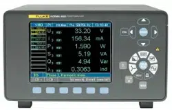
This chapter provides an overview of the terminals, ports and interfaces of the Fluke
NORMA 4000/5000 Power Analyzer (referred to throughout as “the Power Analyzer”). It
also includes a list of display and operating devices and a brief introduction to the basic
functions of the unit.
Terminals (Back)
Figure 3-1 illustrates the terminals on the back of the Power Analyzer. Table 3-1 is a list
of the terminal descriptions.
HI
VOLTAGE
1000 V max
LO
PROBE
EXT.SHUNT
10 V max
1
123 4
891011
56 712
23
HI
CURRENT
10 A max
LO
ALL INPUTS MAX 1000V CATII TO
PROBE
EXT.SHUNT
10 V max
HI
CURRENT
10 A max
LO
HI
VOLTAGE
1000 V max
LO
13
esn005.eps
Figure 3-1. Terminals
Table 3-1. Terminal Descriptions
Item Description
1
Measuring inputs for current (channels 1 to 6)
HI: Conductor, positive
LO: Conductor, negative
2 Measuring inputs for shunts (channels 1 to 6)
3
Measuring inputs for voltage (channels 1 to 6)
HI: Conductor, positive
LO: Conductor, negative
4 IEEE488 interface (optional)
5 Port for Analog Interface
6 Serial interface (RS232)
7
Power switch
I (on) and O (off)
8 Mains (power) connection
9 Input for external synchronization signal
10 IF1 network adapter (LAN) (optional)
11 Warning regarding maximum voltage to earth ground
12 Warning symbol: danger, observe operating instructions
13 Earth Ground
1.888.610.7664 sales@GlobalTestSupply.com
Fluke-Direct.com
Loading ...
Loading ...
Loading ...