Loading ...
Loading ...
Loading ...
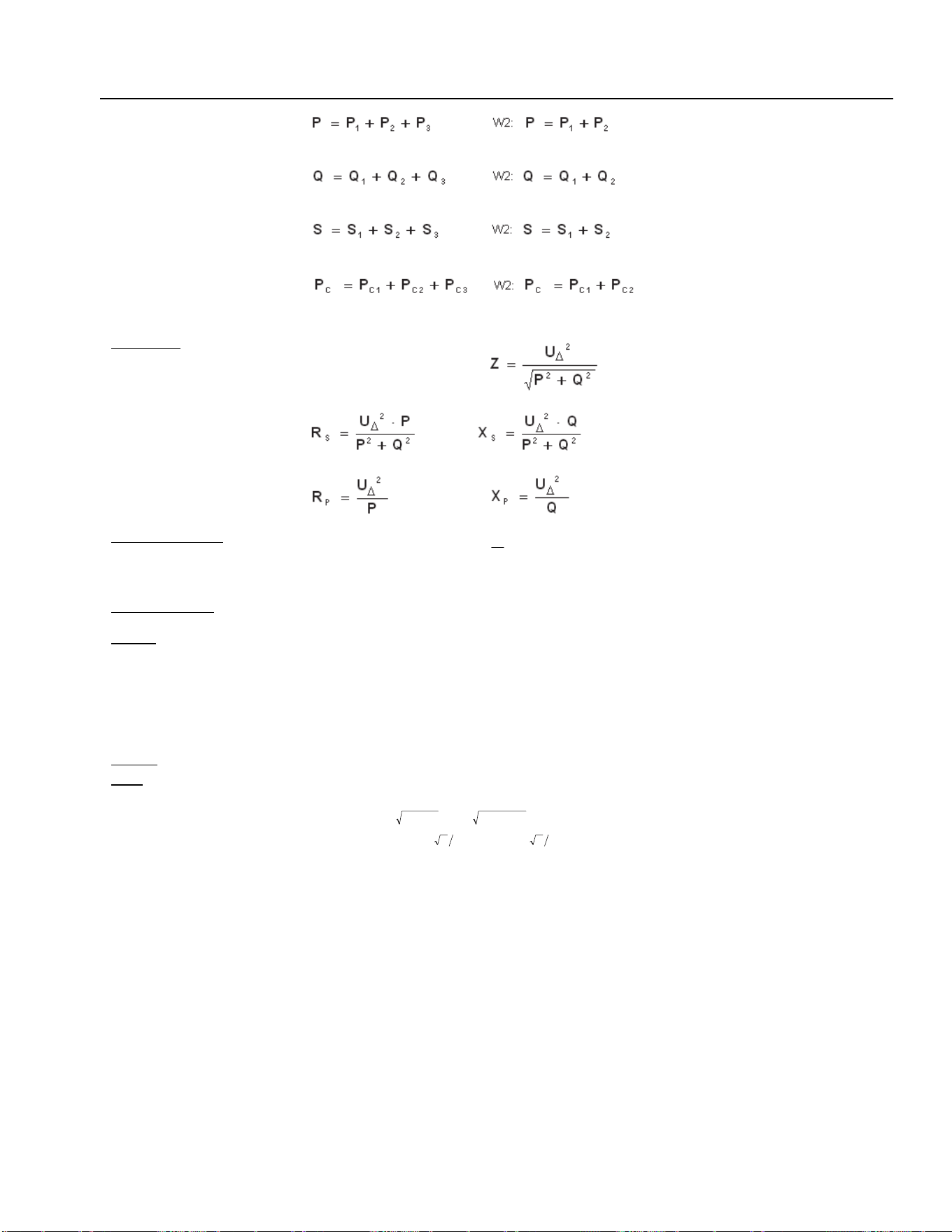
Measured Values Computation
10
10-5
Active power
Reactive power
[1]
Apparent power
[2]
Corrected power
[3]
Impedance
[4]
Serial components
Parallel components
Total power factor
S
P
=λ
Total phase shift
[5]
λ=ϕ arccos
Energy by the integration
function for P (separately
for positive and negative P)
⋅⋅= dtiuE
Frequency of the selected
channel
(voltage or current
1…3…6)
f
XU
or f
XI
Interval of measurement t
AVG
Time since start (reset) t
RAVG
Notes:
[1] Q1 and Q2 of a W2-system are internal values:
2
1
2
11
PSQ −=
,
2
2
2
22
PSQ −=
[2] S1 and S2 of a W2-system are internal values:
23IUS
1131
⋅⋅=
,
23IUS
2232
⋅⋅=
[3] The apparent power of W2 is calculated from 2 voltages and 2 currents in contrast to W3 system. This may lead to differences
between W3 and W2 measurements in case of unbalanced system/loads.
[4] The calculated values of total impedances represent average phase impedances on a symmetrical 3-wire wye-connected network
corresponding to the measured total phase-to-phase voltages U
Δ
and active and reactive power values P and Q.
[5] The phase shift ϕ for broad-band signals is in fact an artificial result. It conforms to a physical angle for sinusoidal signals only.
Often, it makes sense to use ϕ
H01
, the phase shift of the fundamental voltage to the fundamental current, instead.
1.888.610.7664 sales@GlobalTestSupply.com
Fluke-Direct.com
Loading ...
Loading ...
Loading ...