Loading ...
Loading ...
Loading ...
1760
Users Manual
3-8
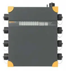
Check the respective option.
messsystem5 aron2-1.bmp
If option IL2 = -IL1 - IL3 is checked, the current IL2 is calculated. If this option is not
checked, the current IL2 is measured by means of a sensor connected to phase L2
(Instrument channel CH6).
The option Calculation of Events, Flicker, and Harmonics with delta voltage U12, U23
and U31 is automatically on and cannot be deactivated.
Note
The nominal voltage has to be entered as a phase-phase voltage in the
dialogue Nominal-Limit values (i.e. 400 V in a 230 V P-N-system).
Enter the applicable transformation ratios for the current and voltage
converters in the ‘Hardware Settings’ dialog.
As conventional current converters have an output current of 1 A or 5 A AC
respectively at rated current, we recommend using current probes rather
than flexible current sensors, as they provide better resolution and linearity
at low currents.
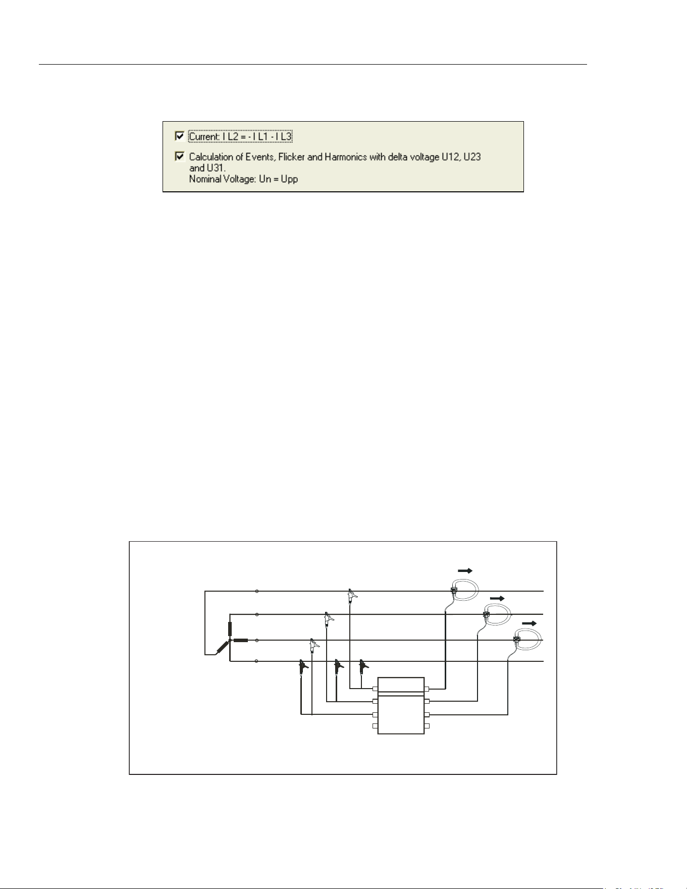
4-Wire Network: 3-Wattmeter Method
This is the standard measurement configuration for three-phase networks with 3 voltage
and 3 current sensors.
Figure 3-4 shows the circuit diagram for 4-wire network (Wye connection).
L1
L2
L3
PEN
Fluke 1760
LoadTransformer
Network
3wattm1.eps
Figure 3-4. Circuit Diagram: 4-Wire Network (Wye Connection)
1.888.610.7664 sales@GlobalTestSupply.com
Fluke-Direct.com
Loading ...
Loading ...
Loading ...