Loading ...
Loading ...
Loading ...
1760
Users Manual
3-6
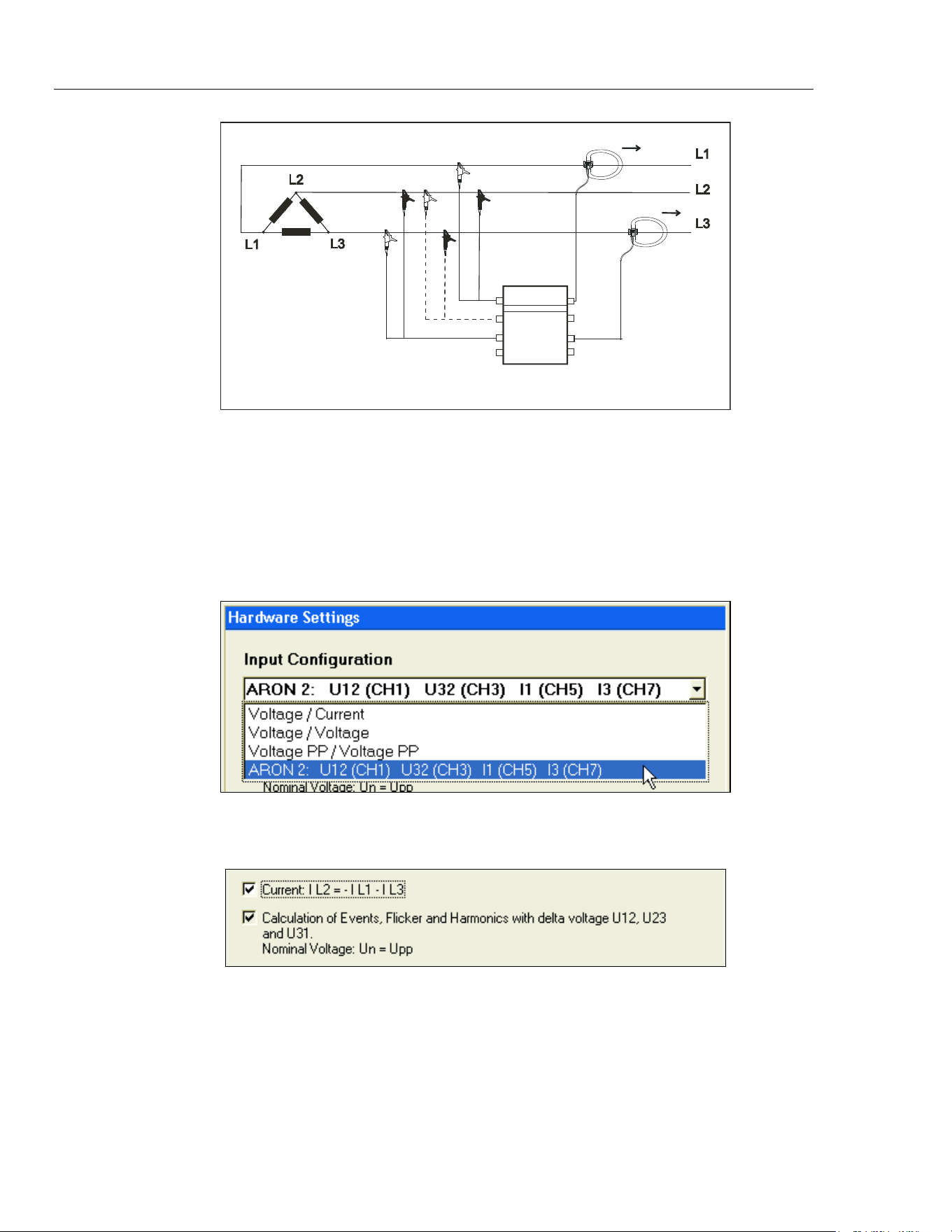
CH1 = U12
CH3 = U32
CH5 = I1
CH7 = I3
CH2 = U23
Fluke 1760
Load Transformer
2wattm1-aron2.eps
Figure 3-2. Circuit Diagram: 3-Wire Network (Aron 2)
Note
The voltage sensor at channel CH2 denoted with dotted lines is only
required for transient measurements; for current, voltage power
measurements, no sensor is required at CH2.
Associated Device Software Settings:
messsystem5 aron2.bmp
Check the respective option.
messsystem5 aron2-1.bmp
If the option IL2 = -IL1 - IL3 is checked, the current IL2 is calculated. If this option is not
checked, the current IL2 is measured by means of a sensor at phase L2 (Instrument
channel CH6).
Note
The nominal voltage has to be entered as a phase-phase voltage in the
dialogue Nominal-Limit values (i.e. 400 V in a 230 V P-N-system).
1.888.610.7664 sales@GlobalTestSupply.com
Fluke-Direct.com
Loading ...
Loading ...
Loading ...