Loading ...
Loading ...
Loading ...
Introduction
Design and Functions 1
1-13
These indicators provide information about the time synchronization of the Instrument.
LED PULSE:
This LED indicates the reception of sync pulses. If Instrument is synchronized correctly
the LED is green and flashes yellow for each pulse detected.
If external pulses are used without GPS time information the LED is off and flashes red
for each detected sync pulse (to enable this, the “Pulse” protocol must be selected in the
“Time Synchronization Configuration” in the PQ Analyze software).
LED DATA:
• Green: The Recorder is configured for time synchronization (Service menu), a
time synchronization adaptor (GPS or DCF77) is connected, and the received
time information is valid.
• Yellow: The Recorder is configured for time synchronization; a time
synchronization adaptor is connected, but the received time information is not
correct. Possible reasons: No satellites or time source found or adaptor still
synchronizing after power on.
• Red: The Recorder is configured for time synchronization, but no time
synchronization adaptor is connected or it is not working properly.
• Off: The recorder is not configured for time synchronization.
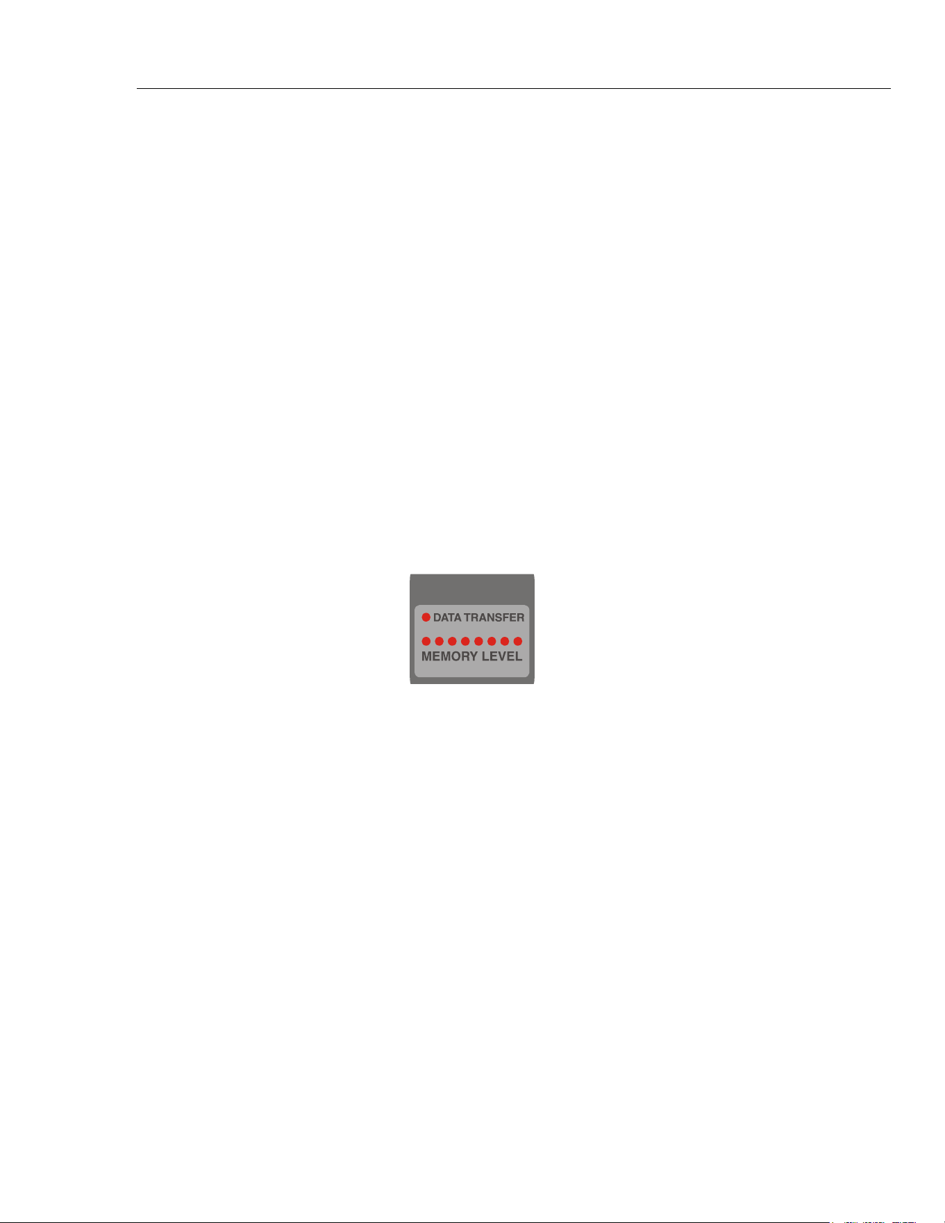
LEDs for Data Transfer and Storage:
led-data.wmf
LED DATA TRANSFER:
The DATA TRANSFER LED indicates data transfer via external interfaces or to the
Compact Flash card.
• Off: No connection between PQ Analyze software and Recorder exists.
• Green: Connection between PQ Analyze software and Recorder established.
• Flashing yellow: data are written to the internal CF-card, external CF-card, USB
memory stick or data transfer via any of the interfaces (USB, RS232, or Ethernet)
LEDs MEMORY LEVEL:
The row of MEMORY LEVEL LEDs indicates the amount of free/occupied
measurement data memory on the Compact Flash card.
Occupied blocks are indicated by lit LEDs, 5 on the left side are green, 3 on the right side
are red to indicate that the memory is soon full.
During a forced battery discharge these LEDs are flashing yellow, the number of LEDs
lit represents the remaining capacity in minutes.
1.888.610.7664 sales@GlobalTestSupply.com
Fluke-Direct.com
Loading ...
Loading ...
Loading ...