Loading ...
Loading ...
Loading ...
1760
Users Manual
3-4
Connection Diagrams
The measuring circuit is selected by means of the File > New / Hardware Settings menu
of the PQ Analyze software. Connect the sensors in load flow direction (observe arrows).
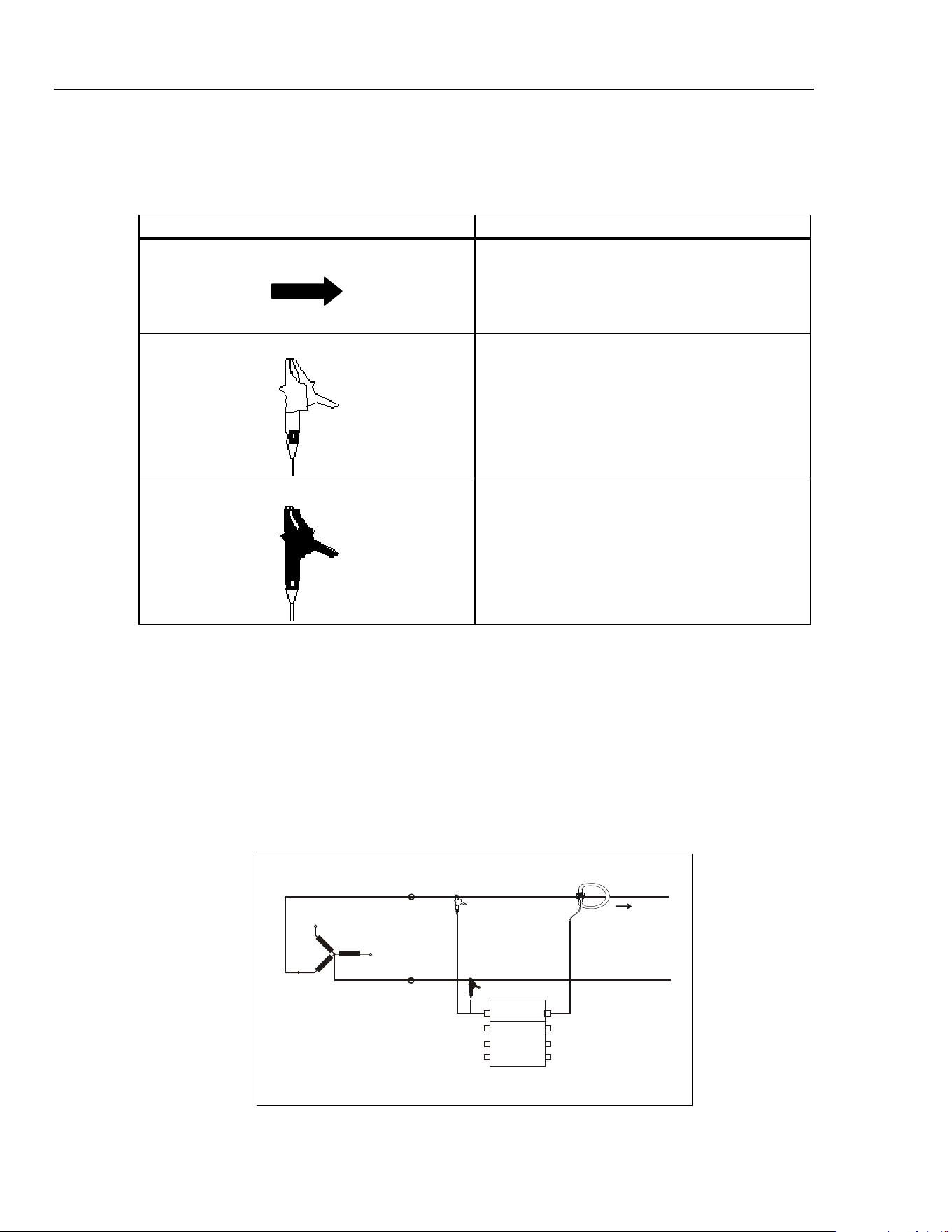
Table 3-1. Symbols in the Connection Diagrams
Symbol Meaning
Connect the Flexi current sensors in the right
direction.
The arrow on the Flexi must show from the network
to the load.
Red connector.
Black connector.
Note
Use channel ‘CH4’ as control channel for triggering on external signals.
Note
Fast voltage transients are always measured between the red plug of the
voltage sensor and the device ground (earth, protective conductor).
Please, note that the voltage sensors with a rated range of
>
100 V are
equipped with the fast transient function (if the transient option is installed).
1-Phase Measurement
Figure 3-1 shows the circuit diagram for 1-phase measurement.
L1
L2
L3
PEN
L1
Fluke 1760
Mains
Load
1wattm1.eps
Figure 3-1. Circuit Diagram: 1-Phase Measurement
1.888.610.7664 sales@GlobalTestSupply.com
Fluke-Direct.com
Loading ...
Loading ...
Loading ...