Loading ...
Loading ...
Loading ...
Operation
Connections to Measuring Circuits 3
3-5
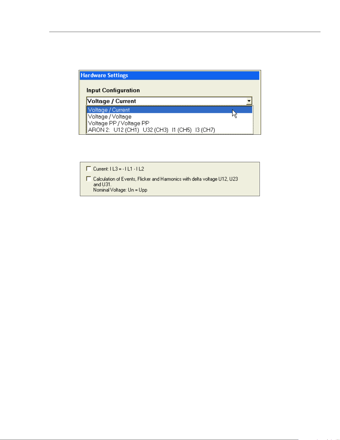
Associated PC software settings:
Connection to Single-Phase 2-Wire Network:
messsystem1 u-i.bmp
and
messsystem1 u-i-1.bmp
The option Calculation of Events, Flicker, and Harmonics with delta voltage U12, U23
and U31 for the phase-to-phase voltages is not of relevance here.
Note
All 8 channels are measured. Please keep this in mind when assessing the
power quality according to EN 50160.
To avoid false triggering, please switch channels that are not connected to
“OFF” in the “Hardware Settings” configuration panel.
3-Wire Network with Two Current Sensors (ARON2 Method)
Conventional two-wattmeter method with current sensors on phases L1 and L3.
The device calculates IL2 = -IL1 – IL3. Two phase-to-phase voltages (U12 U32) are
measured. The third phase-to-phase voltage (U23) is calculated. The recorder then
transforms this delta system into a virtual Wye system by calculating virtual phase
voltages. This virtual Wye system is in turn used to calculate the power values of all three
phases as well as the total power. This method is applicable only if I1 + I2 + I3 =0, i.e. if
there is no neutral conductor.
Figure 3-2 shows the circuit diagram for 3-wire network (Aron 2).
1.888.610.7664 sales@GlobalTestSupply.com
Fluke-Direct.com
Loading ...
Loading ...
Loading ...