Loading ...
Loading ...
Loading ...

Introduction
Design and Functions 1
1-17
stecker lpt.wmf
Pin assignment:
Pin Signal Description
1 +15 V Power supply voltage, max. 300 mA
2 TxD Output, Transmit Data COM2
3 RxD Input, Receive Data COM2
4 RTS Output, Request to send COM2
5 CTS Input, Clear to Send COM2
6 Service Output, internal use
7 GND Signal ground
8 Service Output, internal use
9 Watchdog Pulse Output, CPU watch dog signal
10 O1 Alarm output, reset with input RES 1
11 O2 Alarm output, reset with input RES 1
12 O3 Alarm output, reset with input RES 2
13 O4 Alarm output, reset with input RES 2
14 +5 V Power supply voltage
15 GPS PPS+ Input for GPS time synchronization
16 GPS PPS − Input for GPS time synchronization
17 GPS Transmit+ Input for GPS time synchronization
18 GPS Transmit- Input for GPS time synchronization
19-23 Service Output, internal use
24 RES1 Reset input for alarm outputs O1, O2
25 RES2 Reset input for alarm outputs O3, O4
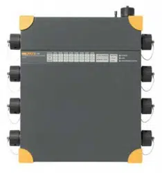
H Measurement Channels
Plugs for 8 isolated measurement channels. Connect only original accessories such as
voltage and current sensors (clamps, Flexi Set, shunt resistors, etc.). The plug is secured
by means of a bayonet mechanism.
Note
Inputs that are not in use must be covered with the supplied protective caps
to prevent pollution.
When analyzing transients with 500 kHz transient option or 10 MHz
transient option, the potential to earth/ground is measured.
1.888.610.7664 sales@GlobalTestSupply.com
Fluke-Direct.com
Loading ...
Loading ...
Loading ...