Loading ...
Loading ...
Loading ...

14
3. Installation and Wiring
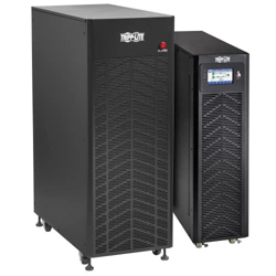
Figure 3-4: Front and Rear Views of 15kVA / 20kVA UPS (terminal block shown without cover)
1
LCD Panel
2
Accessory Slot
3
SNMP Port
4
Backfeed Dry Contacts
5
POWER Switch (Remove cover to access switch)
6
USB Port
7
Two RS-485 Ports
(MODBUS or Battery Thermostat)
8
RS-232 Port
9
Output Breaker
10
Maintenance Breaker (shown uncovered)
11
Bypass Breaker
12
Terminal Block for Input, Output & GND
13
EVENTS (Service Port)
14
REPO Port
15
Parallel Port 1
16
Parallel Port 2
17
Cold Start Button
18
Input Breaker
19
Terminal Block for Battery
1
2
4
6
8
9
10
11
12
13
17
15
18
14
16
19
3
5
7
Loading ...
Loading ...
Loading ...