
Loading ...
Loading ...
Loading ...
Part number 550-100-211/0122
– 99 –
220 /29 9/3 00 /39 9
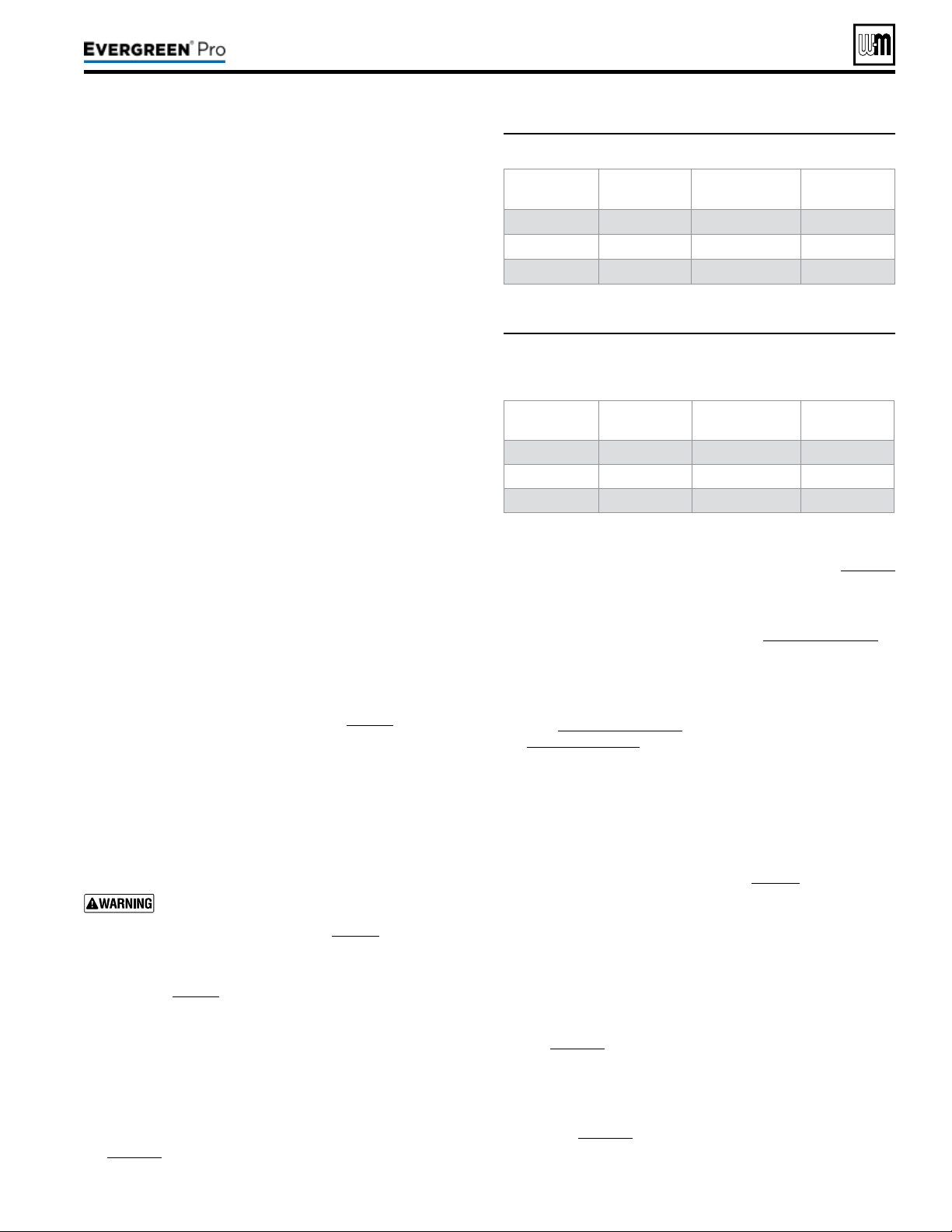
Figure94 Minimum ame signal values during operation
Model Minimum
amesignal
Model Minimum
amesignal
EVG 220
100 EVG 220 LP 100
EVG 299/300 100 EVG 299/300 LP 100
EVG 399 124 EVG 399 LP 100
Figure95 Flame signal shut down values — the control
will shut the boiler down if ame signal levels
drop below the values below
Model Shutdown
amesignal
Model Shutdown
amesignal
EVG 220
80 EVG 220 LP 80
EVG 299/300 80 EVG 299/300 LP 80
EVG 399 104 EVG 399 LP 80
(continued)
1. Inspect all boiler wiring, making sure wires are in good condi-
tion and securely attached.
2. Verify that all connectors are securely inserted.
3. Verify ground wires are connected to jacket right side and
control tray cover.
1. Use the Control display to navigate through all settings. Adjust
settings if necessary.
2. Check settings of external limit controls (if any) and adjust
if necessary. Adjust as needed to accommodate the system
design.
1. Inspect pressure switch, ensuring wire connects are properly
connected and tube is secured to pressure port.
2. Inspect tube for any signs of damage or debris collected in
tube, replace if necessary.
3. Aer checking Control Settings (see above), disconnect tube
connection with condensate dish. Gently blow on tube until
pressure switch opens and control displays lockout error.
Clear lockout on control and conrm that lockout does not
re-appear. Reconnect tube connection with condensate dish,
making sure connection is secure.
1. Start boiler and perform checks and tests specied in this
manual.
2. Verify cold ll pressure is correct and that operating pressure
does not go too high. Adjust water pressure and expansion
tank charge pressure as necessary.
3. Complete the check-out procedure on page92.
1. If the low water cuto amber LED is on, the LWCO requires
service.
2. Follow the manufacturer’s instructions packed with the low
water cut-o (shipped as standard equipment with all Ever-
green boilers, in the kit box).
The boiler contains ceramic fiber materi-
als. Use care when handling these ma-
terials per instructions on page94 of this manual.
Failure to comply could result in severe personal injury.
1. Inspect ame through observation window using the pro-
cedure on page90.
2. If ame is unsatisfactory at either high re or low re, check
combustion values. If combustion is properly adjusted, turn
o boiler and allow boiler to cool down. en remove burner
and clean it thoroughly using a vacuum cleaner or compressed
air. Do not use compressed air to clean burner if performed
inside a building.
3. To access the burner, remove the burner access panel and
the cover plate top following the procedure beginning on
page111.
4. If removing the cover plate top and /or the burner, the burner
gasket must be replaced. Follow all instructions on page114
to reinstall all components.
5. Restart the boiler.
6. Inspect the ame at high and low re. If ame is still not
acceptable, check combustion values, Figure89,page91. If
combustion can not be properly adjusted, obtain a replace-
ment burner from Weil-McLain.
7. Check ame signal at both high re and low re.
8. Navigate to Diagnostics/Inputs on the Control display
(see Figure74,page75 for navigation instructions and
Figure80,page80 for the complete Diagnostics menus).
9. e ame signal value must be at least equal to the values
listed in Figure94.
10. If the ame signal drops below this level, the Control will
attempt to correct by increasing the boiler ring rate to in-
crease ame signal.
11. A low ame signal may indicate a fouled ame sense rod.
a. See “Inspect Flame Sense Rod,” page97to remove and
inspect the ame sense rod.
b. If required, clean the ame sense rod as instructed.
c. Check combustion values.
d. If cleaning the ame sense rod does not improve, ame
sense wiring is in good condition, and ground continuity
is satisfactory, replace the ame sense rod.
12. If ame signal still remains low:
a. See “Remove, Inspect and Clean the Burner,” see
page111 to remove and replace burner gasket.
b. Inspect the vent and air piping.
c. en inspect the heat exchanger, following the procedures
given in this manual for removal and reinstallation of the
heat exchanger cover plate and other boiler components
(see page111).
d. Clean the exchanger as described in this manual if nec-
essary.
Loading ...
Loading ...
Loading ...