is manual must only be used by a qualied heating installer/service technician. Read all instructions, including this manual and
all other information shipped with the boiler, before installing. Perform steps in the order given. Failure to comply could result in
severe personal injury, death or substantial property damage.
• Installation
• Startup
• Maintenance
• Parts
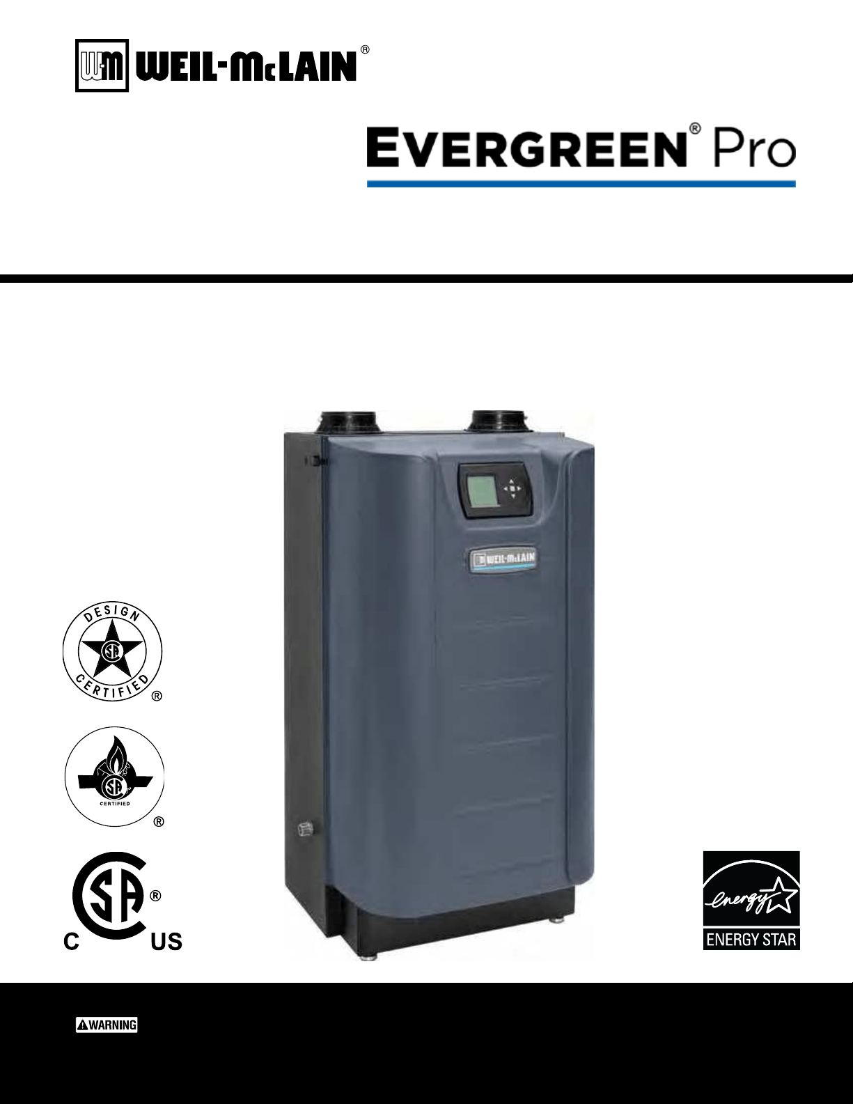
Boiler Manual
Part number 550-100-211/0122
CONDENSING GAS BOILER
220/299/300/399

T he Eve rgreen
®
Part number 550-100-211/0122
– 2 –
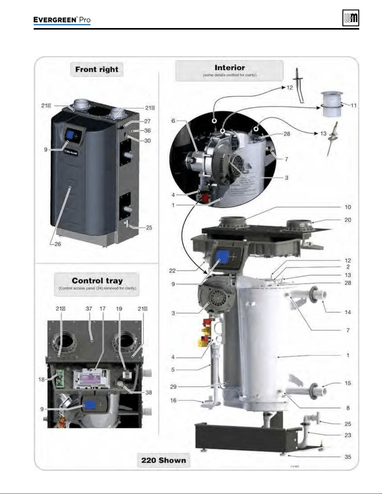
1. Stainlesssteelretubeheatexchanger
2. Burneraccesscover/heatexchangercoverplate
3. Blower
e advanced blower design and air inlet silencer on Evergreen
®
boilers
result in very quiet operation.
Air enters the boiler enclosure through the air intake adapter (Item 20), ows through
the enclosure, enters the air inlet silencer (Item 5), then enters the venturi (Item 6)
where it mixes with gas before entering the blower. e blower pulls air through these
components and then pushes it through the cover plate to the burner (Item 11).
4. Gasvalve
e automatic gas valve references the pressure in the Evergreen
®
cabinet and allows
gas to ow when the control (Item 17) applies power. A manual gas valve is shipped
loose with the boiler. It allows shutting o the gas supply for servicing or shut down.
See instructions in this manual for manual gas valve installation.
5. Airinletsilencer
The horn-shaped air inlet silencer significantly reduces fan noise, providing
exceptionally quiet operation.
6. Venturi
When air ows through the venturi, a negative pressure is created. is causes gas to
ow from the gas valve into the venturi, where it is mixed with the air. e gas/air
mixture then continues into the blower.
7. Outletwatertemperaturedualsensor
is dual sensor monitors boiler outlet water temperature. e control adjusts boiler
ring rate so the outlet water temperature is correct, based on the calculated (if outdoor
reset used — seepage129) or xed target temperature.
8. Returnwatertemperaturesensor
is sensor monitors return water temperature. e control reduces or increases boiler
input, depending on how close the return water temperature is to the outlet water
temperature.
9. Electronicdisplay&interfacebuttons
e electronic display is used to congure boiler settings and monitor boiler operation.
e buttons allow changing display mode, selecting and adjusting control settings, and
resetting the control aer lockout.
10.Flueadapter(ts4”PVC)
11.Burner
e high-grade stainless steel burner uses pre-mixed air and gas to provide a modulat-
ing ame to the heat exchanger.
12.Ignitionelectrode
e burner ame is ignited by applying a high voltage to the ignition electrode. is
causes a spark from the electrode to ground.
13.Flamesenserod
Aer ignition, this measures the ame signal to provide a safe combustion at all times.
14.Wateroutletpipe(supply)(1½”NPT)
15.Waterinletpipe(return)(1½”NPT)
16. Gas line
is stainless steel exible gas line connects the incoming gas line to the gas valve.
e gas line has a ¾”NPT connection for installation.
17.Evergreen
®
control(seediscussionupperright)
18.Circulator/CommunicationBoard
e circulator/communication board provides boiler-to-boiler communication,
Building Management System (BMS) interface, and 120VAC power for the boiler
loop circulator.
19. Transformer
e 120VAC/24VAC transformer provides 24VAC to low voltage control circuitry.
Do NOT splice wiring into transformer.
20.Airintakeadapter(ts4”PVC)
21a&21b.Electricalentrances
e four (4) knockouts on the le side of the control tray are intended for low voltage
and boiler pump wiring, and the four knockouts on the right side are intended for
the line voltage and three high voltage outputs from the control.
22.Airpressureswitch
Air pressure switch monitors air ow by sensing changes in pneumatic pressure.
23.Fluegascondensatedrain
Connect the boiler internal condensate trap line to the heat exchanger here (parts
supplied with boiler, but eld installed).
24.Controlaccesspanel(notshown)
Remove when power is o to access the control.
25.Fluegascondensatedrainconnection
e condensate trap PVC ttings are eld-installed, connected to the condensate trap
line as shown in this manual.
26.Frontdoor
e front door is sealed to the boiler assembly around its entire perimeter.
27.Frontdoorlatches
Two latches secure the door in place.
28.Flameinspectionwindow
e quartz glass window provides a view of the burner surface and the ame.
29.Fluegasdualsensor
is dual sensor monitors the ue gas exit temperature. e control will shut down
the boiler if ue gas temperature gets too hot. is protects the ue pipe and the heat
exchanger from overheating.
30.ON/OFFswitch
31.Boilerdrainvalve(notshown)
Shipped loose for eld installation. See instructions in this manual.
32.Boilerreliefvalve(notshown)
Shipped loose for eld installation. See instructions in this manual.
33.Boilerpressure/temperaturegauge(notshown)
Shipped loose for eld installation. See instructions in this manual.
34.Manualgasshutoffvalve(notshown)
Shipped loose for eld installation. See instructions in this manual.
35.LevelingLegs
e leveling legs are adjustable to level the boiler.
36.Receptacle
e receptacle can be used for a condensate pump 2 amp maximum.
37.Toppanelhatch
Remove this panel when removing the burner.
38.Controltrayinspectionwindow
Provides a better view of the burner and ame.
Evergreen
®
controloverview
y e Evergreen
®
control can operate a single boiler or coordi-
nate with other Evergreen
®
boilers in a multiple boiler system.
y Control inputs and outputs allow operation of multiple heat-
ing circuits (space heating and DHW, for example).
y Up to three priority levels can be set, providing automatic
switch-over on demand.
y is manual provides quick set-up information for single
boiler installations.
y e Advanced Manual, available at Weil-Mclain.com, pro-
vides instructions for setting up multiple-boiler systems and
for using advanced options for single boilers.
Evergreen
®
controloperation
y e control responds to signals from the room thermostats,
DHW aquastats (if used), boiler sensors (boiler return, boiler
supply, ue temperature), outdoor temperature and system
sensor, if used.
y e control automatically adjusts blower speed (and gas ow
rate) to match boiler output to space heating and/or DHW
heating demand.
y e default control settings provide for three space heating
zones. e control can be easily set up for operation with a
DHW zone, with or without domestic priority.
Evergreen
®
controlWIZARD
y e control setup Wizard is available from the BOILER
SETTINGS menu that appears during initial startup.
y e Wizard leads through a step-by-step setup procedure
designed for the application chosen.
y Context-sensitive help is available to explain the purpose of
key setup items.
220 /29 9/3 00 /39 9
T he Eve rgreen
®
(continued)
Line voltageLow voltage
Part number 550-100-211/0122
– 3 –
220 /29 9/3 00 /39 9

Part number 550-100-211/0122
– 4 –
The Evergreen® Gas-red water boilers. . . . . . . . . . . . . 2
Please read before proceeding . . . . . . . . . . . . . . . . . . 5
Boiler location . . . . . . . . . . . . . . . . . . . . . . . . . . .6
Prepare boiler location . . . . . . . . . . . . . . . . . . . . . . 8
Wall-mounting the boiler . . . . . . . . . . . . . . . . . . . . . 8
Boiler hydrostatic test. . . . . . . . . . . . . . . . . . . . . . 10
Gas conversions. . . . . . . . . . . . . . . . . . . . . . . . . 12
Gas piping — sizing gas lines . . . . . . . . . . . . . . . . . 18
Venting/air piping — general . . . . . . . . . . . . . . . . . . 19
Commonwealth of Massachusetts installations. . . . . . . . 22
Vent termination requirements . . . . . . . . . . . . . . . . . 23
Boiler room air openings . . . . . . . . . . . . . . . . . . . . 24
DIRECT VENT — Sidewall with separate pipes . . . . . . . . 25
DIRECT VENT — Sidewall with W-M vent/air plate . . . . . . 27
DIRECT VENT — Sidewall concentric . . . . . . . . . . . . . 29
DIRECT VENT — Vertical with separate pipes. . . . . . . . . 31
DIRECT VENT — Vertical concentric. . . . . . . . . . . . . . 33
Concentric termination, typical (sidewall or vertical) . . . . . 35
DIRECT VENT — Vertical vent / sidewall air . . . . . . . . . . 36
Vent and air piping and boiler connections . . . . . . . . . . 38
Install water piping . . . . . . . . . . . . . . . . . . . . . . . 39
Expansion tank . . . . . . . . . . . . . . . . . . . . . . . . . 42
Install condensate line . . . . . . . . . . . . . . . . . . . . . 49
Gas piping . . . . . . . . . . . . . . . . . . . . . . . . . . . . 51
Field wiring. . . . . . . . . . . . . . . . . . . . . . . . . . . . 52
Wiring diagram — schematic . . . . . . . . . . . . . . . . . . 59
Wiring diagram — ladder . . . . . . . . . . . . . . . . . . . . 60
Zoning with the EVG Control . . . . . . . . . . . . . . . . . . 61
Evergreen Control operation . . . . . . . . . . . . . . . . . . 63
EXPRESS SETUP — Example A . . . . . . . . . . . . . . . . 68
EXPRESS SETUP — Example B . . . . . . . . . . . . . . . . 70
EXPRESS SETUP — Example C . . . . . . . . . . . . . . . . 72
Available control settings and system presets . . . . . . . . 74
CONTRACTOR menus . . . . . . . . . . . . . . . . . . . . . 75
BOILER SETTINGS menu, BASIC mode . . . . . . . . . . . . 76
PRIORITY 1, 2, 3 menus, BASIC mode . . . . . . . . . . . . . 77
ASSIGN INPUTS menu, BASIC mode . . . . . . . . . . . . . 78
DIAGNOSTIC menu . . . . . . . . . . . . . . . . . . . . . . . 80
MAINTENANCE, DATE AND TIME menus . . . . . . . . . . . 85
Startup — ll the system . . . . . . . . . . . . . . . . . . . . 86
Startup — nal checks . . . . . . . . . . . . . . . . . . . . . 88
Check-out/startup verication . . . . . . . . . . . . . . . . . 92
Annual startup and general maintenance . . . . . . . . . . . 93
Annual startup . . . . . . . . . . . . . . . . . . . . . . . . . . 94
Manual Test Mode for Single and Multiple Boilers . . . . . .101
Troubleshooting . . . . . . . . . . . . . . . . . . . . . . . . .102
Maintenance . . . . . . . . . . . . . . . . . . . . . . . . . . .110
Cleaning heat exchanger ue side . . . . . . . . . . . . . . . 111
Replacement parts . . . . . . . . . . . . . . . . . . . . . . . 116
Dimensions . . . . . . . . . . . . . . . . . . . . . . . . . . .128
Ratings . . . . . . . . . . . . . . . . . . . . . . . . . . . . . .129
Ratings — Multiple boilers . . . . . . . . . . . . . . . . . . .130
Installation and Service Certicate. . . . . . . . . . . . . . .131
Installation and Gas Boiler Data Collection Sheet . . . . . .132
DO NOT SERV I CE T H E BOI LER
WI THOUT A Eve rgre e n
®
MAINTENAN CE K I T AVAILABLE
e Evergreen
®
maintenance kit includes components that
may have to be replaced when accessing or disassembling
parts of the boiler. Failure to replace damaged components
and to use only the parts specically intended for the boiler
can result in severe personal injury, death or substantial
property damage. See Figure111,page117 for part number.
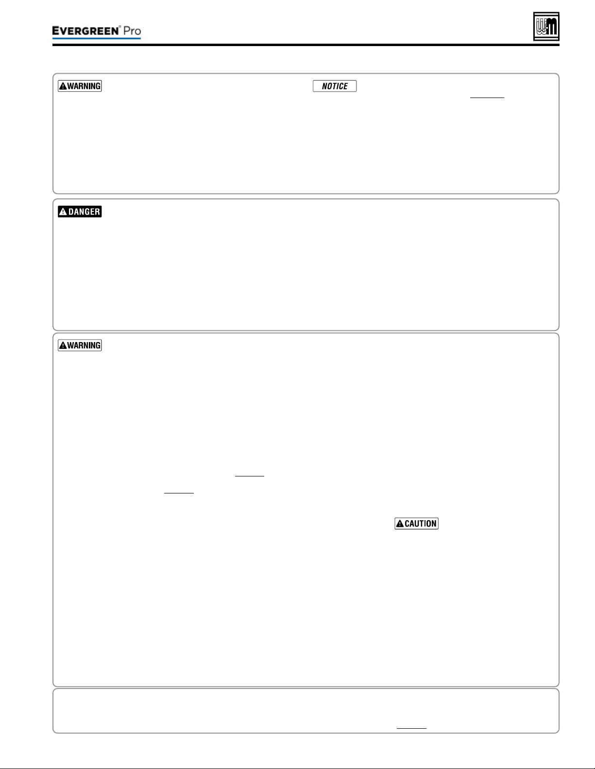
e following dened terms are used throughout this manual to bring attention to the presence of hazards of various risk levels
or to important information concerning the life of the product.
Indicates presence of hazards that will cause
severe personal injury, death or substantial
property damage.
Indicates presence of hazards that can cause
severe personal injury, death or substantial
property damage.
Indicates presence of hazards that will or can
cause minor personal injury or property damage.
Indicates special instructions on installation,
operation or maintenance that are important
but not related to personal injury or property
damage.
220 /29 9/3 00 /39 9
Part number 550-100-211/0122
– 5 –
220 /29 9/3 00 /39 9
Failuretoadheretotheguidelinesbelowcanresultinseverepersonalinjury,deathorsubstantialpropertydamage.
EXPANSIONTANK
Relieve pressure from the system before
isolating the expansion tank.
Whenservicingboiler—
y To avoid electric shock, disconnect all
electrical supplies to the boiler before
performing maintenance.
y To avoid severe burns, allow boiler to
cool before performing maintenance.
y is boiler contains ceramic ber and
berglass materials. Refer to the WARN-
ING and instructions on page94.
Boileroperation—
y Do not block ow of combustion or
ventilation air to boiler.
y Should overheating occur or gas supply
fail to shut o, do not turn o or discon-
nect electrical supply to pump. Instead,
shut off the gas supply at a location
external to the appliance.
Combustionair—
y DO NOT install combustion air intake
where there is a risk of combustion air
contamination.
Carbonmonoxidedetector—
y A carbon monoxide detector that is
wired on the same electrical circuit as
the boiler is strongly recommended.
SURGEPROTECTOR—
y Provide surge protection in the boiler
power supply. is will reduce the pos-
sibility of damage to the boiler control.
Boilerwater—
y e Evergreen heat exchanger is made
of stainless steel, and requires that sys-
tem water chemistry be within the limits
in this manual. ADDITIONALCHEMICAL
TREATMENTMAYBENECESSARY
. See
page86 for details.
y oroughly ush the system (BEFORE
connecting boiler) to remove sediment.
e high-eciency heat exchanger can
be damaged by build-up or corrosion
due to sediment.
y Do not use petroleum-based cleaning
or sealing compounds in boiler system.
Gaskets and seals in the system may be
damaged. is can result in substantial
property damage.
y Continual fresh make-up water will
reduce boiler life. Mineral buildup in
eat exchanger reduces heat transfer,
overheats the stainless steel heat ex-
changer, and causes failure. Addition of
oxygen carried in by make-up water can
cause internal corrosion. Leaks in boiler
or piping must be repaired at once to
prevent make-up water. Use this boiler
ONLY in a closed-loop system.
y Do not add cold water to a hot boiler.
ermal shock can cause heat exchanger
to crack.
Freezeprotectionuids—
y NEVER use automotive or standard
glycol antifreeze. Use only freeze-
protection fluids made for hydronic
systems. Follow all guidelines given
by the antifreeze manufacturer. or-
oughly clean and ush any replacement
boiler system that has used glycol before
installing the new boiler
Frozen Water Damage
Hazard
Residences or buildings that are unat-
tended in severely cold weather, boiler
system components failures, power out-
ages, or other electrical system failures
could result in frozen plumbing and water
damage in a matter of hours. For your
protection, take preventative actions such
as having a security system installed that
operates during power outages, senses low
temperature, and initiates an eective ac-
tion. Consult with your boiler contractor
or a home security agency.
Ifanypartofaboiler,burneroritscontrolshas
beensprayedwithorsubmergedunderwater,
eitherpartiallyorfully,DONOTattempttoop-
eratetheboileruntiltheboilerhasbeeneither
replacedorcompletelyrepaired,inspected,and
youaresurethattheboilerandallcomponents
areingoodconditionandfullyreliable.
Otherwise, by operating this boiler, you will
cause a re or explosion hazard, and an electrical
shock hazard, leading to serious injury, death, or
substantial property damage. See the instructions
at right.
Saltwater Damage — e exposure of boiler components to
saltwater can have both immediate and long-term eects. While the
immediate eects of saltwater damage are similar to those of fresh-
water (shorting out of electrical components, washing out of critical
lubricants, etc.), the salt and other contaminants le behind can lead
to longer term issues aer the water is gone due to the conductive
and corrosive nature of the salt residue. erefore, Weil-McLain
equipment contaminated with saltwater or polluted water will no
longer be covered under warranty and should be replaced.
ElectricalDamage — If any electricalcomponent or wiring came
into contact with water, or was suspected to have come into contact
with water, replace the boiler with a new Weil-McLain boiler.
When the boiler is installed within the Commonwealth of Massachusetts:
y is product must be installed by a licensed plumber or gas tter.
y If antifreeze is used, a reduced pressure back-ow preventer device shall be used.
y Sidewall vent air installations — see instruction on page22.
Installer— Read all instructions, including this
manual and all other information shipped with the
boiler, before installing. Perform steps in the order
given.
User— is manual is for use only by a qualied
heating installer/service technician. Refer to User’s
Information Manual for your reference.
User — Have this boiler serviced/inspected by a
qualied service technician, at least annually.
Failure to comply with the above could result in severe
personal injury, death or substantial property damage.
Write in the CP number in the space provided on
the Installation certicate on page131 if not already
shown.
When calling or writing about the boiler— Please
have the boiler model number from the boiler rating
label and the CP number from the boiler jacket.
Consider piping and installation when determining
boiler location.
Any claims for damage or shortage in shipment
must be led immediately against the transportation
company by the consignee.

Part number 550-100-211/0122
– 6 –
y Local, state, provincial, and national codes, laws, regulations
and ordinances.
y National Fuel Gas Code, ANSI Z223.1/NFPA 54 - latest
edition.
y National Electrical Code.
y For Canada only: CAN/CSA B149.1, Natural Gas and Pro-
pane Installation Code, and any local codes.
e Evergreen
®
boiler gas manifold and controls
met safe lighting and other performance criteria
when boiler underwent tests specied in ANSI
Z21.13 — latest edition.
1. e boiler must not be installed on carpeting.
Do not install boiler on carpeting even if founda-
tion is used. Fire can result, causing severe personal
injury, death or substantial property damage.
2. e boiler is suitable for INDOOR installation only.
3. Check for nearby connection to:
y System water piping
y Venting connections
y Gas supply piping
y Electrical power
y Condensate drain
4. Check area around boiler. Remove any combustible materials,
gasoline and other ammable liquids.
Failure to keep boiler area clear and free of com-
bustible materials, gasoline and other ammable
liquids and vapors can result in severe personal
injury, death or substantial property damage.
5. e boiler must be installed such that the gas ignition system
components are protected from water (dripping, spraying,
rain, etc.) during appliance operation and service (circulator
replacement, condensate trap, control replacement, etc.).
6. If new boiler will replace existing boiler, check for and correct
system problems, such as:
y Sediment or corrosion in system piping — clean and ush
piping BEFORE connecting the new boiler. See page86.
y System leaks causing oxygen corrosion or heat exchanger
cracks from hard water deposits.
y Incorrectly-sized expansion tank.
y Lack of freeze protection in boiler water causing system
and boiler to freeze and leak.
Precautions
1. Take the following special precautions when installing the
boiler in a residential garage. If the boiler is located in a
residential garage:
y Mount the boiler with its bottom at least 18inches above
the oor. is complies with the National Fuel Gas Code,
ANSI Z223.1 NFPA 54 -latest edition for U. S. installa-
tions, or
Natural Gas and Propane Installation Code,
CAN/CSA
B149.1 and B149.2 for Canadian installations.
y Locate or protect the boiler so it cannot be damaged by
a moving vehicle.
y Ensure that the installation complies with all applicable
codes.
y Prevent boiler water and condensate from freezing.
Evergreen
®
boileraloneinboilerroom
(DirectVent)
1. No air ventilation openings into boiler room are needed if
clearances around Evergreen
®
boiler are at least equal to the
SERVICE clearances shown in Figure1,page7.
2. For spaces that DO NOT supply the minimum service clear-
ances, provide two openings as shown in Figure1,page7.
Each opening must provide 1square inch free area per 1,000
Btuh of boiler input.
Evergreen
®
boilerinsamespacewithothergas
oroil-redappliances
1. Follow the sizing requirements shown in Figure26,page24.
e space must be provided with combustion/
ventilation air openings correctly sized for all
appliances located in the same space as the
Evergreen
®
boiler.
Reinstall boiler jacket front door aer servic-
ing. e boiler front door must be securely
fastened to the boiler to prevent boiler from
drawing air from inside the boiler room. is
is particularly important if the boiler is located
in the same room as other appliances.
Failure to comply with the above warnings
could result in severe personal injury, death
or substantial property damage.
1. e Evergreen
®
boiler requires a special vent system, designed
for pressurized venting. Evergreen
®
boilers are rated ANSI
Z21.13 Category IV (pressurized vent, likely to condense in
the vent). See instructions beginning on page19.
2. You must also install air piping from outside to the boiler
air intake adapter. e resultant installation is categorized as
direct vent (sealed combustion). Note prevention of combus-
tion air contamination on page19 when considering vent/
air termination.
3. Vent and air must terminate near one another unless oth-
erwise specied in this manual. Vent and air piping may be
routed vertically through the roof or out a side wall, following
the options give in this manual. You may use any of the vent/
air piping methods covered in this manual. Do not attempt
to install the boiler using any other means.
4. Be sure to locate the boiler such that the vent and air piping
can be routed through the building and properly terminated.
e vent/air piping lengths, routing and termination method
must all comply with the methods and limits in instructions
beginning on page19.
220 /29 9/3 00 /39 9
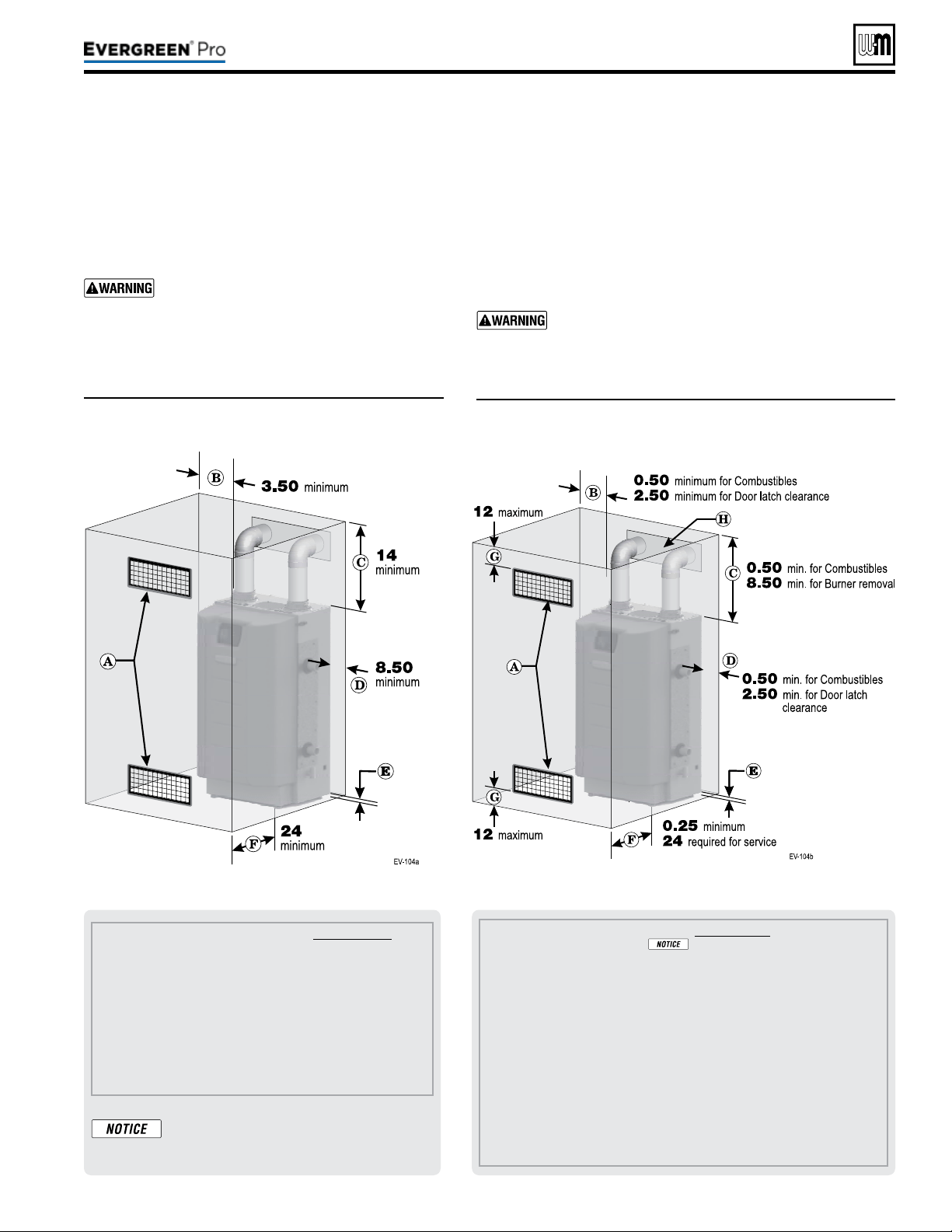
Figure2 REQUIRED minimum clearances
(
alldimensionsareininches)
Figure1 RECOM M ENDED service clearances
(
alldimensionsareininches)
Part number 550-100-211/0122
– 7 –
220 /29 9/3 00 /39 9
A Provide combustion air/ventilation openings per Figure 26, page 24 or as otherwise directed in
this manual or by applicable codes.
If the installation does not provide the minimum
clearances in Figure 1, then the enclosure MUST HAVE air openings located per Figure 2,
above. Each of these air openings must have free area of at least 1 square inch per 1,000
MBH of boiler input.
B Left side clearance to combustibles = 0.50 inches minimum, but 2.5” for door latch removal.
C Top of boiler clearance to combustibles = 0.50 inches minimum, but 8.5” for burner removal.
D Right side clearance to combustibles = 8.50 inches minimum, but 2.5” for door latch removal.
E Bottom of boiler clearance to combustibles = 0 inches minimum (must be 18 inches above
oor for garage installations).
F Clearance in front of the boiler = 0.25 inches, but 24 inches minimum required for service.
G Air openings must be located in the FRONT of the enclosure, as shown. They must be no
more than 12 inches from the oor or ceiling, as shown.
H Vent pipe must be minimum 3/16 inch from combustibles. Opening in combustible wall, oor,
ceiling or roof must be 3/8” larger than ue pipe diameter, tted with galvanized steel thimble,
or larger if required by codes or as specied by vent pipe manufacturer.
A Provide combustion air/ventilation openings per Figure 26, page 24 or as
otherwise directed in this manual or by applicable codes. NOTE: If the
installation does not provide the minimum clearances in this illustration,
then the enclosure must have air openings located and sized per Figure 2.
B Left side service clearance =
3.50 inches minimum.
C Service clearance above top of boiler = 14 inches minimum.
D Right side service clearance = 8.50 inches minimum.
E Service clearance below the boiler = 0 inches minimum.
F Service clearance in front of the boiler = 24 inches minimum.
ADDITIONAL service clearance may
be needed, depending on how piping
is routed to the boiler.
1. See Figure1 for recommended service clearances.
2. If you do not provide minimum service clearances
shown, it might not be possible to service the boiler
without removing it from the space.
Closet or small-enclosure installations
whichdonotprovideatleasttheserecom-
mendedclearancesrequirethespecially-
sized and placed air openings shown in
Figure2
.
1. See Figure2 for REQUIRED minimum clearances. ALL installa-
tion must provide at least these minimums.
2. Hot water pipes — at least ½” from combustible materials.
3. Vent pipe — at least 3/16” from combustible materials.
4. See Figure1 for service clearance minimums.
Closet or small-enclosure installations which do
notprovideatleasttherecommendedserviceclear-
ancesshowninFigure1
requirethespecially-sized
andplacedairopeningsshowninFigure2
.
(continued)
Flooring
1. e boiler is approved for installation on combustible ooring,
but must never be installed on carpeting.
Do not install boiler on carpeting even if founda-
tion is used. Fire can result, causing severe personal
injury, death or substantial property damage.
Foundation
1. Provide a solid foundation pad, at least 2 inches above the
oor, if any of the following is true:
y oor can become ooded.
y the oor is dirt, sand, gravel or other loose material.
y the boiler mounting area is severely uneven or sloped.
2. e minimum foundation size is:
y Evergreen
®
: 24 inches wide x 24 inches deep
3. Foundation may be of wood, brick or concrete (minimum 2
inches thick) construction.
If ooding is possible, elevate boiler suciently to prevent water
from reaching boiler.
Theboilerisheavy. Use caution not to drop the
boiler or cause bodily injury while liing and han-
dling. Verify that the boiler is securely attached to
prevent possibility of boiler falling aer installation.
Cold weather handling — If boiler has been stored in
a very cold location (below 0°F) before installation,
handle with care until the plastic components come
to room temperature.
1. e Evergreen
®
boiler is generally easier to handle and ma-
neuver aer removing the shipping container.
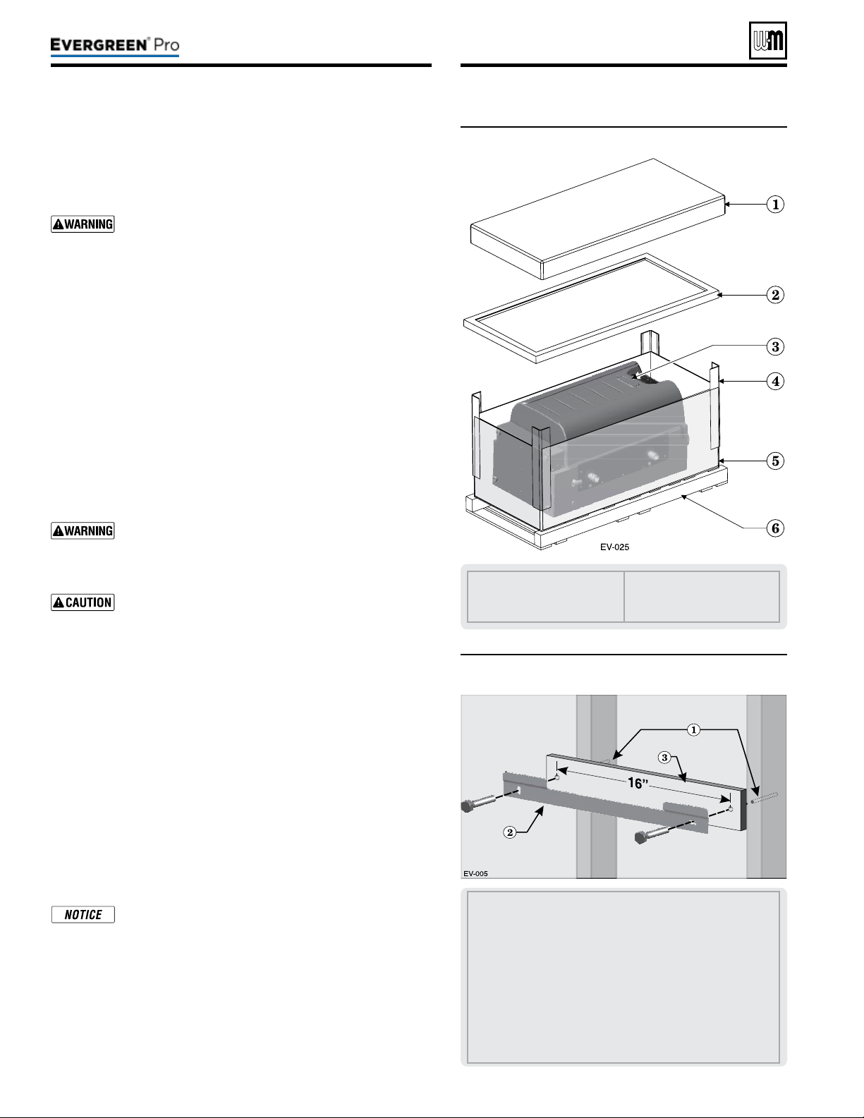
2. Remove items1, 2, 4, and 5 in Figure3. Remove trim kit and
parts from item6.
3. Aer removing outer shipping carton from boiler, REMOVE
jacket front door by opening door latches. Removing the door
will prevent possible damage to the door during handling.
4. Remove the additional trim kits from inside the boiler.
5. To remove boiler from pallet (aer removing jacket front door):
a. Remove the lag screws securing the shipping brackets.
b. Unscrew the two (2) rear boiler legs and remove the ship-
ping brackets and discard. e shipping brackets are NOT
to be used for wall mounting.
c. Discard the cardboard protector insert on the rear of the
boiler.
Do not drop boiler or bump jacket on oor or pallet.
Damage to boiler can result.
1. Set boiler in place, plumb and level.
a. Adjust legs, if necessary to plumb and/or level boiler.
1. Boilers can be wall mounted ONLY if using the optional wall-
mount kit available from Weil-McLain.
Figure3 Boiler shipping container
1 Studs — Pre-drill through the wall into the studs ¼ inch
diameter x 3 inches deep for 3/8-inch lag screws— Studs must
be on 16-inch centers. If studs are any other spacing, provide
a secure, solid mounting surface on which to attach the boiler
wall-mounting bracket.
2 Wall-mount bracket.
3 Provide a spacer board pre-drilled with two clearance holes,
spaced on 16 inch centers. Board must be minimum ½ inch
thick by 3½” high by 18 inches long. Clearance holes (2) should
be ½” diameter for 3/8-inch lag bolts or ¼” diameter for 3/16-
inch toggle bolts.
RECOMMENDED for drywall or plaster lathe.
Figure4 Wall-mount bracket and spacer board
Part number 550-100-211/0122
– 8 –
1 Cardboard cap, top
2 Cardboard support
3 Boiler
4 Cardboard corners
5 Cardboard outside sleeve
6 Pallet
220 /29 9/3 00 /39 9
(continued)
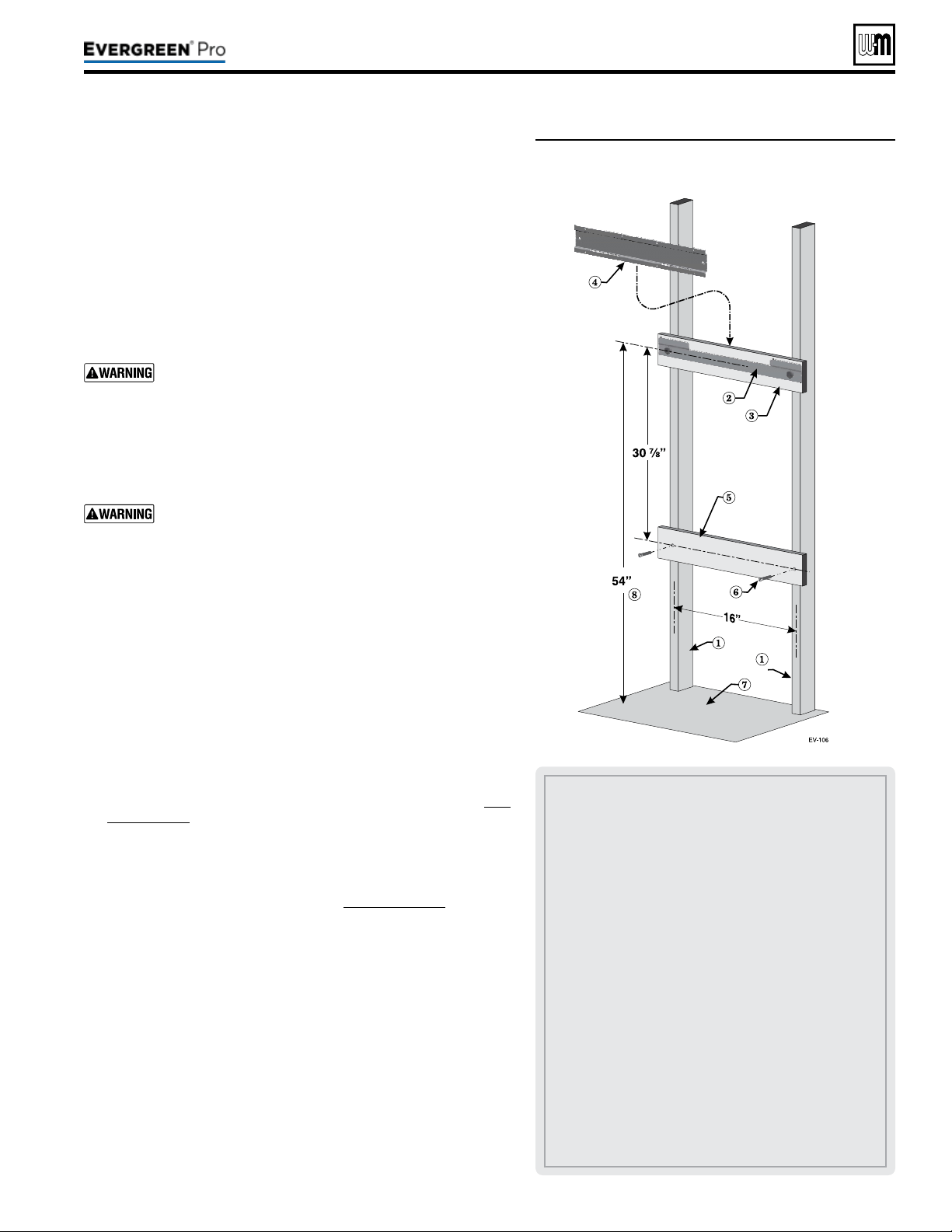
Figure5 Place boiler on wall-mount bracket
e wall-mounting kit is NOT supplied with the boiler, and must be
purchased separately.
2. Verify kit contents:
a. Wall-mount bracket
b. Lag screws, 3/8”hex head x 3” (2)
3. Verify mounting location:
a. Wood stud wall: install bracket with lag screws included in
kit, directly into the studs.
b. Metal stud wall: secure bracket to studs with 3/16” toggle
bolts and at washers (not included with kit).
Verify that the studs are suitable for carrying a wall-
mounted load. Some metal studs are not designed for
this purpose.
1. Locate studs. Bracket holes are spaced for 16” center studs. For
other stud spacing, provide secure, solid mounting structure on
which to attach the wall-mounting bracket.
DO NOT attempt to attach the wall mount bracket using
anchors or any means other than directly securing to the
wall studs (or equivalent wood structure if studs are not
on 16-inch centers).
Theboilermustbeverticallyplumbandcapableof
carryingtheweightoftheboilerandanyattached
components
.
e operating weights for Evergreen
®
models are:
Evergreen 220: 190pounds
Evergreen 299/300: 255pounds
Evergreen 399: 255pounds
Failure to comply with above and the procedure given
below could result in severe personal injury, death or
substantial property damage.
2. Optional – If boiler is being mounted on drywall or similar
surface, provide spacer boards to be installed as shown in Fig-
ure4,page8 and Figure5. e boards must be a minimum of
½” thick. Prepare upper board by tracing the mounting slots
on the board, and drilling two ¼” through holes in the center of
the outlines. Skip to step 5.
3. Place the wall-mount bracket on the wall so that the mounting
slots are centered over the studs (see Figure4,page8). If using
a backing board, skip this step.
4. Level the bracket using a level and trace the outline of the screw
slots with a pencil. If using a backing board, skip this step.
5. Remove the wall-mounting bracket and drill ¼” diameter by 3”
deep holes, centered in the bracket slot outlines. For metal stud
walls using 3/16” toggle bolts, drill required clearance holes. If
using a backing board, use the upper board as a template to drill
two (2) ¼” by 3” deep holes into the wall studs.
6. Position the bracket (and upper spacer board, if used) on the
wall. Insert and loosely tighten the two (2) lag screws (or toggle
bolts for metal studs).
7. Level the wall-mounting bracket, and tighten lag screws so
bracket is secured. For installations using a backing board, avoid
over-tightening the screws to avoid damage to the wall surface.
1 Studs — Pre-drill through the wall into the studs ¼ inch
diameter x 3 inches deep — Studs must be on 16-inch centers.
If studs are any other spacing, provide a secure, solid mounting
surface on which to attach the boiler wall-mounting bracket.
2 Wall-mount bracket — secure wall mount bracket and space
bar to wall as instructed on previous page.
3 Upper spacer board — (Recommended for drywall or plaster
lathe)
4 Boiler mounting bracket — e two slots in the bracket on
back of boiler must engage with the two tabs on the wall
bracket. is piece is attached to the boiler. (e boiler is not
shown to improve clarity.)
5 Lower space board — Provide lower spacer board pre-drilled
with two clearance holes, spaced on 16 inch centers. Board
must be minimum ½ inch thick by 3½” high by 18 inches
long. Use minimum two at-head wood screws by 2inches
long to secure the space board securely to the studs. Clearance
holes should large enough to clear the sha of the at-head
wood screws used to secure the board to the studs.
(RECOMMENDED
for drywall or plaster lathe).
6 Flat-head wood screws by 2” long.
7 Floor surface.
8 RECOMMENDED mounting height — for garage installa-
tions.
Part number 550-100-211/0122
– 9 –
220 /29 9/3 00 /39 9

DONOTinstallareliefvalvewithapressurehigher
than80PSIG
. is is the maximum allowable relief valve
setting for the Evergreen
®
boiler. Failure to comply could
prevent the relief valve from operating as needed, resulting
in possibility of severe personal injury, death or substantial
property damage.
Usetwowrencheswhentighteninganypipeconnec-
tiontotheboiler
. Failure to prevent the boiler pipes from
turning could damage pipes, resulting in possible severe
personal injury, death or substantial property damage.
Pressure test the boiler before permanently attaching water or gas piping
or electrical supply.
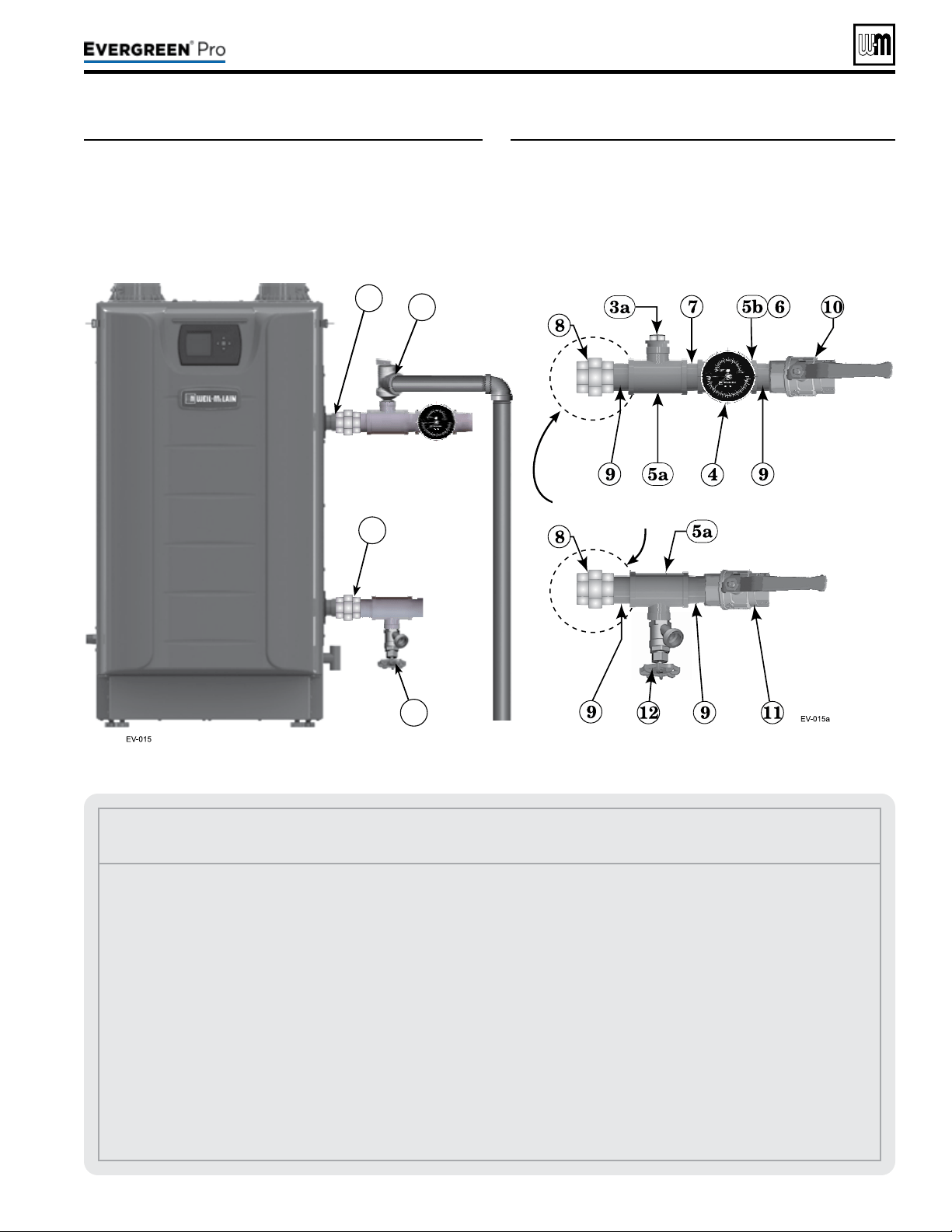
1. Install the (Item 5a) two 1½” reducing tee (EVG 220 model) or two
1½” tees (EVG 299/300 & 399 models), and close nipple shipped
loose with the boiler, located and oriented as shown in Fig-
ure6,page11 and Figure7,page11, on the boiler supply and return.
2. Install the (Item 5b) one 1¼” NPT tee on EVG 220 or 1½” NPT tee on
EVG 299/300/399) and close nipples shipped loose with the boiler,
located and oriented as shown in Figure6,page11 on the boiler supply.
DONOTinstallthereliefvalveuntilafterthehydrostatic
test
. Temporarily install a ¾” pipe plug in the relief valve
location as directed in these instructions. e plug must be
removed aer the test.
3. Apply pipe dope to all ttings sparingly.
-
1. e following piping components (supplied by installer) are required
for the test conguration:
a. Two isolation shut-o valves (1¼” NPT on EVG 220; 1½” NPT on
EVG 299/300/399).
b. 1¼” NPT or 1½” NPT pipe nipples as shown in Figure7,page11.
c. ¾” NPT pipe plug.
2.
TEMPORARILY insert a ¾” NPT pipe plug in the relief valve tapping.
Aer the hydrostatic test, this plug must be removed and the relief
valve must be installed.
3. Install Pressure/Temperature gauge into the tee (Item 5b) as shown in
Figure7,page11.
1. See Figure6,page11 for use with the following instructions.
2. CLOSE boiler drain valve (item12). Connect a hose to fresh water
supply and to the drain valve.
3. Place a bucket under the ends of Isolation shut-o valves (item10 and
item11) to catch water drippage.
4. CLOSE isolation valve 11. (Return)
5. OPEN top isolation valve 10. (Supply)
6. Slowly open boiler drain valve (item12) and fresh water supply to ll
boiler with water. e boiler and internal piping will ll quickly because
of the low water content.
8. If upper spacer board is used, install the lower
spacer board as shown in Figure5,page9.
9. Once the wall-mount bracket is installed,
measure 35” below the bottom edge of the
bracket and strike a line or place a piece of
masking tape with the top edge even with the 35”
mark. is line will indicate if the boiler has been
properly seated in the hanging bracket.
10. Obtainassistancetolifttheboilerinto
position.
Theboilerisheavy, and requires
two people to li and place. Wear
non-slip rubber gloves to prevent pos-
sibility of cuts from sheet metal edges.
e jacket door can be le on boiler,
but boiler must ONLY be lied from
the bottom and rear of the sheet metal
housing, NOT from the pipes or any
plastic part.
11. Li the boiler high enough that its rear bracket
(item4, Figure5,page9) will be above the wall-
mount bracket.
12. Slide the boiler down so that the back of the cabi-
net is in contact with the lag screw heads until
t
he bottom of the boiler is below the line or tape
placed in Step 9. If necessary, move boiler le or
right until the tabs on the wall-mounting bracket
insert into the back of the cabinet.
When mounting the boiler, use the
method described in Step 9 to ensure
the cabinet is fully seated on wall
mounting bracket. If the bracket is
not fully engaged, the boiler could fall.
Failure to comply could result in severe
personal injury, death, or substantial
property damage.
(continued)
Part number 550-100-211/0122
– 10 –
220 /29 9/3 00 /39 9
Part number 550-100-211/0122
– 11 –
220 /29 9/3 00 /39 9
Figure6 Install piping ttings for relief valve and
pressure/temperature gauge –– DONOT
mountreliefvalveuntilAFTERhydrostatic
testing
(see legend below)
Figure7 Install piping components required for
hydrostatic test
(see legend below)
(continued)
Legend for Hydrostatic Testing
1 Boiler supply (outlet) connection, male 1½” NPT.
2 Boiler return connection, male 1½” NPT.
3 Boiler relief valve, shipped loose with boiler —
DONOT
mountreliefvalveuntilAFTERhydrostatictesting.
3a TEMPORARILYONLY—
Insert a ¾” NPT plug in the
relief valve tapping of the reducing tee.
ThisMUSTBEREMOVEDafterthetestandtherelief
valvemountedhere.
4
Pressure/temperature gauge, shipped loose with boiler.
5a Reducing tee, NPT, 1½” x 1¼” x ¾” on EVG 220 or 1½”x
1½”x ¾” on EVG 299/300/399, shipped loose with boiler.
5b Reducing tee, NPT 1¼” x 1¼” x ¼” on EVG 220 or 1½” x
1½” x ¾” on EVG 299/300/399, shipped loose with boiler.
6 Bushing, ¾” NPT x ¼” on EVG 299/300/399, shipped loose
with boiler.
7 Nipple, 1¼” NPT x close or 1½” NPT x close, shipped loose
with boiler.
8 Unions, 1 ½” NPT by installer (recommended, but NOT
furnished).
9 Pipe nipple, 1¼” NPT x close or 1½” NPT x close, by in-
staller.
10 Isolation valve on supply connection, by installer (1¼”NPT
on EVG 220, 1 ½” NPT on EVG 299/300/399).
11 Isolation valve on return connection, by installer (1¼”NPT
on EVG 220, 1½” NPT on EVG 299/300/399).
12 ¾” NPT boiler drain valve, shipped loose with boiler — aer
hydrostatic testing, move drain valve to lowest point on the
return piping.
Piping to system
12
2
1
3
Piping from
system
Recommended but
not included
7. When water begins to exit from the supply outlet,
close the boiler drain valve (item12).
8. OPEN isolation valve 11. Close this valve when
water begins to run from the return isolation shut-
o valve (item11).
9. Continue lling by opening the boiler drain valve
(item 12) until water flows from supply outlet
isolation shut-o valve (item10). en CLOSE
isolation valve 10.
10. e test pressure should be 1-½ times the pressure
setting of the relief valve to be installed on the
boiler (45psig for a 30-psig relief valve; 75psig
for a 50-psig relief valve; or 120 psig for a 80-psig
relief valve). Open boiler drain valve until desired
pressure is achieved.
11. Hold at test pressure for 10 minutes.
Do not leave boiler unattended. A cold
water ll could expand and cause exces-
sive pressure, resulting in severe per-
sonal injury, death or substantial property
damage.
12. Make sure constant gauge pressure has been main-
tained throughout test. Check for leaks. Repair if
found.
Do not use petroleum-based cleaning
or sealing compounds in boiler system.
Gaskets and seals in the system may be
damaged. is can result in substantial
property damage.
1. Disconnect ll water hose from water source.
2. Drain boiler through drain valve.
Use caution when releasing pressure from
the boiler. Rapid water ow could cause
injury.
3. Remove hose aer draining.
4. Remove nipples and valves unless they will remain
for use in the system piping.
5. Remove plug and install relief valve as specied in
the following WARNING.
Remove plug from relief valve tee. Install
the relief valve in the ¾” tee, see page41
to install relief valve discharge piping.
Failure to install the boiler relief valve
could result in severe personal injury,
death or substantial property damage.
Figure8 Natural and Liqueed Petroleum (Propane) gas
conversion kits
Leaksmustberepairedatonce. Fail-
ure to do so can damage boiler, resulting
in substantial property damage.
Part number 550-100-211/0122
– 12 –
(continued)
Evergreen
®
ALL Evergreen
®
boilersmustbeconverted
forpropaneoperation
.
Convertinganexistingnaturalgas-redboilerfor
propane
— For a boiler already installed, you must
turn o gas supply, turn o power and allow boiler
to cool before proceeding. You must also completely
test the boiler aer conversion to adjust gas valve to
proper setting, verify performance, and start up the
boiler following instructions beginning on page86 of
this manual.
Verifypropanegasventuri— See Figure9,page13
LP gas venturi will have a black label and will be clearly
labeled “LP”.
Must change control settings to proper gas type.
Failure to comply could result in severe personal injury,
death or substantial property damage.
is conversion kit shall be installed by a qualied
service agency in accordance with the manufacturer’s
instructions and all applicable codes and requirements
of the authority having jurisdiction. If the information
in these instructions is not followed exactly, a re, an
explosion or production of carbon monoxide may result
causing property damage, personal injury or loss of life.
e qualied service agency is responsible for the proper
installation of this kit. e installation is not proper and
complete until the operation of the converted appliance is
checked as specied in the manufacturer’s instructions.
Natural Gas to Liqueed Petroleum (Propane)
conversion kits
EVG220LPP/N 540-202-849 NG to Propane Gas Conversion Kit contents:
511-050-236 Venturi - Liqueed Petroleum (Propane) Gas 1
562-150-292 Screw Pan Hd T20 M4x12 w/Square Cone Lock Washer 3
562-248-765 Washer .89 ID x 1.19 OD Garlock 1
590-318-102 O-Ring 3mm x 70mm Black 1
590-318-103 Gasket 1-Lips EPDM Ring 60 Dia MM 1
550-225-336 Label Gas Conversion 1
550-143-004 Instructions Conversion Nat to LP Gas 1
220 /29 9/3 00 /39 9
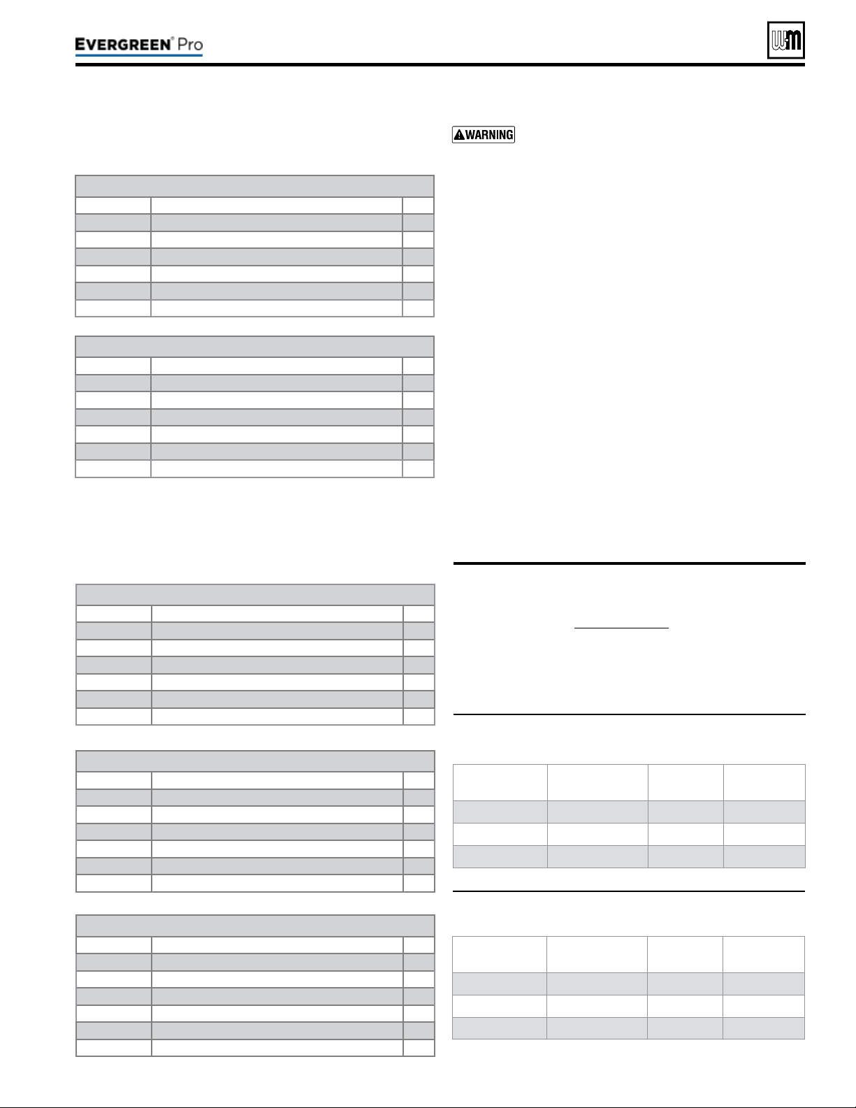
Figure9 Propane gas venturi label identication
(Black label)
Figure10 Natural gas venturi label identication
(White label)
Part number 550-100-211/0122
– 13 –
220 /29 9/3 00 /39 9
1. Propane venturi will have a black label identifying venturi
part number. See Figure8,page12 for correct part number.
2. Verify that the label on the propane venturi is correct for the
model size (see Figure9 below).
3. If the jacket front door was not already removed, remove it.
Boiler
Model
PartNumber GasType VenturiØ
EVG 220
511-050-236 LPG 30
EVG 299/300 511-050-220 LPG 34
EVG 399 511-050-221 LPG 38
y Follow all instructions in proper order.
y Do not tamper with venturi. DO NOT change or modify
venturi in any way.
y Dispose of an uninstalled venturi; do not leave in the building.
y Caution – the gas supply shall be shut o prior to discon-
necting the electrical power, before proceeding with the
conversion.
y Whenever the venturi is removed, all gaskets must be replaced
with new gaskets.
(continued)
Pipesizingforpropanegas
1. Contact gas supplier to size pipes, tanks and 100% lockup
gas pressure regulator.
NaturalandPropanesupplypressure
1. Adjust propane supply regulator provided by gas supplier
between the pressure listed below:
2. Pressure required at gas valve inlet pressure port:
a. Maximum: 14” (356 mm) w.c. with no ow (lockup).
b. Minimum gas pressure, with gas owing (verify during
boiler startup, while boiler is at high re): 3½” (89mm) w.c.
Boiler
Model
PartNumber GasType VenturiØ
EVG 220
511-050-212 NG 30
EVG 299/300 511-050-215 NG 34
EVG 399 511-050-216 NG 38
EVG299/300LPP/N 540-202-841 NG to Propane Gas Conversion Kit contents:
511-050-220 Venturi - Liqueed Petroleum (Propane) Gas 1
562-150-292 Screw Pan Hd T20 M4x12 w/Square Cone Lock Washer 3
562-248-765 Washer .89 ID x 1.19 OD Garlock 1
590-318-102 O-Ring 3mm x 70mm Black 1
590-318-103 Gasket 1-Lips EPDM Ring 60 Dia MM 1
550-225-336 Label Gas Conversion 1
550-142-871 Instructions Conversion Nat to LP Gas 1
EVG399LPP/N 540-202-842 NG to Propane Gas Conversion Kit contents:
511-050-221 Venturi - Liqueed Petroleum (Propane) Gas 1
562-150-292 Screw Pan Hd T20 M4x12 w/Square Cone Lock Washer 3
562-248-765 Washer .89 ID x 1.19 OD Garlock 1
590-318-102 O-Ring 3mm x 70mm Black 1
590-318-103 Gasket 1-Lips EPDM Ring 60 Dia MM 1
550-225-336 Label Gas Conversion 1
550-142-871 Instructions Conversion Nat to LP Gas 1
Liqueed Petroleum (Propane) to Natural Gas
conversion kits
Natural Gas to Liqueed Petroleum (Propane)
conversion kits (continued)
EVG220NGP/N 383-900-054 LP to Natural Gas Conversion Kit contents:
511-050-212 Venturi - Natural Gas 1
562-150-292 Screw Pan Hd T20 M4x12 w/Square Cone Lock Washer 3
562-248-765 Washer .89 ID x 1.19 OD Garlock 1
590-318-102 O-Ring 3mm x 70mm Black 1
590-318-103 Gasket 1-Lips EPDM Ring 60 Dia MM 1
550-225-336 Label Gas Conversion 1
550-142-160 Instructions Conversion LP to Natural Gas 1
EVG299/300NGP/N 383-900-055 LP to Natural Gas Conversion Kit contents:
511-050-215 Venturi - Natural Gas 1
562-150-292 Screw Pan Hd T20 M4x12 w/Square Cone Lock Washer 3
562-248-765 Washer .89 ID x 1.19 OD Garlock 1
590-318-102 O-Ring 3mm x 70mm Black 1
590-318-103 Gasket 1-Lips EPDM Ring 60 Dia MM 1
550-225-336 Label Gas Conversion 1
550-142-160 Instructions Conversion LP to Natural Gas 1
EVG399NGP/N 383-900-056 LP to Natural Gas Conversion Kit contents:
511-050-216 Venturi - Natural Gas 1
562-150-292 Screw Pan Hd T20 M4x12 w/Square Cone Lock Washer 3
562-248-765 Washer .89 ID x 1.19 OD Garlock 1
590-318-102 O-Ring 3mm x 70mm Black 1
590-318-103 Gasket 1-Lips EPDM Ring 60 Dia MM 1
550-225-336 Label Gas Conversion 1
550-142-160 Instructions Conversion LP to Natural Gas 1
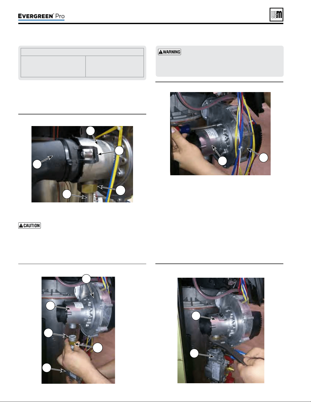
Figure11
Air silencer removal
Figure13 Removal of Natural gas venturi
Figure14 Installing the new propane gas venturi
Part number 550-100-211/0122
– 14 –
Figure12
Gas pipe loosened for propane conversion
4. Locate the blower and venturi (see Figure11).
5. Gently pull on both silencer retaining clips (Figure11, item
2) and remove air silencer from front of venturi (item 3).
Label all wires prior to disconnection when
servicing controls. Wiring errors can cause im-
proper and dangerous operation.
6. Disconnect wire harness from gas valve.
7. Loosen swivel nut (Figure11, item 7) on venturi-gas valve
connection (item 6). See Figure12. Gently set gas valve a side.
LEGENDfor Figures 11, 12, 13 and 14
1 Air Silencer
2 Air silencer clips (2)
3 Venturi
4 Blower
5 Gas valve
6 Gas pipe
7 Swivel nut
8 Fiber Washer
8. Remove three (3) T20 Torx screws holding the venturi,
(Item 3) in place. Remove venturi, o-ring, and inspect
blower surface. Discard old o-ring and ber washer, see
Figure13.
9. Install new propane venturi and o-ring from conversion kit.
10. Ensure o-ring is seated properly in groove on blower.
11. Insert three (3) new Torx screws from conversion kit to
hold venturi in place. Torque screws to no more than 23
inch-pounds.
12. Reassemble gas pipe with new ber washer from conversion
kit to the venturi connection, using two wrenches to tighten
swivel nut. Replace silencer gasket and re-attach air silencer
to venturi. See Figure14.
(continued)
Usetwowrenches when tightening gas piping at
boiler, using one wrench to prevent the boiler gas
line connection from turning. Failure to support
the boiler gas connection pipe to prevent it from
turning could damage gas line components.
220 /29 9/3 00 /39 9
4
8
3
7
5
5
3
1
7
2
6
3
4
3
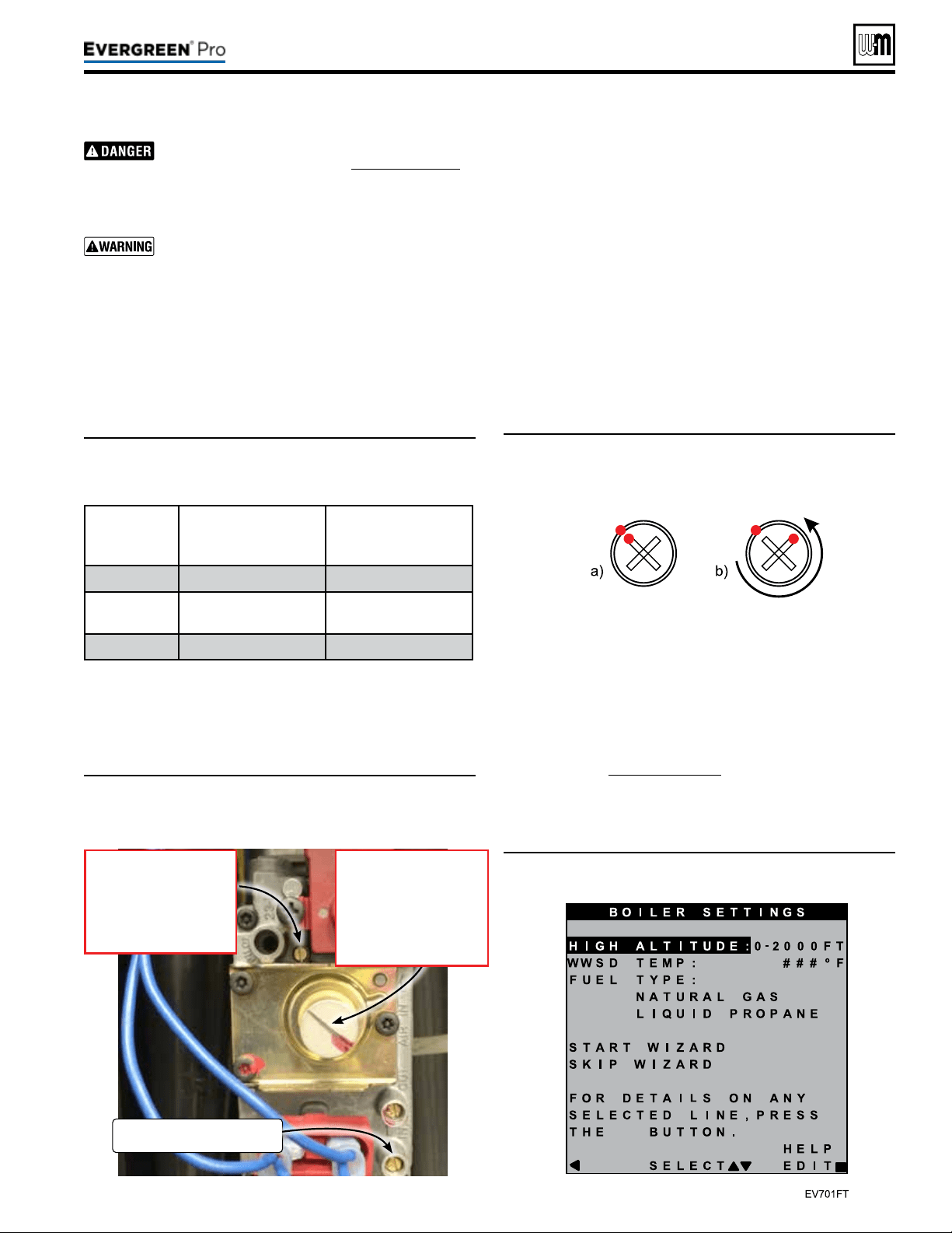
Figure15 Gas valve adjustment locations—ONLY for use
by a qualied technician, using properly working,
calibrated combustion test instruments.
Figure16 Offset regulating screw adjustment—(a)
Marking factory-provided NG position. (b) View
after 3/4 turn CCW adjustment.
Figure17 Evergreen
®
fuel type setting screen
Part number 550-100-211/0122
– 15 –
220 /29 9/3 00 /39 9
Inspect the gas pipe tting connections on the gas
valve and new venturi (Item3, Figure14,page14).
Check the seal of the connections. Failure to
comply will cause a gas leak, resulting in severe
personal injury or death.
Do not check for gas leaks with an open ame —
use bubble test. Failure to use bubble test or check
for gas leaks can cause severe personal injury,
death or substantial property damage.
13. Prior to the boiler’s rst ignition, adjust the throttle adjust-
ment screw by rst turning the screw clockwise (P) until it
bottoms out – do not apply any additional or excess torque.
Adjust the throttle screw in a counterclockwise (Q) direc-
tion with precisely the number of turns listed in Table 1,
according to the boiler model/size.
(continued)
Table1: Course adjustment settings—Throttle and offset
adjustments to be made prior to rst ignition, by
size.
Boiler
Model
ThrottleTurns
(Counterclockwise Q from
Bottom-out Position)
OffsetTurns
(Counterclockwise Q
Factory NG Position )
EVG 220LP
5/8 3/4
EVG
299/300LP
1-3/8 1/4
EVG 399LP
1-5/8 1/4
14. Aer the throttle has been adjusted coarsely, the oset regulat-
ing screw must be adjusted. Remove the sealed, slotted cap
protecting the white oset regulating screw before making
adjustments. It is critical to be precise for the adjustment of
the oset regulating screw. DO NOT attempt to bottom out
the oset regulating screw as was done for the throttle adjust-
ment. Adjustments to the oset regulating screw should be
made from the factory-provided natural gas position.
Adjust the oset regulating screw using the follow-
ing steps, referencing Figure16
:
1a. Use a marker to mark the corner of one tip of the cross on
the oset regulating screw and the corresponding location
on the outside of the screw housing, as shown in Figure16a.
2b. Adjust the oset regulating screw in a counterclockwise (Q)
direction with precisely the number of turns listed in Table
1, according to the boiler model/size.
15. Reconnect wire harness to gas valve.
16. Restore electrical power, turn on gas by opening manual gas
valve and check for leaks.
17. When boiler has not been red, follow instructions on the
initial screens to select propane as the gas type. If natural
gas was already selected in the boiler control, the gas type
parameter will need to be adjusted. In the contractor menu,
under the Boiler Settings menu, adjust the “LP Gas” setting
to “YES”, see Figure75,page76.
18. Before ring, verify that the Boiler Settings are for LP gas,
“Max Rate” for the input (priority) used to re the boiler
GasInletPressure
TestPort
OffsetRegulatingscrew
• Turn clockwise
to increase CO
2
. P
• Turn counter-clockwise to
decrease CO
2
. Q
Note: Must remove cover.
Throttle adjustmentscrew
• Turn counter-clockwise
to increase CO
2
. Q
• Turn clockwise to
decrease CO
2
. P
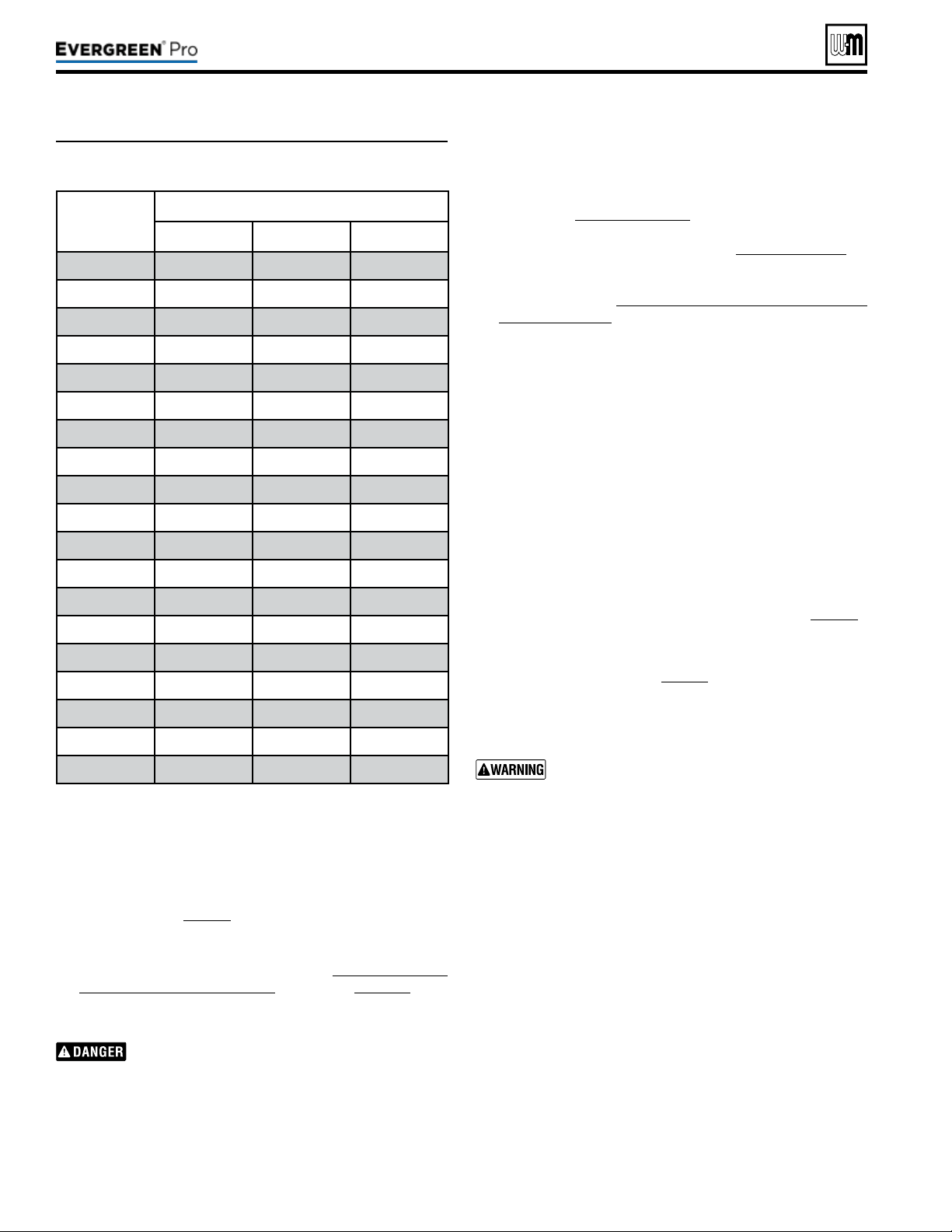
Part number 550-100-211/0122
– 16 –
Table2: Low-re blower speeds—Minimum blower speed
settings according to altitude settings.
(continued)
220 /29 9/3 00 /39 9
is set between 96% and 100%. Also verify that the ‘Min
Rate” is set to 10% or the minimum rate allowed (if above
2000 . elevation). Adjust control settings if not at proper
rate. Verify that boiler is operating at the expected ring
rate at both high- and low-re during combustion analysis.
Refer to Table 2, page16 for proper low-re rate based on
altitude settings.
19. Prior to turning on the boiler, review the procedure and
control sequence for the operation of the Manual Test Mode
for Single and Multiple Boilers starting on page101. e
procedure diers between boilers set as a single or multiple-
boiler unit.
e use of a ue gas analyzer is required to convert
this unit and determine proper gas valve settings.
Do not perform this conversion without a ue gas
analyzer. Improper gas valve settings can cause
severe personal injury, death, or property damage.
20. Do NOT allow the boiler to modulate freely until the com-
bustion analysis and adjustment is complete. Turn on and
Altitude
Setting
(ft.)
LowestRateforAltitude
220 299/300 399
0-2000 10% 10% 10%
2500 11% 11% 12%
3000 11% 11% 12%
3500 12% 11% 12%
4000 12% 12% 13%
4500 13% 12% 13%
5000 13% 12% 13%
5500 13% 13% 14%
6000 14% 13% 14%
6500 14% 13% 14%
7000 15% 14% 15%
7500 15% 14% 15%
8000 15% 14% 16%
8500 16% 14% 16%
9000 16% 15% 16%
9500 17% 15% 17%
10000 17% 15% 17%
10500 17% 16% 17%
11000 18% 16% 18%
connect properly working, calibrated combustion analyzer to
the boiler ue pipe. Fire the boiler and force it to High Fire in
Manual Test Mode. Adjust the high re combustion rst, us-
ing the throttle adjustment screw, to the CO2 and CO ranges
specied in Figure89,page91, by model size. en, force
the boiler to Low Fire and adjust the oset regulating screw
to the CO2 and CO ranges specied in Figure89,page91, by
model size. Reinstall the slotted cap over the oset adjustment
screw. Follow the full startup instructions found in this Boiler
Manual including Re-check the Maximum and Minimum
CO2 and CO rate.
21. e coarse adjustment prescribed by this manual should
result in combustion settings that allow for ignition and
are a starting point for further adjustment. If, aer making
the coarse adjustments prescribed above, the boiler will not
light, turn the throttle screw only counterclockwise (Q) an
additional 1/4 turn and attempt to light again. Repeat for a
total of up to one full turn. If, aer following the procedure
above, the boiler still will not ignite or, during combustion
analysis, the analyzer reads less than 1.0% O2, contact Weil-
McLain Technical Services for assistance.
22. Check for gas leaks and conrming proper performance.
Perform complete start-up sequence (beginning on page86),
including check for gas leaks and checking for proper operation.
Aer placing the boiler in operation, the ignition system safety
shuto device must be tested, page91.
Install front door aer servicing. e front door
must be securely fastened to the boiler frame
to prevent boiler from drawing air from inside
the boiler room. is is particularly important if
the boiler is located in the same room as other
appliances. Failure to keep the door securely fastened
could result in severe personal injury or death.
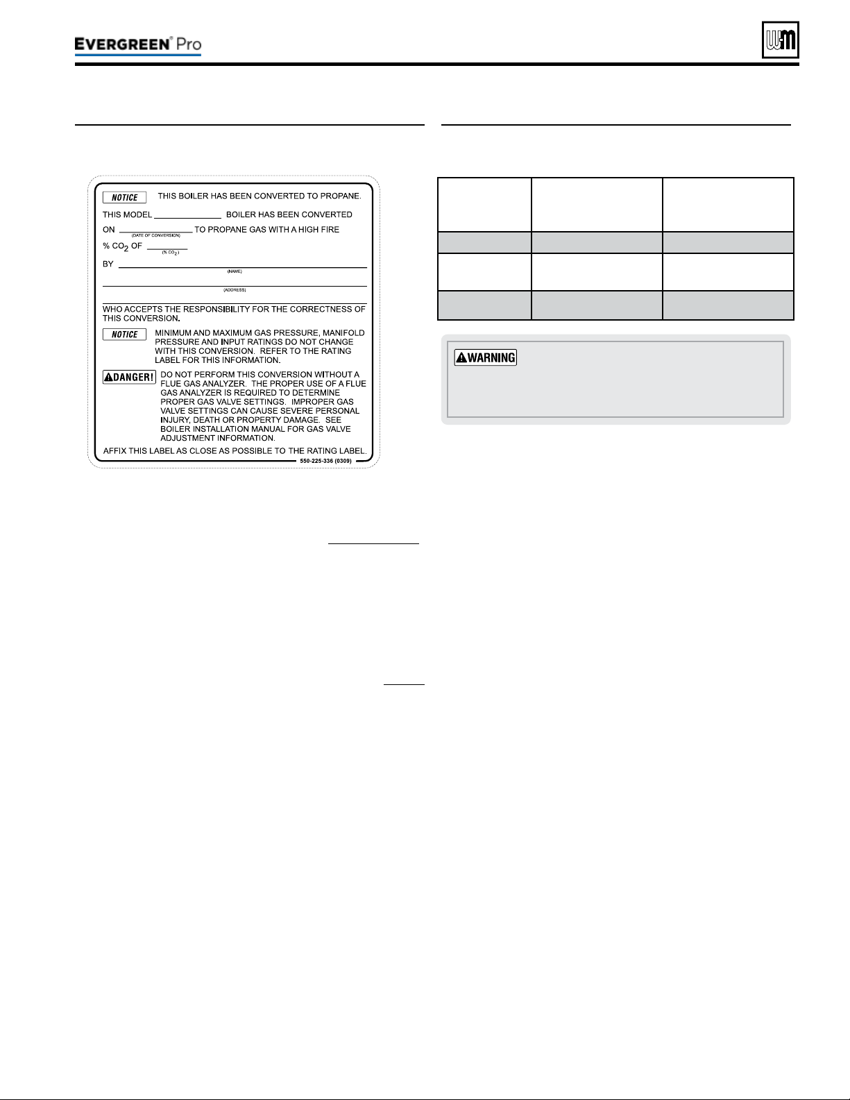
1. Aer installation is complete and boiler is set up for propane
gas, ll out and attach the propane conversion label next to
the boiler rating label (le side of cabinet).
2. Contractor/installer is responsible for completing the in-
formation required on label (provided in kit) and attaching
installer conversion label next to the boiler rating label.
Part number 550-100-211/0122
– 17 –
220 /29 9/3 00 /39 9
(continued)
1. Follow the same instructions as LP conversion, except using
the correct Natural gas conversion kit, See Figure8,page12 .
2. If LP gas was already selected in the boiler control, the gas
type parameter will need to be adjusted. In the contractor
menu, under the Boiler Settings menu, adjust the “LP Gas”
setting to “NO”.
3. Turn throttle screw clockwise until it stops, and then turn
counter-clockwise number of turns per Figure19. Figure19
is intended to make rough adjustment to gas valve to allow
the boiler to re. ey are NOT intended to replace proper
adjustment of combustion valves per instructions on page91
of this manual.
4. Adjust the oset regulating screw in a Clockwise direction
the number of turns listed in Figure19, according to the
boiler model/size.
Thedoormustbeinplaceduringopera-
tion.
DO NOT operate the boiler with the
jacket door removed except for inspection and
testing as directed in this manual.
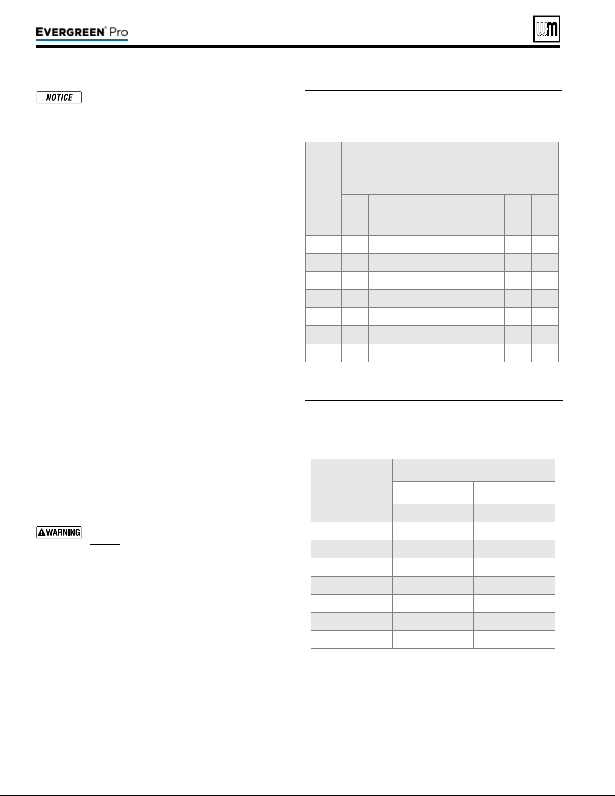
Figure19 Course adjustment settings—Throttle and
offset adjustments to be made prior to rst
ignition, by size.
Boiler
Model
ThrottleTurns
(Counterclockwise Q from
Bottom-out Position)
OffsetTurns
(Clockwise P
Factory LP Position )
EVG 220NG
1-5/8 3/8
EVG 299/300
NG
3-3/4 1/8
EVG 399NG
3 1/8
Figure18 Installer conversion label
Part number 550-100-211/0122
– 18 –
Pipesize
inches
Equivalentlength,feet
90°Elbow
Tee
¾ 2.06
4.12
1 2.62 5.24
1¼ 3.45 6.90
1½ 4.02 8.04
2 5.17 10.30
2½ 6.16 12.30
3 7.67 15.30
4 10.10 20.20
Boiler gas connection is ¾” NPT. Size gas lines
large enough to provide gas to all connected
appliances.
Pipesizingfornaturalgas
1. Size gas piping from meter outlet to entrance of boiler in
accordance with Figure20 and Figure21.
2. Use total input of all connected appliances. Divide total input
in Btuh by 1,000 to obtain cubic feet per hour of natural gas.
a. Pipe lengths in Figure20 are equivalent length of straight
pipe. Convert pipe ttings to equivalent lengths using
data from Figure21.
b. Figure20 is only for natural gas with specic gravity
0.60, with a pressure drop through the gas piping as
listed in the table.
c. For additional gas pipe sizing information, refer to ANSI
Z223.1 NFPA 54 - latest edition (or Natural Gas and
Propane Installation
CAN/CSA
B149.1 or B149.2 for
Canadian installations).
Naturalgassupplypressure
1. Pressure required at gas valve inlet pressure port:
a. Maximum: 14” (356 mm) w.c. with no ow (lockup).
b. Minimum gas pressure, with gas owing (verify dur-
ing boiler startup, while boiler is at high re):
3½” (89mm) w.c.
2. Install 100% lockup gas pressure regulator in supply line if
inlet pressure can exceed 14” w.c. at any time. Adjust lockup
regulator for 14” w.c. maximum.
You must follow the instructions, beginning on
page12, to operate the boiler on propane. Failure
to comply could result in severe personal injury,
death or substantial property damage.
Pipesizingforpropanegas
1. Contact gas supplier to size pipes, tanks and 100% lockup
gas pressure regulator.
Propanesupplypressure
1. Adjust propane supply regulator provided by gas supplier
between the pressures listed below:
2. Pressure required at gas valve inlet pressure port:
a. Maximum: 14” (356 mm) w.c. with no ow (lockup).
b. Minimum gas pressure, with gas owing (verify dur-
ing boiler startup, while boiler is at high re):
3½” (89mm) w.c.
Gas
pipe
total
length,
feet
Capacity
Cubic feet per hour, natural gas, 0.60 specic gravity
Gas pressure 14” (356 mm) w.c. or less
Pressure drop 0.3 inches (7.6 mm) w.c.
¾” 1” 1¼” 1½” 2” 2½” 3” 4”
10 278 520 1050 1600 3050 4800 8500 17500
20 190 350 730 1100 2100 3300 5900 12000
30 152 285 590 890 1650 2700 4700 9700
40 130 245 500 760 1450 2300 4100 8300
50 115 215 440 670 1270 2000 3600 7400
75 105 175 360 545 1020 1650 3000 6200
100 96 150 305 460 870 1400 2500 5100
150 90 120 250 380 710 1130 2000 4100
Figure20 Pipe capacity for 0.60 specic gravity natural
gas; pipe length is in equivalent feet (for non-
corrugated pipe)
Figure21 Equivalent lengths of straight pipe for typical
gas line ttings
220 /29 9/3 00 /39 9
Figure22 Corrosive contaminants and sources
Do not install the Evergreen
®
boiler into a common vent
with any other appliance. is will cause ue gas spillage or
appliance malfunction, resulting in possible severe personal
injury, death or substantial property damage.
Existing common vent systems may be too large for the
appliances remaining connected aer the existing boiler
is removed.
Failure to follow all instructions can result in ue gas
spillage and carbon monoxide emissions, causing severe
personal injury or death.
Use ONLY the venting materials and venting manufactur-
ers’ components and systems approved by Weil-McLain.
Follow all instructions provided by the venting component
and system manufacturer. Failure to do so can cause ue
gas spillage and carbon monoxide emissions, resulting in
severe personal injury or death.
Part number 550-100-211/0122
– 19 –
220 /29 9/3 00 /39 9
Areaslikelytohavecontaminants
Dry cleaning/laundry areas and establishments
Swimming pools
Metal fabrication plants
Beauty shops
Refrigeration repair shops
Photo processing plants
Auto body shops
Plastic manufacturing plants
Furniture renishing areas and establishments
New building construction
Remodeling areas
Garages with workshops
Buildings under construction (where air is contaminated
with particulates)
Productstoavoid
Spray cans containing chloro/uorocarbons
Permanent wave solutions
Chlorinated waxes/cleaners
Chlorine-based swimming pool chemicals
Calcium chloride used for thawing
Sodium chloride used for water softening
Refrigerant leaks
Paint or varnish removers
Hydrochloric acid/muriatic acid
Cements and glues
Antistatic fabric softeners used in clothes dryers
Chlorine-type bleaches, detergents, and cleaning
solvents found in household laundry rooms
Adhesives used to fasten building products and other
similar products
Excessive dust and dirt
Youmustpipecombustionairtothe
boilerairintake
.
Install air inlet piping for the Evergreen
®
boiler as described in this manual.
e air termination tting must be in-
stalled with the clearances and geometry
relative to the vent outlet depicted in this
manual to ensure that ue products do not
enter the air intake.
Ensure that the combustion air will
not contain any of the contaminants in
Figure22. Do not pipe combustion air near
a swimming pool, for example. Avoid areas
subject to exhaust fumes from laundry
facilities. ese areas will always contain
contaminants.
Contaminated combustion air will damage
the boiler, resulting in possible severe per-
sonal injury, death or substantial property
damage.
TheEvergreen
®
boilercannotbecommonventedwithanyother
appliance
. When an existing boiler is replaced with an Evergreen
®
boiler,
the Evergreen
®
boiler CANNOT use the existing common vent. e Ev-
ergreen
®
boiler requires its own vent and air piping, as specied in this
manual. is may cause a problem for the appliances that remain on the
original common vent, because the vent may be too large.
Perform the test sequence below for
each appliance remaining on the
original common vent system. Operate each appliance individually with
other appliances turned o. is procedure will test whether the common
vent system can properly vent each appliance.
(The following is intended to test whether the appliances remaining on an
existing vent system will operate satisfactorily.)
1. Seal any unused openings in the common venting system.
2. Visually inspect the venting system for proper size and horizontal pitch
and determine there is no blockage or restriction, leakage, corrosion or
other deciencies which could cause an unsafe condition.
3. Test vent system — Insofar as is practical, close all building doors and
windows and all doors between the space in which the appliances remain-
ing connected to the common venting system are located and other spaces
of the building. Turn on clothes dryers and any appliance not connected
to the common venting system. Turn on any exhaust fans, such as range
hoods and bathroom exhausts, so they will operate at maximum speed.
Do not operate a summer exhaust fan. Close replace dampers.
4. Place in operation the appliance being inspected. Follow the lighting
instructions. Adjust thermostat so appliance will operate continuously.
5. Test for spillage at dra hood relief opening aer 5 minutes of main
burner operation. Use the ame of a match or candle, or smoke from
a cigarette, cigar, or pipe.
6. Aer it has been determined that each appliance remaining connected
to the common venting system properly vents when tested as outlined
herein, return doors, windows, exhaust fans, replace dampers, and
any other gas-burning appliance to their previous conditions of use.
Any improper operation of common venting system should be corrected so
the installation conforms with the National Fuel Gas Code, ANSI Z223.1/
NFPA 54 — latest edition. Correct by re-sizing to approach the minimum
size as determined using the appropriate tables in Part13 of that code.
Canadian installations must comply with
Natural Gas and Propane Instal-
lation Code, CAN/CSA
B149.1 or B149.2.
(continued)
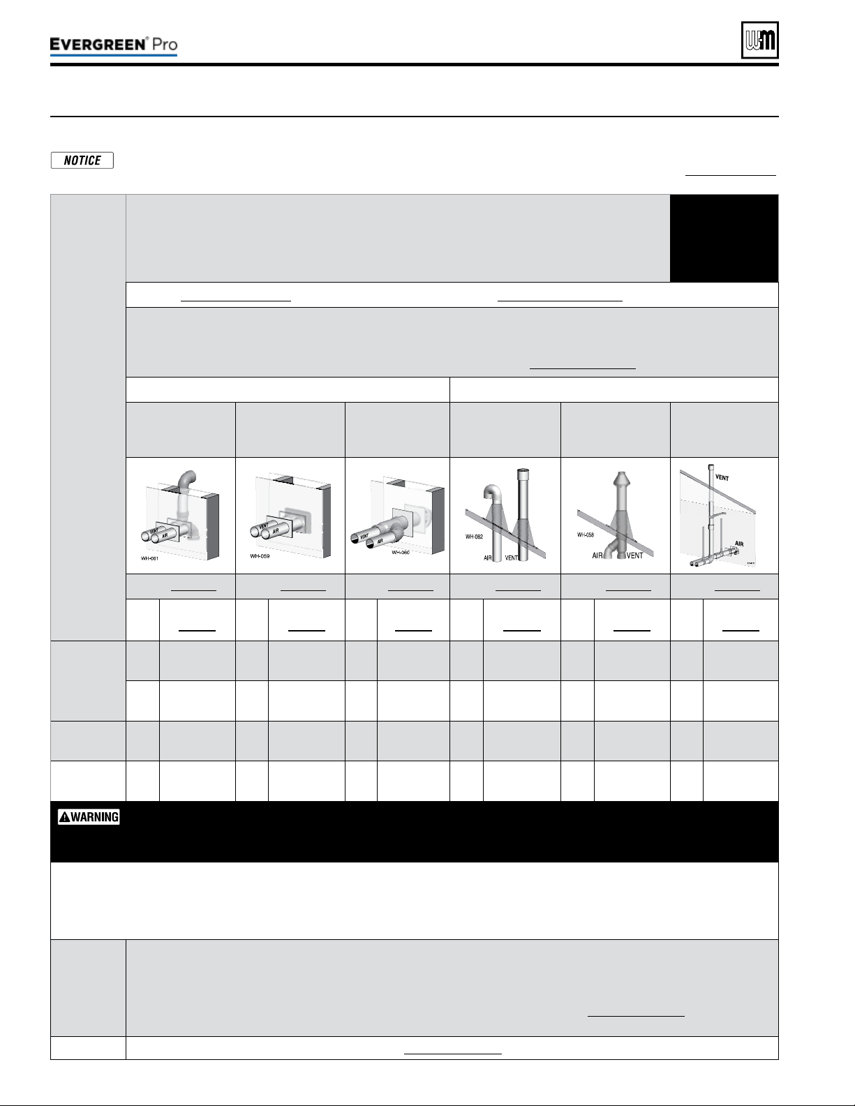
Figure23 Evergreen
®
— OPTIONS and PIPING LIMITS
e table below lists the acceptable vent/air pipe terminations described in this manual. Follow all instructions provided to install the
vent/air system. NOTSHOWN below, but also approved, are the polypropylene piping and terminations listed in Figure24,page21.
For these applications, use ONLY the manufacturers’ parts listed and follow all instructions provided by the pipe manufacturer.
Part number 550-100-211/0122
– 20 –
Evergreen
®
Model
Maximumventandairpipelength=100feetforallapplications
(Minimumlengthforallapplicationsis2feetequivalentplustermination)
(All applications include allowance for the termination ttings plus one elbow in air piping and one elbow in vent piping).
USE SWEEP
ELBOWS
ONLY
See Figure 24, page 21 for material specifications | See Figure 111, page 117 for part/kit numbers
Ventandairpipesizes:
Maximum vent lengths apply for either 3” or 4” vent and air pipe.
If using 3” pipe, provide 4”x 3” tapered reducers at boiler connections and at Weil-McLain vent/air cap or at concentric terminations.
Boilers will derate as vent/air pipe length increases — see rating data on Figure 123, page 129 for derate amounts.
SIDEWALL termination VERTICAL termination
Separate pipes
[Note 1]
Weil-McLain
vent/air plate
[Note 1 & 2]
PVC Concentric
[Note 1 & 2]
Separate pipes
[Note 1]
PVC or PP Concen-
tric
[Note 1 & 2]
Vertical vent/
Sidewall air
[Note 1]
See page 25 See page 27 See page 29 See page 31 See page 33 See page 36
Size,
inches
Materials
page 21
Size,
inches
Materials
page 21
Size,
inches
Materials
page 21
Size,
inches
Materials
page 21
Size,
inches
Materials
page 21
Size,
inches
Materials
page 21
220
3
PVC/PVC-DWV
CPVC, PP, SS
3
PVC/PVC-DWV
CPVC, PP
3
PVC/PVC-
DWV CPVC
3
PVC/PVC-DWV
CPVC, PP, SS
3
PVC/PVC-DWV
CPVC, PP
3
PVC/PVC-DWV
CPVC, PP, SS
4
PVC/PVC-DWV
CPVC, PP, SS
4
PVC/PVC-DWV
CPVC, PP
4
PVC/PVC-
DWV CPVC
4
PVC/PVC-DWV
CPVC, PP, SS
4
PVC/PVC-DWV
CPVC, PP
4
PVC/PVC-DWV
CPVC, PP, SS
299/300
4
PVC/PVC-DWV
CPVC, PP, SS
4
PVC/PVC-DWV
CPVC, PP
4
PVC/PVC-
DWV CPVC
4
PVC/PVC-DWV
CPVC, PP, SS
4
PVC/PVC-DWV
CPVC, PP
4
PVC/PVC-DWV
CPVC, PP, SS
399
4
PVC/PVC-DWV
CPVC, PP, SS
4
PVC/PVC-DWV
CPVC, PP
4
PVC/PVC-
DWV CPVC
4
PVC/PVC-DWV
CPVC, PP, SS
4
PVC/PVC-DWV
CPVC, PP
4
PVC/PVC-DWV
CPVC, PP, SS
AllelbowsinventandairpipingmustbesweepelbowsONLY.DONOTuseshort-radiuselbows.
Whentransitioningto4-inchto3-inch,usetaperedreducerwith4”PVCnipple(l
≥6”).Donotuse4-inch
to3-inchbushing.BushingwillNotsealinboileradapter.
Equivalentfeetforelbows(USESWEEPELBOWSONLY) —
deduct from max. equivalent length of piping (does not apply to termi-
nation ttings).
PVC • 7 feet per for each additional 90° sweep elbow or 45° elbow —
If piping contains more than 1 elbow in air or vent piping, other than
termination ttings.
PP • Centrotherm 3” = 6’ 4” = 20’ Duravent 3” = 17’ 4” = 22’
Note 1
Material abbreviations: PP = polypropylene, SS = AL29-4C stainless steel
If using polypropylene or stainless pipe, provide adapters for 4” boiler connections and for terminations, if required IPEX PVC
concentric vent kits can be used with standard PVC pipe, ttings and cement (ANSI/ASTM D1785) except if ULC S636 compliance is
required. For ULC S636 compliance, all pipe, ttings and cement must be IPEX System 636. For UL 1738 compliance all pipe, ttings
and cement must be IPEX System 1738. If using IPEX kits, use only IPEX product code listed in Figure111,page117.
Contact Weil-McLain for ordering information and availability of Weil-McLain venting kits.
Note 2
Use only Weil-Mclain approved termination kits listed in Figure111,page117.
220 /29 9/3 00 /39 9

(continued)
ALL vent and air pipes require a BIRD SCREEN at each termination. Most kits do not include
the bird screens. Purchase bird screens separately from Weil-McLain or vent kit supplier if
not included. [Note — bird screening is integral to the 3” and 4” PVC Weil-McLain sidewall
vent cap, purchased separately. No additional screening is required.]
Figure24 — Use only the materials listed below, ensuring that all materials meet
local codes (see Figure 111, page 117 for part/kit numbers)
Part number 550-100-211/0122
– 21 –
220 /29 9/3 00 /39 9
Item Material
Standardsforinstallationsin:
UnitedStates Canada(Note 2)
Plasticpipingmaterials Ventorairpiping Ventpiping Airpiping
Ventorairpipe
&
ttings
PVC schedule 40 (Note 1) ANSI/ASTM D1785/UL1738/ULC S636 ULC S636
PVC, PVC-DWV,
CPVC or
polypropylene
PVC-DWV schedule 40 (Note 1) ANSI/ASTM D2665 N/A
CPVC schedule 40 (Note 1) ANSI/ASTM F441 / ULC S636 ULC S636
PVC&ABSpipe
cement&primer
PVC (Note 1) ANSI/ASTM D2564 / F656 / UL1738 ULC S636
Use only cement
and primer suitable
for piping material
used
CPVC (Note 1) ANSI/ASTM F493 ULC S636
CPVC to PVC transition
Use only cement and primer suitable
for piping material used
ULC S636
Polypropylene
ventpipe,ttings,
terminationsand
cement
Simpson-Duravent—Obtain all materials from M&G
Simpson-Duravent
CentrothermEcoSystemsInnoFlue®Single-wall
—Obtain all materials from Centrotherm
(Note: See page 117 for correct appliance adapters to be used.)
See manufacturer’s literature for detailed
information
MUST USE LOCKING COLLAR
ON EVERY JOINT
ULC S636
PVC, PVC-DWV,
CPVC or
polypropylene
AL29-4Cstainlesssteelpipingmaterials
Ventpipe
AL29-4C
stainless
steel
Heat Fab, Inc. — Saf-T-Vent
®
Z-Flex, Inc. — Z-Vent
Dura-Vent — FasNSeal™
Metal-Fab, Inc. — CORR/GUARD
Certied for Category IV and direct
vent appliance venting
Certied for Category IV and direct vent
appliance venting
Weil-McLainstainlesssteelbirdscreens,3”or4”(purchase separately) — see Figure 111, page 117 for part numbers
Note 1: Weil-McLain concentric vent kits are made from PVC
pipe and ttings.
Note 2: System 636 PVC concentric terminations utilize PVC
pipe/ttings certied to ULC S636.
If ULC S636 compliance is required, use only System
636 pipe, ttings and cement.
If UL1738 compliance is required, use only System
1738 pipe, ttings and cement.
DO NOT mix piping from dierent pipe manufactur-
ers unless using adapters specically designed for the
purpose by the manufacturer.
Every joint on polypropylene vent piping must include
a locking collar.
DO NOT use cellular core PVC (ASTM F891), cellular
core CPVC, or Radel
®
(polyphenolsulfone) in venting
systems.
DO NOT cover non-metallic vent pipe and fittings
with thermal insulation.
ADAPTERS — AL29-4C piping — Install a PVC-to-stainless
adapter supplied by the AL29-4C stainless pipe manufac-
turer at the 4” PVC boiler vent connection. Can not be uesd
with Weil-McLain termination plate or concentric termina-
tion.
ADAPTERS — Polypropylene piping — Provide adapters
from polypropylene pipe to the 4” PVC connections at the
boiler and at terminations, if required (Weil-McLain side-
wall plate, for example).
ADAPTERS — If using 3” piping, where approved for the
application, provide adapters for the 4” PVC boiler con-
nections and at the terminations, if required (Weil-McLain
sidewall plate, for example).
For PVC – USE SWEEP ELBOWS FOR ALL VENT AND AIR PIPING — DO NOT use
short radius elbows for vent or air piping. Boiler performance could be affected.

Part number 550-100-211/0122
– 22 –
(a) REQUIREMENTS: For all sidewall horizontally-vented gas-
fueled equipment installed in every dwelling, building or
structure used in whole or in part for residential purposes,
including those owned or operated by the Commonwealth
and where the side wall exhaust vent termination is less than
seven(7)feet above nished grade in the area of the venting,
including but not limited to decks and porches, the following
requirements shall be satised:
1.
INSTALLATION OF CARBON MONOXIDE DETEC-
TORS
. At the time of installation of the side wall horizon-
tal vented gas fueled equipment, the installing plumber
or gas fitter shall observe that a hard wired carbon
monoxide detector with an alarm and battery back-up
is installed on the oor level where the gas equipment is
to be installed. In addition, the installing plumber or gas
tter shall observe that a battery operated or hard wired
carbon monoxide detector with an alarm is installed on
each additional level of the dwelling, building or struc-
ture served by the side wall horizontal vented gas fueled
equipment. It shall be the responsibility of the property
owner to secure the services of qualied licensed profes-
sionals for the installation of hard wired carbon monoxide
detectors.
a. In the event that the side wall horizontally vented gas
fueled equipment is installed in a crawl space or an
attic, the hard wired carbon monoxide detector with
alarm and battery back-up may be installed on the
next adjacent oor level.
b. In the event that the requirements of this subdivision
can not be met at the time of completion of installa-
tion, the owner shall have a period of thirty (30) days
to comply with the above requirements; provided,
however, that during said thirty (30) day period, a
battery operated carbon monoxide detector with an
alarm shall be installed.
2.
APPROVEDCARBONMONOXIDEDETECTORS. Each
carbon monoxide detector as required in accordance with
the above provisions shall comply with NFPA720 and be
ANSI/UL2034 listed and IAS certied.
3.
SIGNAGE. A metal or plastic identication plate shall
be permanently mounted to the exterior of the build-
ing at a minimum height of eight(8)feet above grade
directly in line with the exhaust vent terminal for the
horizontally vented gas fueled heating appliance or
equipment. e sign shall read, in print size no less than
one-half(1/2)inch in size, “GAS VENT DIRECTLY
BELOW. KEEP CLEAR OF ALL OBSTRUCTIONS.”
4.
INSPECTION. e state or local gas inspector of the
side wall horizontally vented gas fueled equipment shall
not approve the installation unless, upon inspection,
the inspector observes carbon monoxide detectors and
signage installed in accordance with the provisions of
248CMR5.08(2)(a)1 through4.
(b)
EXEMPTIONS: e following equipment is exempt from
248CMR5.08(2)(a)1 through 4:
1. e equipment listed in Chapter 10 entitled “Equipment
Not Required To Be Vented” in the most current edition
of NFPA 54 as adopted by the Board; and
2. Product Approved side wall horizontally vented gas fueled
equipment installed in a room or structure separate from
the dwelling, building or structure used in whole or in
part for residential purposes.
(c)
MANUFACTURERREQUIREMENTS—GASEQUIPMENT
VENTINGSYSTEMPROVIDED
. When the manufacturer of
Product Approved side wall horizontally vented gas equip-
ment provides a venting system design or venting system
components with the equipment, the instructions provided
by the manufacturer for installation of the equipment and
the venting system shall include:
1. Detailed instructions for the installation of the venting
system design or the venting system components; and
2. A complete parts list for the venting system design or
venting system.
(d)
MANUFACTURERREQUIREMENTS—GASEQUIPMENT
VENTINGSYSTEMNOTPROVIDED
. When the manufac-
turer of a Product Approved side wall horizontally vented gas
fueled equipment does not provide the parts for venting the
ue gases, but identies “special venting systems”, the follow-
ing requirements shall be satised by the manufacturer:
1. e referenced “special venting system” instructions shall
be included with the appliance or equipment installation
instructions; and
2. e “special venting systems” shall be Product Approved
by the Board, and the instructions for that system shall
include a parts list and detailed installation instructions.
(e)
PLASTICVENTINGSYSTEMS.
e only plastic piping which may be used for venting ap-
pliances shall be:
1. Allowed by the appliance manufacturer.
2. Listed to a national/international standard for plastic
venting systems.
3. Product-accepted for that purpose by the board.
(f)
INSTALLATIONINSTRUCTIONS. A copy of all installation
instructions for all Product Approved side wall horizontally
vented gas fueled equipment, all venting instructions, all
parts lists for venting instructions, and/or all venting design
instructions shall remain with the appliance or equipment at
the completion of the installation.
When the boiler is installed within the Commonwealth of
Massachusetts, the boiler must be installed by a licensed plumber or gas tter. Read and comply with the
instructions below.
220 /29 9/3 00 /39 9
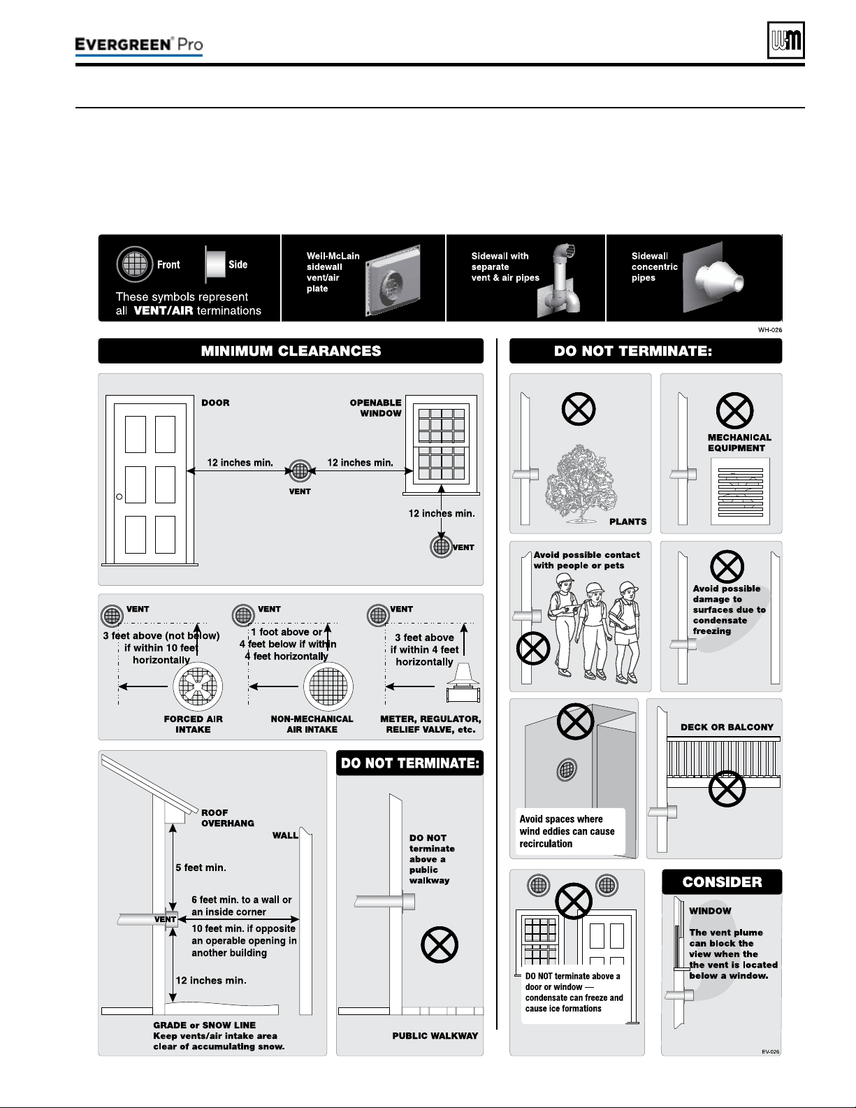
Figure25 The vent termination must be located to meet all requirements below (also applies to vertical vent terminations). The minimum
distance from adjacent public walkways, adjacent buildings, openable windows and building in the National Fuel Gas Code, ANSI
Z223.1/NFPA 54 and/or the Natural Gas and Propane Installation Code, CAN/CSA B149.1. The vent termination clearances below
are for U.S.A., for Canadian vent termination clearances please refer to the requirements of CAN/CSA B149.1 Natural Gas and
Propane Installation Code. Consideration should be given to avoid possible damage caused by vent plumes and condensate when
choosing a venting conguration and location. Maintain a minimum clearance of 4 ft. (1.22 m) horizontally from, and in no case
above or below, unless a 4 ft. (1.22m) horizontal distance is maintained, from electrical meters, gas meters, regulators, and relief
equipment.
Part number 550-100-211/0122
– 23 –
220 /29 9/3 00 /39 9
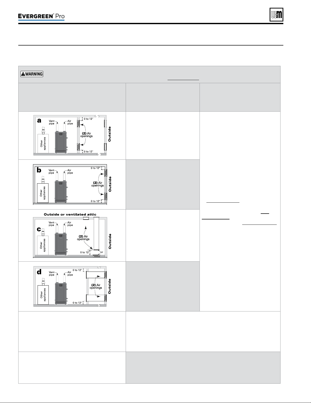
Figure26 Combustion and ventilation air openings for Evergreen
®
Direct Vent installations. Provisions for combustion
and ventilation air to be in accordance with the section “Air for Combustion and Ventilation,” of the National
Fuel Gas Code, ANSI Z223.1/NFPA 54, or applicable provisions of the local building codes.
Part number 550-100-211/0122
– 24 –
e Evergreen
®
boiler CANNOT be in the same space with other appliances if clearances around the Evergreen
®
are less than the recommended service clearances shown in Figure1,page7.
e required air opening sizes below are FREE AREA,
aer reduction for louver obstruction. Note the ex-
ception below for large spaces.
Evergre en
®
Evergre en
®
TWO openings, each at least:
1 square inch per 1,000 Btuh
of all other appliances in the room
(Unless specied otherwise by ap-
pliance manufacturer)
NO openings are required if the boiler
installation provides at least the rec-
ommended service clearances shown
in Figure 1, page 7.
If the space is smaller than Fig-
ure 1, page 7, provide openings
ONLY as shown in Figure 2, page 7.
Each opening must have a free
area no less than 1 square inch per
1,000 Btuh input of the boiler.
TWO openings, each at least:
1 square inch per 4,000 Btuh
of all other appliances in the room
— OR —
ONE opening **, each at least:
1 square inch per 3,000 Btuh
of all other appliances in the room
(Unless specied otherwise by ap-
pliance manufacturer)
TWO openings, each at least:
1 square inch per 4,000 Btuh
of all other appliances in the room
— OR —
ONE opening **, each at least:
1 square inch per 3,000 Btuh
of all other appliances in the room
(Unless specied otherwise by ap-
pliance manufacturer)
TWO openings, each at least:
1 square inch per 2,000 Btuh
of all other appliances in the room
— OR —
ONE opening **, each at least:
1 square inch per 3,000 Btuh
of all other appliances in the room
(Unless specied otherwise by ap-
pliance manufacturer)
**NOTICE:
RequirementsforusingtheSINGLEairopening
option.
A single combustion air opening can be used for cases b, c, or d above (Evergreen
®
with other appliances in room only), sized as listed, provided that:
y The single opening must communicate directly to the outdoors or to a space that
communicates directly with outdoors (NOT to an interior space).
y The top of the opening must be within 12 inches of the ceiling.
y The free area of the opening must be at least equal to the sum of the areas of all
equipment vent connectors in the space.
SPECIALEXCEPTIONFORLARGESPACES
(EvergreenWITHotherappliancesinroom
only):
NO combustion air openings are needed if the boiler (and other appliances) are installed
in a space with a volume NO LESS than 50 cubic feet per 1,000 Btuh of all appliances
in the space. That is, total the input of all appliances in MBH (1,000’s of Btuh), then
multiply this total times 50. The building MUST NOT be of tight construction.
Example: For a total input of 500 MBH (500,000 Btuh), the minimum volume would
be 50 x 500 = 25,000 cubic feet.
220 /29 9/3 00 /39 9
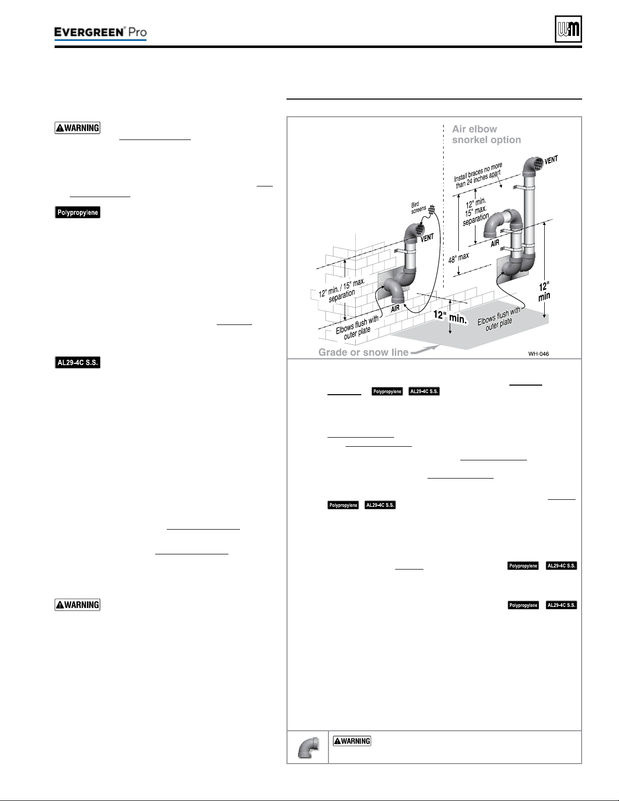
Figure27 INSTALLATIONSEQUENCE — Separate pipes sidewall
Part number 550-100-211/0122
– 25 –
220 /29 9/3 00 /39 9
DIRECT VEN T
Step1 Read and follow all instructions in this manual. DONOTproceed
withvent/airinstallationuntilyouhavereadpage19through
page24.
See notices at le.
Step2 Install the boiler in a location that allows proper routing of all vent and
air piping to the selected sidewall location.
Step3 Make sure the selected sidewall termination location complies with
Figure25,page23. (Multiple boiler sidewall plates must also comply
with Figure28,page26.)
Step4 Use only the vent materials listed in Figure24,page21. Provide pipe
adapters where required. Vent piping and air piping lengths must not
exceed the values shown in Figure23,page20.
Step5 Prepare the sidewall penetrations and secure the sidewall plates as
instructed in this section. See “Prepare wall penetrations” on page26.
See notices at le.
Step6 e air piping must terminate in a down-turnedelbow as shown
above. e vent piping must terminate in an elbowpointedoutward
orawayfromtheairinlet as shown above. See illustration above.
Step7 Install vent and air piping between the boiler and the sidewall open-
ings. Slope horizontal piping downward toward the boiler at least 1/4
inch per foot. See page38 for general guidelines.
See notices at le.
Step8 Install pipe supports every 5 feet on both the horizontal and vertical
runs. Install a hanger support within 6inches of any upturn in the pip-
ing, or per vent pipe manufacturer’s instructions.
See notices at le.
Step9 Attach the vent termination exterior piping: Use either of the congura-
tions shown above, as needed to ensure clearance above grade or snow line.
Keep vents/air intake area clear of accumulating snow.
Step10 e vent and air pipes may run up as high as 4 feet with no enclosure.
e vent and air pipes must be secured with braces, and all clearances
and lengths must be maintained. Space braces no further than 24
inches apart.
Step11 External venting greater than 4 feet requires an insulated enclosure
around the vent and air pipes. e vent and air terminations must exit
through the enclosure as shown in the illustration above, maintaining
all required clearances.
USE SWEEPELBOWS FORALL VENTAND AIR
PIPING — DO NOT use short radius elbows for vent or air
piping. Boiler performance could be aected.
Allowablevent/airpipematerials&
lengths
Use only the vent materials and kits listed
in Figure24,page21. Provide pipe adapt-
ers if specied.
1. Locate the termination such that the total air piping
and vent piping from the boiler to the termination
will not exceed the maximum length given in Fig-
ure23,page20.
For polypropylene applications, comply
with any additional requirements in the
vent system manufacturer’s instructions.
Provide 4” PVC-to-PP transition pieces
at the boiler vent and air connections. PP
adapter must have smooth, straight sec-
tion of pipe to insert in to the boiler vent
and air connections and must t and seal
tightly. PP adapters with their own seal
which would interfere with the internal
seal of the boiler vent or air connections
must not be used. Refer to page117 for a
list of compliant adapters. Install a locking
collar at every joint.
For AL29-4C vent pipe applications,
comply with any additional requirements
in the vent system manufacturer’s instruc-
tions. Provide a 4”PVC transition piece at
the boiler vent connection. e air piping
must be PVC or CPVC. Provide a 4”PVC
transition piece at the boiler air connec-
tion if using 3” air piping.
2. For 4” to 3” transitions, must use appropriate vent
material. For polypropylene or stainless steel must
use approved suppliers transitions (EVG 220 only).
Determineterminationlocation
1. Wall penetration thickness between 0” to 24”.
2. e air and vent terminations must be installed as
shown in Figure27 and Figure29,page26.
3. e terminations must comply with clearances and
limitations shown in Figure25,page23.
4. Locate the terminations so they are not likely to be
damaged by foreign objects, such as stones or balls,
or subject to buildup of leaves or sediment.
Do not exceed the maximum lengths
of the outside vent piping shown in
Figure27. Excessive length exposed to the
outside could cause freezing of condensate
in the vent pipe, resulting in potential
boiler shut down. In extremely cold cli-
mates, install an insulated chase around
the vent piping, particularly if using
longer lengths. e chase must allow for
inspection of the vent pipe, and insulation
must be protected from water.
Multiplevent/airterminations
1. When terminating multiple Evergreen
®
boilers,
terminate each vent/air connection as described in
this manual.
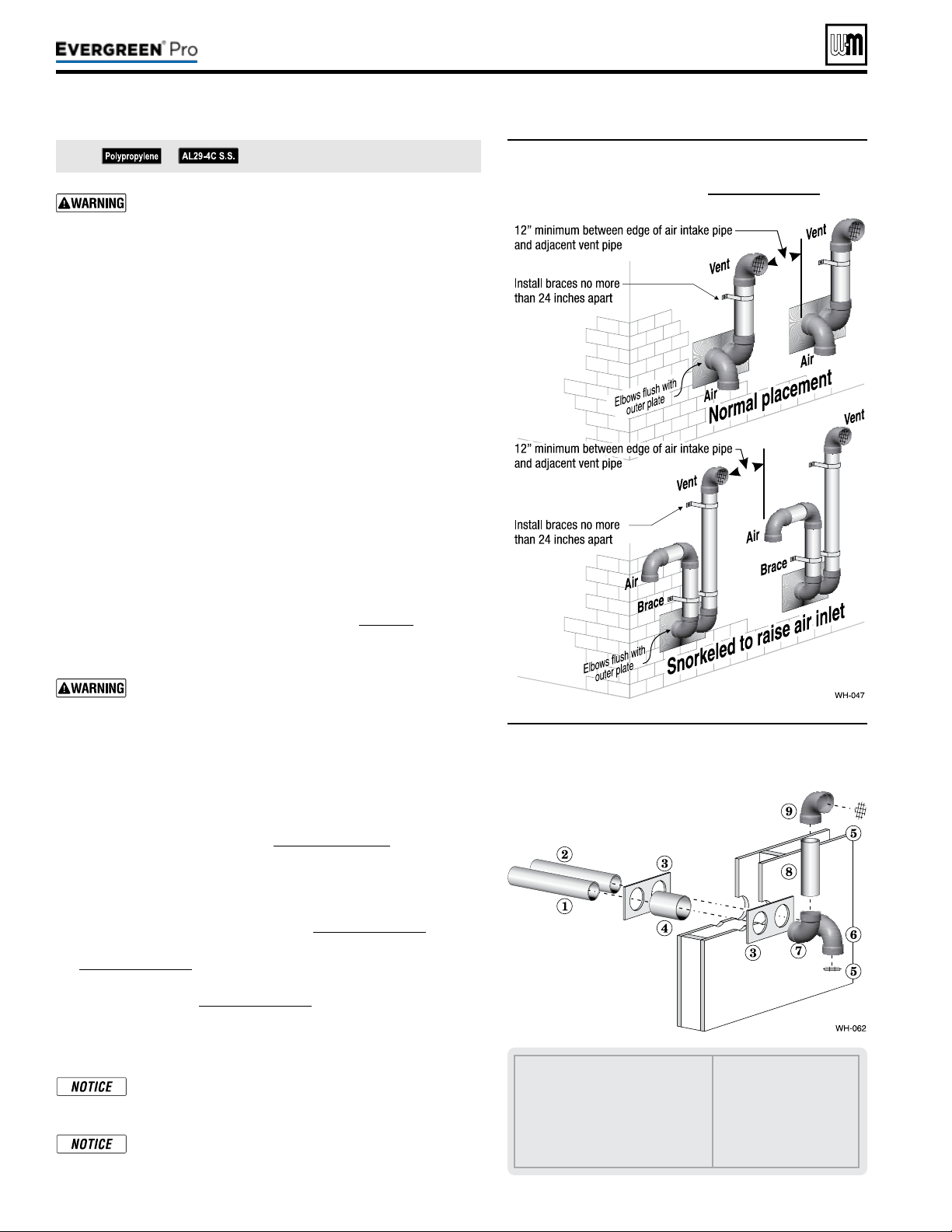
Part number 550-100-211/0122
– 26 –
DIRECT VEN T
(continued)
All vent pipes and air inlets must terminate at the same
height to avoid possibility of severe personal injury, death
or substantial property damage.
2. Place wall penetrations to obtain minimum clearances shown in
Figure28 for U. S. installations. For Canadian installations, provide
clearances required by
Natural Gas and Propane Installation Code,
CAN/CSA
B149.1 or B149.2 and a ULCS636 compliant vent kit.
3. e air inlet of a Evergreen
®
boiler is part of a direct vent connec-
tion. It is not classied as a forced air intake with regard to spacing
from adjacent boiler vents.
Preparewallpenetrations
1. Air pipe penetration:
a. Cut a hole for the air pipe. Size the air pipe hole as close as
desired to the air pipe outside diameter.
2. Vent pipe penetration:
a. Cut a hole for the vent pipe. For either combustible or non-
combustible construction, size the vent pipe hole at least 0.4”
larger than the vent pipe diameter.
b. Insert a galvanized metal thimble in the vent pipe hole as
shown in Figure29.
3. Use the provided paper template for correct location of hole centers.
4. Use of a sidewall termination plate is REQUIRED.
a. Kits for several vent sizes are available from Weil-McLain.
See “VENT/AIR PARTS AND KITS” on page117.
b. Plate may be eld fabricated from corrosion resistant material
of sucient strength. Plate must allow venting to maintain
minimum clearance to combustibles.
Ensure that the plate material is strong enough to prevent
the termination from being pushed inward if struck or
pushed from the outside.
5. Follow all local codes for isolation of vent pipe when passing
through oors or walls.
6. Seal exterior openings thoroughly with exterior caulk.
Terminationandttings
1. Prepare the vent termination elbow and the air termination elbow
by inserting bird screens. (See Figure27,page25.) Bird screens
must be purchased separately. See the parts list at the end of this
manual for part numbers.
2. When completed, the air termination coupling must be oriented
at least 12 inches below the vent termination and at least 12 inches
above grade or snow line as shown in Figure27,page25.
3. Orient the vent termination elbow directly outward as shown in
Figure27,page25.
4. Maintain the required dimensions of the nished termination
piping as shown in Figure27,page25.
5. For multiple boiler terminations, see Figure28.
6. Do not extend exposed vent pipe outside of building more than shown
in this document. Condensate could freeze and block vent pipe.
If extending the vent and air pipes out from the wall,
install a coupling on each pipe. Mount the piping with
the coupling ush with the outer plate.
Wall penetration thickness between 0” to 24”.
See notices on previous page.
1 Air piping.
2 Vent piping.
3 Sidewall termination plates: for
4”PVC, use plates supplied with
boiler in W-M vent/air plate kit; for
4” AL29-4C or 3” PVC, purchase
optional sidewall separate pipes plate
kit.
4 Galvanized thimble, by
installer.
5 Bird screen, by installer.
6 Air inlet elbow.
7 Elbow.
8 Nipple.
9 Elbow (vent termination).
Figure28
Multiple separate pipes sidewall terminations
— maintain vertical spacing between vent and
air ttings shown in Figure 27, page 25.
Figure29 Sidewall termination assembly — using
separate pipes
220 /29 9/3 00 /39 9
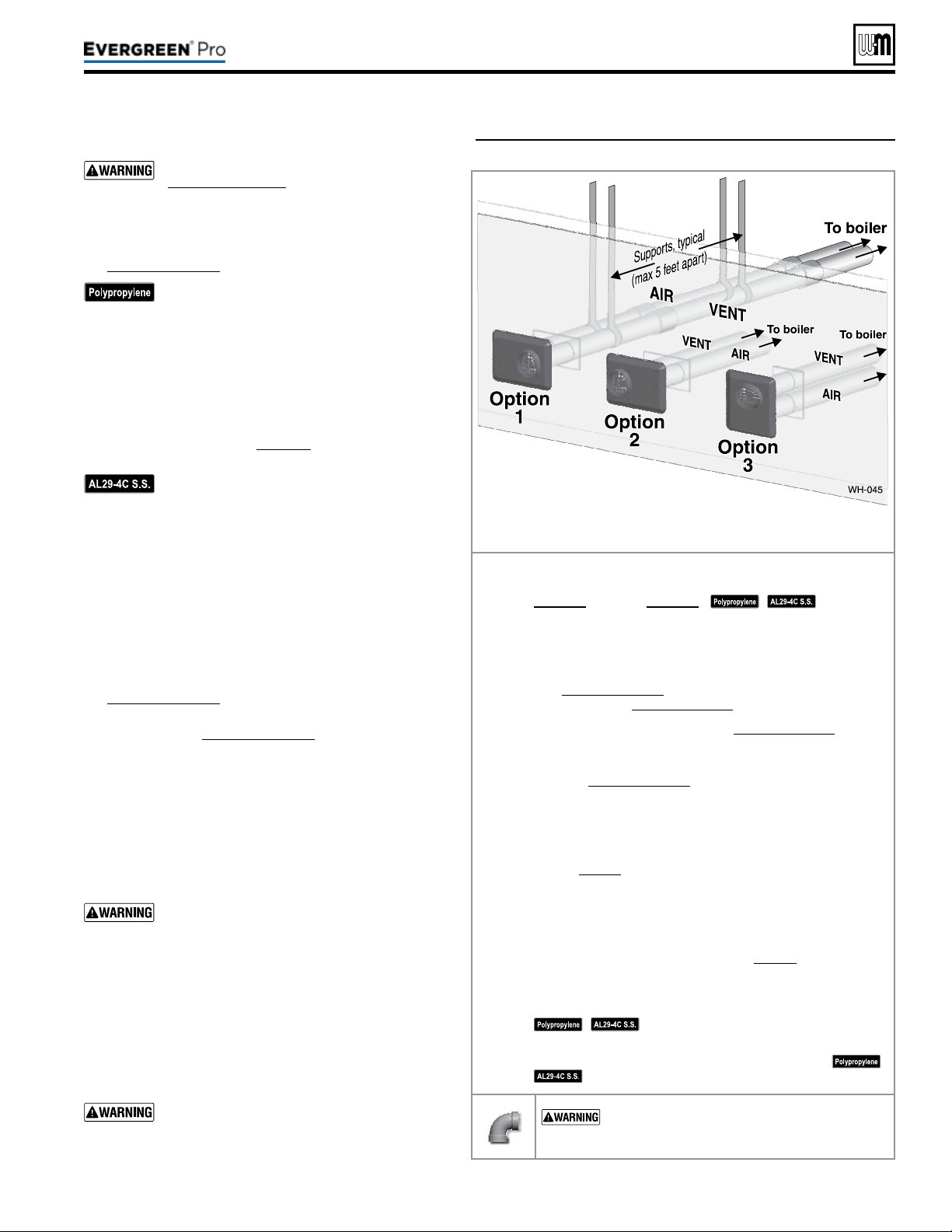
DIRECT VEN T
Figure30 INSTALLATION — W-M sidewall vent/air plate
Part number 550-100-211/0122
– 27 –
220 /29 9/3 00 /39 9
Allowablevent/airpipematerials&lengths
Use only the vent materials and kits listed in
Figure24,page21. Provide pipe adapters if
specied.
1. Locate the termination such that the total air pip-
ing and vent piping from the boiler to the termina-
tion will not exceed the maximum length given in
Figure23,page20.
For polypropylene applications, comply with
any additional requirements in the vent system
manufacturer’s instructions. Provide 4” PVC-
to-PP transition pieces at the boiler vent and
air connections. PP adapter must have smooth,
straight section of pipe to insert in to the boiler
vent and air connections and must t and seal
tightly. PP adapters with their own seal which
would interfere with the internal seal of the
boiler vent or air connections must not be
used. Refer to page117 for a list of compliant
adapters. Install a locking collar at every joint.
For AL29-4C vent pipe applications, comply
with any additional requirements in the vent
system manufacturer’s instructions. Provide 4”
PVC transition pieces at the boiler and at the
vent and air terminations. (e air pipe must
be PVC or CPVC.)
2. For 4” to 3” transitions, must use appropriate vent
material. For polypropylene or stainless steel must use
approved suppliers transitions (EVG 220 only).
Determineterminationlocation
1. Wall penetration thickness between 0” to 24”.
2. The vent/air cap must be installed as shown in
Figure33,page28.
3. e termination must comply with clearances and limita-
tions shown in Figure25,page23.
4. Locate the termination so it is not likely to be damaged
by foreign objects, such as stones or balls, or subject to
buildup of leaves or sediment.
Multiplevent/airterminationsortermination
adjacenttootherapplianceterminations
1. When terminating multiple Evergreen
®
boilers, ter-
minate each vent/air connection as described in this
manual.
All vent pipes and air inlets must terminate at
the same height to avoid possibility of severe
personal injury, death or substantial property
damage.
2. Place wall penetrations to obtain minimum clearance
as shown in for U. S. installations. For Canadian instal-
lations, provide clearances required by
Natural Gas and
Propane Installation Code, CAN/CSA
B149.1 or B149.2
and a ULCS636 compliant vent kit.
3. e air inlet of a Evergreen
®
boiler is part of a direct vent
connection. It is not classied as a forced air intake with
regard to spacing from adjacent boiler vents.
For terminations of other appliances, provide
at least the clearance shown . e installation
must also comply with the manual for the
other appliances.
Vent/airpipesandvent/aircanbeorientedasoption1,2,
or3.DONOTmountwithplateverticalandventoutletdown.
Step1 Read and follow all instructions in this manual. DONOT
proceedwithvent/airinstallationuntilyouhaveread
page19throughpage24.
See notices
at le.
Step2 Install the boiler in a location that allows proper routing of all
vent and air piping to the selected sidewall location.
Step3Make sure the selected sidewall termination location complies
with Figure25,page23. (Multiple boiler sidewall plates must
also comply with Figure28,page26.)
Step4Use only the vent materials listed in Figure24,page21. Provide
pipe adapters where required.
Step5Vent piping and air piping lengths must not exceed the values
shown in Figure23,page20.
Step6Ensure proper clearance above grade or snowline. Keep vents/
air intake area clear of accumulating snow.
Step7Prepare the sidewall penetrations and secure the sidewall plates
as instructed in this section. See “Install Weil-McLain vent/air
cap” on page28.
Step8e Weil-McLain plate termination must be installed before
piping from the boiler to the termination.
Step9Install vent and air piping between the boiler and the vent/air
termination plate. Slope horizontal piping downward toward
the boiler at least 1/4 inch per foot. See page38 for general
guidelines.
Step10Install pipe supports every 5 feet on both the horizontal and
vertical runs, or per vent pipe manufacturer’s instructions.
See notices at le.
Step11Install a hanger support within 6inches of any upturn in the
piping, or per vent pipe manufacturer’s instructions.
See notices at le.
USESWEEPELBOWSFORALLVENTANDAIR
PIPING — DO NOT use short radius elbows for vent
or air piping. Boiler performance could be aected.
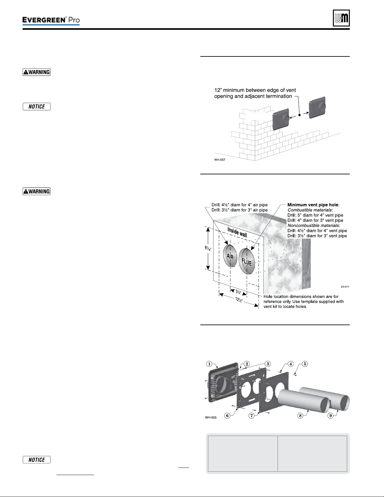
Figure31 Adjacent terminations — OUTSIDE VIEW
— clearance from air inlet to exhaust from
another appliance
DIRECT VEN T
(continued)
InstallWeil-McLainvent/aircap
ADAPTERS — Use adapters if using other than 4-inch
PVC or CPVC. is is required for dierent materials
(polypropylene or AL29-4C stainless steel) or if using
3-inch pipe.
e inside and outside cover plates are stamped to
identify the exhaust (vent) and intake (air) openings.
Make sure to orient the plates correctly.
1. Locate termination opening and avoid obstructions:
a. Use the template supplied with the termination kit.
b. Locate the template on the outside building surface where
the penetration is to be made.
c. Make sure there will be no obstructions that might prevent
proper placement of the termination.
d. Use the template to mark the locations for the four mounting
holes, ue pipe and air pipe. Level the template with a level.
For the Weil-McLain plate, the template must be level
to ensure the ue and air pipe will be side-to-side, as
shown in Figure32. Failure to comply could result in
severe personal injury, death or substantial property
damage.
e. Cut holes in the wall as shown in Figure32, using the loca-
tion marks made with the template. For best results, use a
small-diameter, long drill bit to drill centering holes for the
ue and air pipe openings. en drill the large openings from
both the inside and outside.
f. e ue pipe and air pipe may be run through a rectangular
cutout (as marked on the template) in lieu of two separate
holes if desired.
2. Drill holes for the screws or plastic anchors to secure the outside
plate. Install the outside plate and mount the termination on the
plate (temporarily).
a. Cut the ue pipe so the extension through the wall will cause
the vent pipe to fully extend into the termination socket.
b. Cut the air pipe so the extension through the wall will butt
the air pipe against the stops inside the termination.
c. Temporarily slide the flue and air pipes through the
opening(s). Slide the inside wall plate over the two pipes and
into position on the inside wall.
d. Position the inside plate so the ue pipe and air pipe slope
downward slightly toward the boiler (1/4” per foot).
e. Mark the four (4) mounting holes for the plate.
f. Remove the vent and air pipe, drill the four mounting holes,
and mount the inside plate.
3. Test t the vent/air termination on the vent pipe. Make sure the
vent pipe fully penetrates the termination socket and the air pipe
butts against the interior stops.
4. Apply silicon RTV sealant to the interior of the vent termination
and slide onto vent pipe. Rotate slightly to spread the silicon to
ensure a tight seal around the vent pipe.
5. Secure the termination in place using the four (4) #10 x ½” sheet
metal screws and lock washers (see Figure33).
Vent/air pipes and W-M vent/air plate can be ori-
ented in any of the configurations shown in Fig-
ure30,page27.
Part number 550-100-211/0122
– 28 –
1 Vent termination (4”)
2 Lock washer, #10 (4)
3 Sheet metal screw, #10 x ½” (4)
4 Plastic wall anchor (8)
5 Sheet metal screw, #10 x 1¼”
(8)
6 Outer mounting plate
7 Inner mounting plate
8 Vent pipe (butt to screen in
termination)
9 Air pipe (butt to stops in termi-
nation)
Figure32 Hole preparation in wall — INSIDE VIEW
(use template provided)
Figure33 Termination assembly — INSIDE VIEW
Weil-McLain vent/air cap and plates
220 /29 9/3 00 /39 9
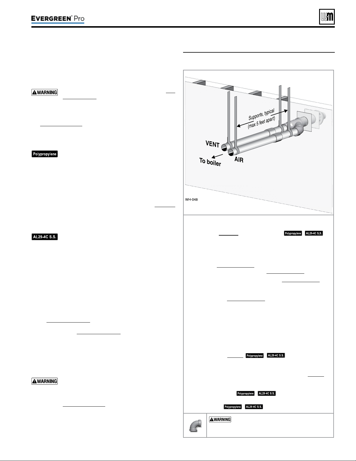
Instructions below - are for the WM 3” and 4” PVC
Concentric Kit. If using Simpson-Duravent or Centrotherm
Concentric kit, please refer to the manufacturer’s installation
instructions.
Allowablevent/airpipematerials&lengths
1. e concentric termination kit must be purchased separately.
Use only the vent materials and kits listed in Fig-
ure24,page21. Provide pipe adapters if specied.
2. Locate the termination such that the total air pip-
ing and vent piping from the boiler to the termina-
tion will not exceed the maximum length given in
Figure23,page20.
3.
is termination requires a 45-degree elbow that is not sup-
plied with the termination kit. e maximum vent/air pipe
len
gths include allowance for this elbow.
For polypropylene applications, comply with
any additional requirements in the vent system
manufacturer’s instructions. Provide 4” PVC-to-
PP transition pieces at the boiler vent and air con-
nections. PP adapter must have smooth, straight
section of pipe to insert in to the boiler vent and
air connections and must t and seal tightly. PP
adapters with their own seal which would inter-
fere with the internal seal of the boiler vent or air
connections must not be used. Refer to page117
for a list of compliant adapters. Install a locking
collar at every joint.
For AL29-4C vent pipe applications, comply with
any additional requirements in the vent system
manufacturer’s instructions. Provide a 4”PVC
transition at the boiler vent connection. Air pipe
must be PVC or CPVC. Provide transition pieces
to PVC at the vent and air pipe termination con-
nections.
4. For 4” to 3” transitions, must use appropriate vent material.
For polypropylene or stainless steel must use approved sup-
pliers transitions (EVG 220 only).
Determineterminationlocation
1. Wall penetration thickness between 0” to 24”.
2. e concentric termination kit must be installed as shown
in Figure36,page30.
3. e termination must comply with clearances and limita-
tions shown in Figure25,page23.
4. Locate the termination so it is not likely to be damaged
by foreign objects, such as stones or balls, or subject to
buildup of leaves or sediment.
Multiplevent/airterminations
1. When terminating multiple Evergreen
®
boilers, install each
concentric termination as described in this manual.
All vent pipes and air inlets must terminate at the same
height to avoid possibility of severe personal injury,
death or substantial property damage.
2. Place wall penetrations to obtain minimum clearance as
shown in Figure36,page30 for U. S. installations. For Ca-
nadian installations, provide clearances required by Natural
Ga
s and Propane Installation Code,
CAN/CSA B149.1 or
B149.2 Installation Code and a ULCS636 compliant vent kit.
3. e air inlet of a Evergreen
®
boiler is part of a direct vent
connection. It is not classied as a forced air intake with
regard to spacing from adjacent boiler vents.
Figure34 INSTALLATIONSEQUENCE — Concentric
horizontal
Step1 Read and follow all instructions in this manual. DONOT
proceed with vent/air installation until you have
readpage19throughpage24.
See
notices at le.
Step2 Install the boiler in a location that allows proper routing of all
vent and air piping to the selected sidewall location.
Step3 Make sure the selected sidewall termination location complies
with Figure25,page23. (Multiple boiler concentric termina-
tions must also comply with Figure35,page30.)
Step4 Use only the vent materials listed in Figure24,page21. Pro-
vide pipe adapters where required.
Step5 Vent piping and air piping lengths must not exceed the values
shown in Figure23,page20.
Step6 Ensure proper clearance above grade or snowline. Keep vents/
air intake area clear of accumulating snow.
Step7 e concentric termination must be assembled and installed
before piping from the boiler to the termination.
Step8 Prepare the sidewall penetration — assemble the concentric
termination kit and secure the cover plates as instructed in
this section. Provide the supports indicated and mount the
termination assembly. See “Install termination — concentric
pipes” on page30.
See notices at le.
Step9 Install vent and air piping between the boiler and the concen-
tric vent/air termination. Slope horizontal piping downward
toward the boiler at least 1/4 inch per foot. See page38 for
general guidelines.
Step10 Install pipe supports every 5 feet on both the horizontal and
vertical runs.
See notices at le.
Step11 Install a hanger support within 6inches of any upturn in the
piping.
See notices at le.
USESWEEPELBOWSFORALLVENTAND
AIRPIPING — DO NOT use short radius elbows
for vent or air piping. Boiler performance could be
aected.
Part number 550-100-211/0122
– 29 –
220 /29 9/3 00 /39 9
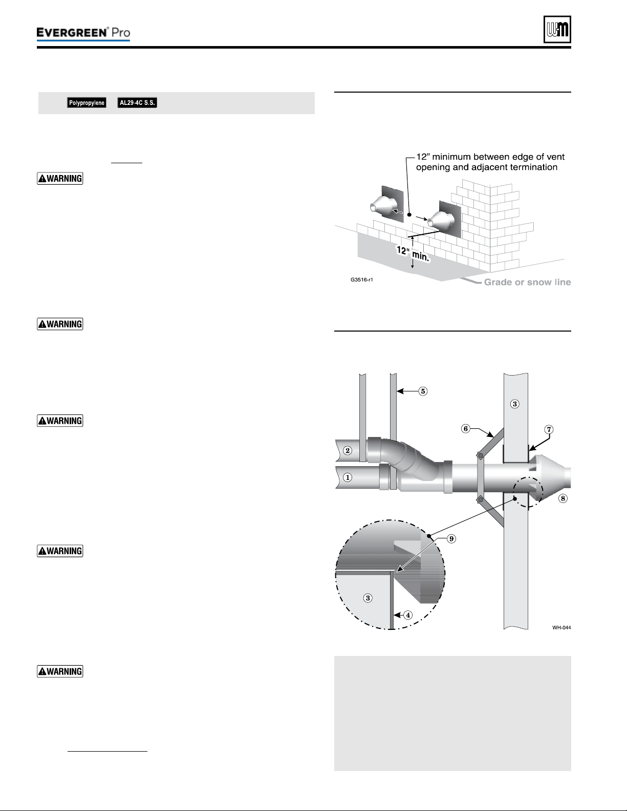
(continued)
Figure35 Termination location — concentric
termination — multiple boilers —
clearance from vent of one to air intake of
the next
Figure36 Installing and supporting the concentric
sidewall vent assembly
LEGEND
1 Vent pipe.
2 Air pipe.
3 Wall.
4 Outer thimble plate.
5 Supports every 5 feet or
per vent pipe mfr’s in-
structions.
6 Wall brace, by installer,
(or see vent pipe mfr’s
instructions).
7 imble, by installer.
8 Rain cap.
9 Rain cap ribs must butt
against outer thimble
plate or wall opening.
See notices on previous page.
Part number 550-100-211/0122
– 30 –
Installtermination—concentricpipes
1. Assemble the vent termination as described for concentric ter-
minations, on page35.
If necessary, you can shorten the lengths of the inner
and outer pipes for a shorter nished assembly. But you
must ensure the pipes butt correctly at both ends. Failure
to properly assemble the concentric termination can
result in ue gas recirculation, causing possible severe
personal injury or death.
2. Wall penetration:
a. Preferably, use a thimble with a 5½-inch hole (4” Concentric
Kit) or a 4½-inch hole (3” Concentric Kit). If not using a
thimble, carefully use a hole saw to cut a hole not larger than
5¾ or 4¾ inches in diameter through the wall. e nished
hole must provide a solid stop for the rain cap ribs, as shown
in the inset to Figure36.
Ensure that the wall material is strong enough to pre-
vent the rain cap from being pushed inward if struck or
pushed from the outside.
3. Secure the termination in place so the rain cap will butt against
the outside wall or outer thimble plate as shown in Figure36.
4. Before beginning vent and air piping from the boiler to the con-
centric termination, mount and secure the concentric termination
as shown in Figure36.
e vent and air piping must be securely supported, and
must not rest its weight on the boiler ttings. Failure to
properly support the vent and air piping could result in
vent piping damage, resulting in possible severe personal
injury, death or substantial property damage.
e supports/bracing used must support the termina-
tion assembly to prevent slippage or movement. See
instructions provided with concentric kit for details.
e clamps used on the outside of the termination pipe
must not cut into the pipe or contain sharp edges that
could cause a crack to form.
When inserting the partially-assembled termination
kit through the wall penetration, wrap plastic or other
protection over the end of the exposed assembly to pre-
vent debris from entering the pipes. If the air passages
become blocked, the boiler will not operate. Once the
rain cap has been cemented to the assembly, there is no
way to correct the problem. e assembly would have
to be replaced if it were cut to be removed and cleaned.
Altering the assembly in any way could result in severe
personal injury or death due to toxic ue product emis-
sions.
If using AL29-4C stainless vent pipe, use the vent pipe
manufacturer’s PVC adapter if connecting to a PVC
concentric vent attachment.
5. Aer the assembly has been positioned in the opening and all
supports have been attached, install a bird screen (purchased
separately if not included with the kit) and rain cap as follows:
a. Place the bird screen on the end of the inner pipe as in
Figure42,page35, or per concentric kit instructions for
polypropylene kits.
b. Cement the rain cap in place as shown.
220 /29 9/3 00 /39 9
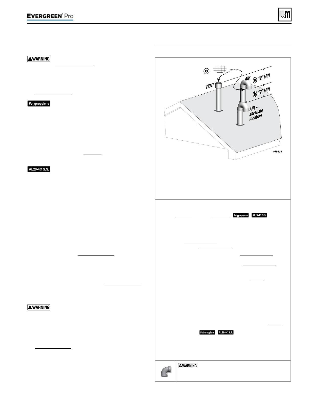
Allowablevent/airpipematerials&lengths
Use only the vent materials and kits listed in
Figure24,page21. Provide pipe adapters if
specied.
1. Locate the terminations such that the total air pip-
ing and vent piping from the boiler to the termina-
tion will not exceed the maximum length given in
Figure23,page20.
For polypropylene applications, comply with
any additional requirements in the vent system
manufacturer’s instructions. Provide 4” PVC-
to-PP transition pieces at the boiler vent and
air connections. PP adapter must have smooth,
straight section of pipe to insert in to the boiler
vent and air connections and must t and seal
tightly. PP adapters with their own seal which
would interfere with the internal seal of the
boiler vent or air connections must not be
used. Refer to page117 for a list of compliant
adapters. Install a locking collar at every joint.
For AL29-4C vent pipe applications, comply
with any additional requirements in the vent
system manufacturer’s instructions. Provide a
4”PVC transition piece at the boiler vent con-
nection. e air piping must be PVC or CPVC.
2. For 4” to 3” transitions, must use appropriate vent
material. For polypropylene or stainless steel must use
approved suppliers transitions (EVG 220 only).
Determineterminationlocation
1. Wall penetration thickness between 0” to 24”.
2. e air and vent terminations must be installed as shown
in Figure37.
3. The terminations must comply with clearances and
limitations shown in Figure25,page23.
4. Locate the terminations so they are not likely to be dam-
aged by foreign objects, such as stones or balls, or subject
to buildup of leaves or sediment.
Multiplevent/airterminations(Figure38,page32)
1. When terminating multiple Evergreen
®
boilers, terminate
each vent/air connection as described in this section.
Terminate all vent pipes at the same height
and all air pipes at the same height to avoid
possibility of severe personal injury, death or
substantial property damage.
2. Place roof penetrations to obtain minimum clearance of
12inches between edge of air intake elbow and adjacent
vent pipe of another boiler for U. S. installations (see
Figure38,page32). For Canadian installations, provide
clearances required by
Natural Gas and Propane Instal-
lation Code, CAN/CSA
B149.1 or B149.2 Installation
Code and a ULCS636 compliant vent kit.
3. e air inlet of a Evergreen
®
boiler is part of a direct vent
connection. It is not classied as a forced air intake with
regard to spacing from adjacent boiler vents.
Figure37 Separate pipes vertical termination
Terminateventandairpipessuchthat:
a AIRINTAKEIS AT LEAST 12 inches below vent outlet.
b AIRINTAKEIS AT LEAST 12 inches above roof or snow line,
Keep vents/air intake area clear of accumulating snow.
c Ventandairterminationsarettedwithbirdscreens.
Step1 Read and follow all instructions in this manual. DO NOT
proceedwithvent/airinstallationuntilyouhaveread
page19throughpage24.
See notices
at le.
Step2 Install the boiler in a location that allows proper routing of all
vent and air piping to the selected location.
Step3 Make sure the selected vertical termination location complies
with Figure25,page23. (Multiple boiler terminations must also
comply with Figure38,page32.)
Step4 Use only the vent materials listed in Figure24,page21. Provide
pipe adapters where required. Vent piping and air piping lengths
must not exceed the values shown in Figure23,page20.
Step5 Prepare the vertical penetrations and secure penetration com-
ponents as instructed in this section. See “Prepare roof penetra-
tions” and “Termination and ttings” on page32.
Step6 e air piping must terminate in a 180-degree return bend or
down-turnedelbow as shown above. e vent piping must
terminate in a couplingpointedupward as shown above.
Step7 Install vent and air piping between the boiler and the vertical
terminations. Slope horizontal piping downward toward the
boiler at least 1/4 inch per foot. Install pipe supports every 5 feet
on both the horizontal and vertical runs. Install a hanger sup-
port within 6inches of any upturn in the piping. See page38 for
general guidelines. Also comply with vent pipe manufacturer’s
instructions.
See notices at le.
Step8 Insert the vent and air piping through the vertical penetrations
and secure the termination ttings.
Step9 Maintain clearances shown above. Vent and air terminations
must be tted with a bird screen as shown.
USESWEEPELBOWSFORALLVENTAND
AIRPIPING — DO NOT use short radius elbows
for vent or air piping. Boiler performance could be
aected.
Part number 550-100-211/0122
– 31 –
220 /29 9/3 00 /39 9
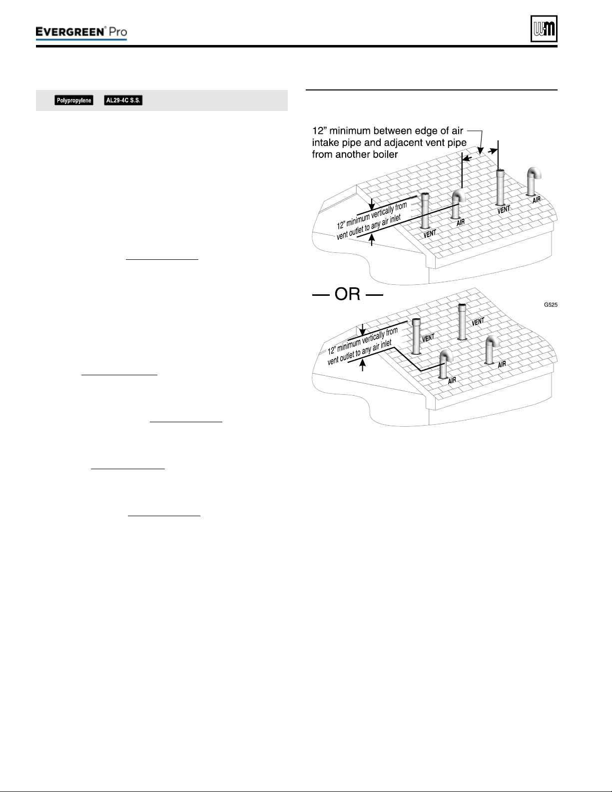
Figure38 Terminations for multiple boilers
Prepareroofpenetrations
1. Air pipe penetration:
a. Cut a hole for the air pipe. Size the air pipe hole as close
as desired to the air pipe outside diameter.
2. Vent pipe penetration:
a. Cut a hole for the vent pipe. For either combustible or
noncombustible construction, size the vent pipe hole at
least 0.4” larger than the vent pipe diameter.
b. Insert a galvanized metal thimble in the vent pipe hole.
3. Space the air and vent holes no closer than the minimum
spacings shown in Figure38,page32.
4. Follow all local codes and vent pipe manufacturer’s instruc-
tions for isolation of vent pipe when passing through oors,
ceilings and roofs.
5. Provide ashing and sealing boots sized for the vent pipe and
air pipe. Follow all vent pipe manufacturer’s instructions.
Terminationandttings
1. Prepare the vent termination elbow and the air termination
elbow (Figure37,page31) by inserting bird screens. Bird
screens must be purchased separately. See the parts list at the
end of this manual for part numbers.
2. e air piping must terminate in a down-turned 180-degree
return bend as shown in Figure37,page31. e edge of the
air inlet elbow must be at least 12 inches above the roof or
snow line.
3. e vent piping must terminate in an up-turned coupling as
shown in Figure37,page31. e top of the coupling must
be at least 12 inches above the air intake in order to avoid the
recirculation of ue products into the combustion air stream.
4. Maintain the required dimensions of the nished termination
piping as shown in Figure37,page31.
5. Do not extend exposed vent pipe outside of building more
than shown in this document. Condensate could freeze and
block vent pipe.
See notices on previous page.
Part number 550-100-211/0122
– 32 –
DIRECT VEN T
(continued)
220 /29 9/3 00 /39 9
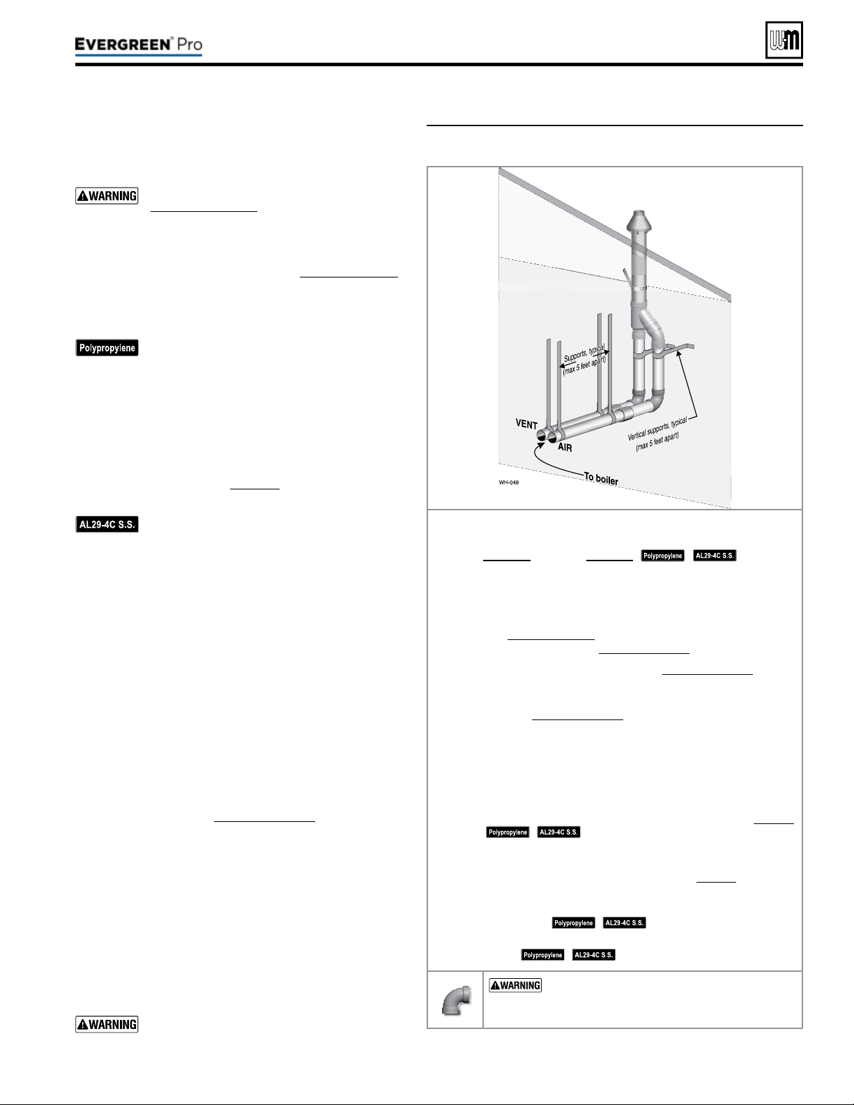
Allowablevent/airpipematerials&lengths
1. The concentric termination kit must be purchased
separately.
Use only the vent materials and kits listed in
Figure24,page21. Provide pipe adapters if
specied.
2. Locate the termination such that the total air piping and
vent piping from the boiler to the termination will not
exceed the maximum length given in Figure23,page20.
3. is termination requires a 45-degree elbow that is not
supplied with the termination kit. e maximum vent/
air pipe lengths include allowance for this elbow.
For polypropylene applications, comply with
any additional requirements in the vent system
manufacturer’s instructions. Provide 4” PVC-
to-PP transition pieces at the boiler vent and
air connections. PP adapter must have smooth,
straight section of pipe to insert in to the boiler
vent and air connections and must t and seal
tightly. PP adapters with their own seal which
would interfere with the internal seal of the
boiler vent or air connections must not be
used. Refer to page117 for a list of compliant
adapters. Install a locking collar at every joint.
For AL29-4C vent pipe applications, comply
with any additional requirements in the vent
system manufacturer’s instructions. Provide a
4”PVC transition at the boiler vent connec-
tion. Air pipe must be PVC or CPVC. Provide
transition pieces to PVC at the vent and air pipe
termination connections.
4. For 4” to 3” transitions, must use appropriate vent
material. For polypropylene or stainless steel must use
approved suppliers transitions (EVG 220 only).
Determineterminationlocation
Locate the concentric vent/air termination using the fol-
lowing guidelines:
1. Wall penetration thickness between 0” to 24”.
2. e concentric vent/air assembly must terminate as
shown in these instructions.
3. e termination must comply with the clearances and
limitations shown in Figure25,page23.
4. Locate the termination so it is not likely to be damaged
by foreign objects, such as stones or balls, or subject to
buildup of leaves or sediment.
5. For Canadian installations, follow requirements of
Natural Gas and Propane Installation Code, CAN/CSA
B149.1 or B149.2 and a ULCS636 compliant vent kit.
Multiplevent/airterminations
1. When terminating multiple Evergreen
®
boilers, install the
concentric vent/air termination assemblies as described
in this manual.
All vent outlets must terminate at the same
height to avoid possibility of severe personal
injury, death or substantial property damage.
Figure39 INSTALLATIONSEQUENCE — Concentric vertical
Step1 Read and follow all instructions in this manual. DO NOT
proceedwithvent/airinstallationuntilyouhaveread
page19throughpage24.
See notices
at le.
Step2 Install the boiler in a location that allows proper routing of all
vent and air piping to the selected location.
Step3 Make sure the selected vertical termination location complies
with Figure25,page23. (Multiple boiler concentric terminations
must also comply with Figure40,page34.)
Step4 Use only the vent materials listed in Figure24,page21. Provide
pipe adapters where required.
Step5 Vent piping and air piping lengths must not exceed the values
shown in Figure23,page20.
Step6 e concentric termination must be assembled and installed
before piping from the boiler to the termination.
Step7 Prepare the vertical penetration(s) — assemble the concen-
tric termination kit and secure the penetration components
as instructed in this section. Provide the supports indicated
and mount the termination assembly. See “Prepare roof pen-
etrations” and “Mount concentric termination” on page34.
See notices at le.
Step8 Install vent and air piping between the boiler and the concentric
vent/air termination. Slope horizontal piping downward toward
the boiler at least 1/4 inch per foot. See page38 for general
guidelines.
Step9 Install pipe supports every 5 feet on both the horizontal and
vertical runs.
See notices at le.
Step10 Install a hanger support within 6inches of any upturn in the
piping.
See notices at le.
USESWEEPELBOWSFORALLVENTAND
AIR PIPING — DO NOT use short radius elbows
for vent or air piping. Boiler performance could be
aected.
Part number 550-100-211/0122
– 33 –
220 /29 9/3 00 /39 9
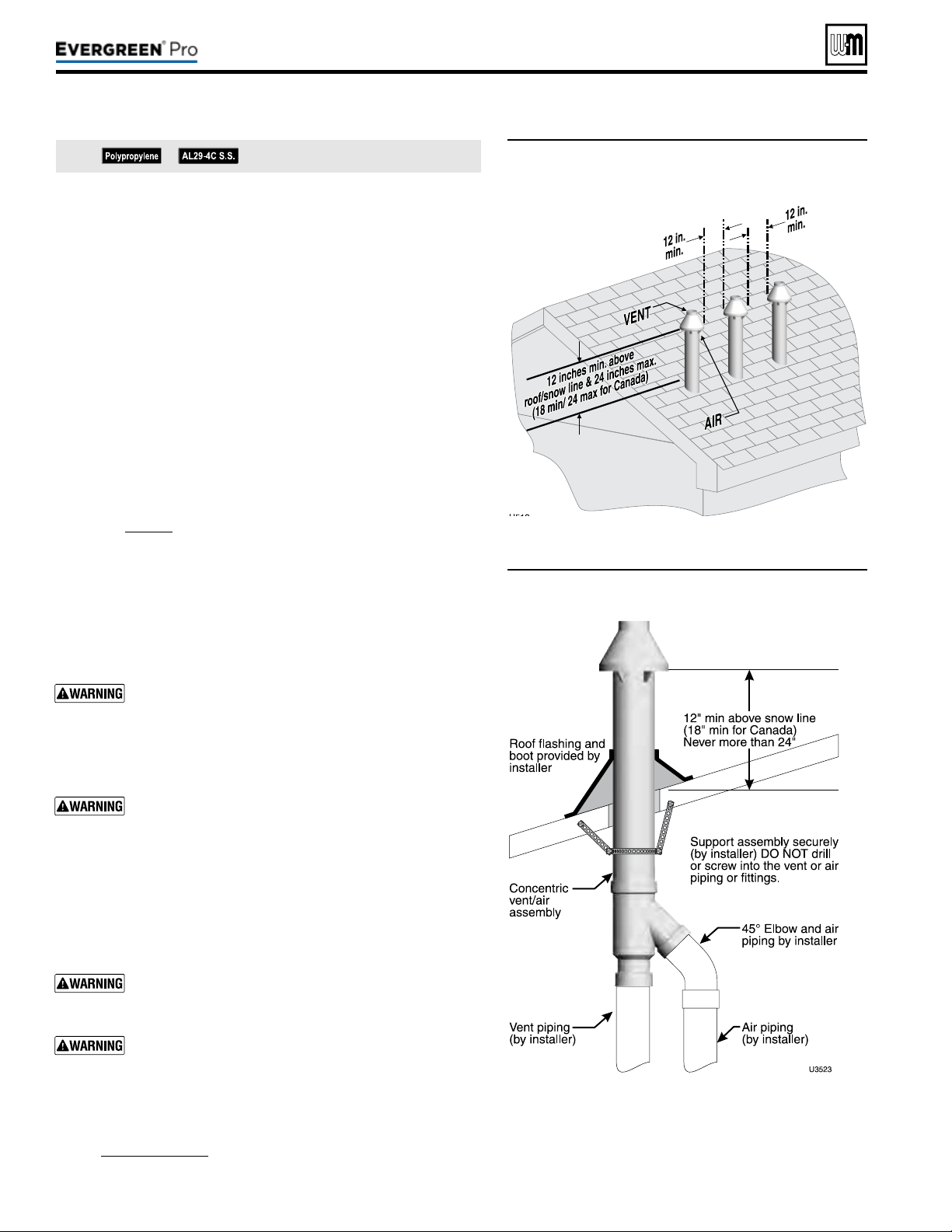
(continued)
2. Place roof penetrations to obtain minimum of 12inches between
centers of adjacent vent pipe of another boiler for U. S. installations
(see Figure40).
3. e air inlet of a Evergreen
®
boiler is part of a direct vent connec-
tion. It is not classied as a forced air intake with regard to spacing
from adjacent boiler vents.
Prepareroofpenetrations
1. Roof penetration hole:
a. Cut a clearance hole to clear the termination outside diameter
as prescribed in the kit instructions.
b. Insert a galvanized metal thimble in the vent pipe hole.
2. Follow all local codes for isolation of vent pipe when passing
through oors, ceilings and roofs.
3. Provide ashing and sealing boots sized for the concentric termina-
tion outside diameter.
Mountconcentrictermination
1. Assemble the vent termination as described for concentric termi-
nation, page35.
2. Mount the termination as shown in Figure41.
3. Support the concentric vent/air termination at the roof penetration
as shown in Figure41 or per concentric kit instructions.
y e supports/bracing used must support the termination as-
sembly to prevent vertical slippage or sideways movement.
y e clamps used on the outside of the termination pipe must
not cut into the pipe or contain sharp edges that could cause
a crack to form.
e vent and air piping must be securely supported, and
must not rest its weight on the boiler ttings. DO NOT
drill or screw into either the vent pipe or air pipe. Failure
to properly support the vent and air piping could result in
vent piping damage, resulting in possible severe personal
injury, death or substantial property damage.
When inserting the partially-assembled termination kit
through the roof penetration, wrap plastic or other pro-
tection over the end of the exposed assembly to prevent
debris from entering the pipes. If the air passages become
blocked, the boiler will not operate. Once the rain cap has
been cemented to the assembly, there is no way to correct
the problem. e assembly would have to be replaced if
it were cut to be removed and cleaned. Altering the as-
sembly in any way could result in severe personal injury
or death due to toxic ue product emissions.
If using AL29-4C stainless vent pipe, use the vent pipe
manufacturer’s PVC adapter if connecting to a PVC
concentric vent attachment.
Do not connect any other appliance to the vent pipe or
multiple boilers to a common vent pipe.
4. Aer the assembly has been positioned in the roof opening and
all supports have been attached, install a bird screen (purchased
separately if not included with the kit) and rain cap as follows:
a. Place the bird screen on the end of the inner pipe as in
Figure42,page35, or per kit instructions for polypropylene kits.
b. Cement the rain cap in place.
Figure40 Vertical termination — concentric
termination — single or multiple boilers
Figure41 PVC concentric termination supports
See notices on previous page.
Part number 550-100-211/0122
– 34 –
220 /29 9/3 00 /39 9
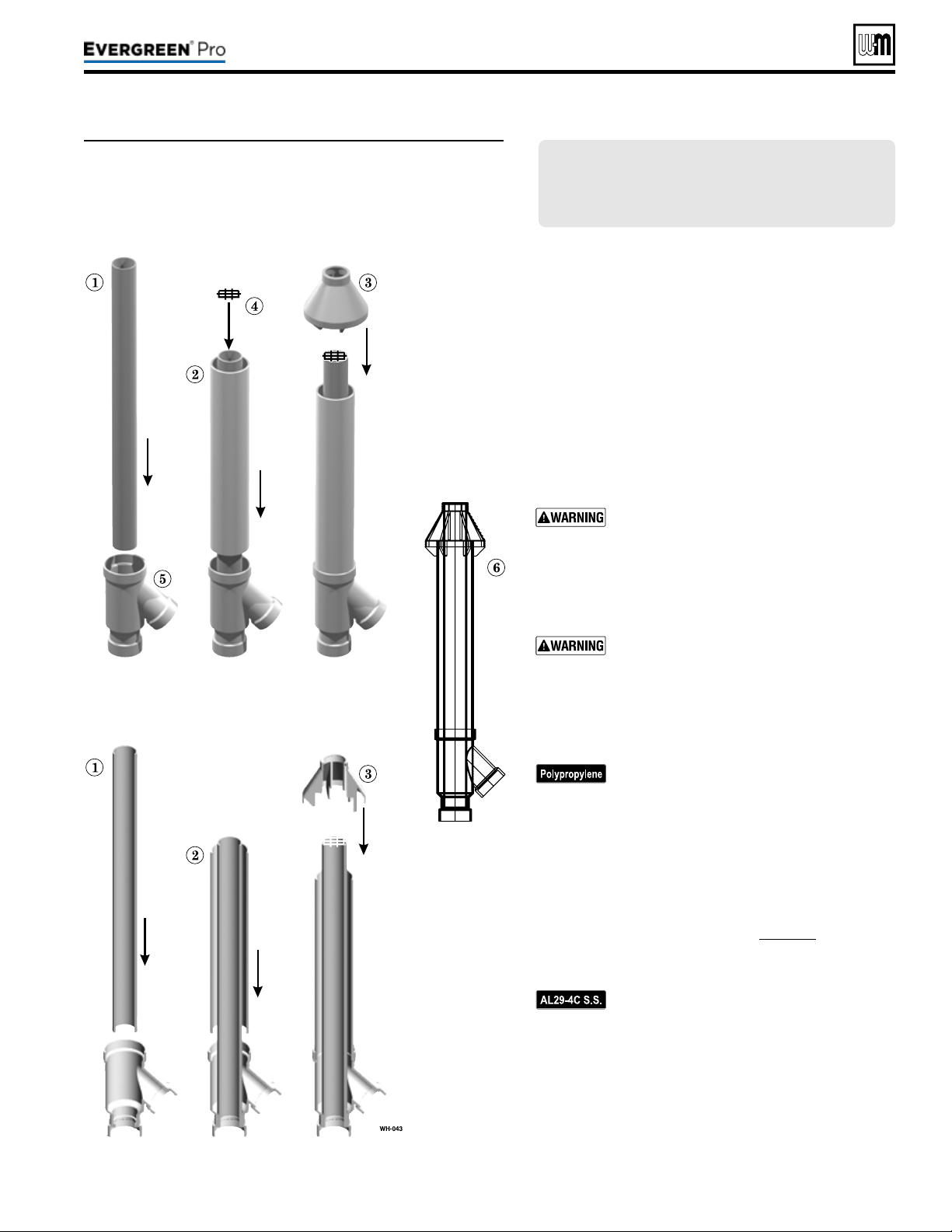
Figure42 PVC concentric termination assembly — DO NOT
attach the rain cap until the termination has been
inserted through the roof or wall and all supports
have been installed. See LEGEND at right. See kit
instructions for details of polypropylene kits.
Part number 550-100-211/0122
– 35 –
220 /29 9/3 00 /39 9
(sidewall or vertical)
Assemblingconcentrictermination
1. Follow all instructions provided with the concentric
termination kit. e following are general guidelines
for information only.
2. See Figure42 for the typical assembly of a concentric
termination assembly.
3. Prepare the bird screen, item4 (purchase separately if
not included with the kit). Cut the bird screen to size
if required. If the bird screen must be trimmed, cut the
bird screen to t the outside diameter of the PVC inner
pipe supplied with the termination kit.
4. Partially assemble the vent termination kit in the se-
quence shown in Figure42, or per the concentric kit
instructions.
DONOT install the rain cap and bird screen
until the assembly has been inserted through
the roof (or sidewall) and all supports have
been installed. Follow instructions to cover
the end of the assembly with plastic before
inserting through the roof penetration to
prevent debris from blocking the air passages.
If necessary, you can shorten the lengths of the
inner and outer pipes for a shorter nished
assembly. But you must ensure the pipes butt
correctly at both ends. Failure to properly as-
semble the concentric termination can result
in ue gas recirculation, causing possible
severe personal injury or death.
For polypropylene applications, comply with
any additional requirements in the vent sys-
tem manufacturer’s instructions. Provide 4”
PVC-to-PP transition pieces at the boiler vent
and air connections. PP adapter must have
smooth, straight section of pipe to insert in to
the boiler vent and air connections and must
t and seal tightly. PP adapters with their own
seal which would interfere with the internal
seal of the boiler vent or air connections must
not be used. Refer to page117 for a list of
compliant adapters. Install a locking collar
at every joint.
For AL29-4C vent pipe applications, comply
with any additional requirements in the vent
system manufacturer’s instructions. Provide
a 4”PVC transition at the boiler vent connec-
tion. Air pipe must be PVC or CPVC. Provide
transition pieces to PVC at the vent and air
pipe termination connections.
5. For 4” to 3” transitions, must use appropriate vent
material. For polypropylene or stainless steel must use
approved suppliers transitions (EVG 220 only).
LEGENDforFigure42 — Inner PVC pipe (vent)
1 —Inner PVC pipe (vent)
2 —Outer PVC pipe (air)
3 —Rain cap
4 —Bird screen
5 —Y tting
6 —Finished assembly
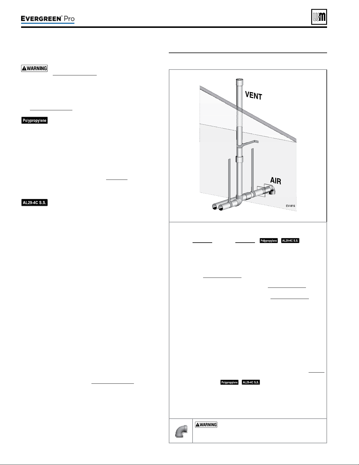
DIRECT VEN T
Figure43 INSTALLATIONSEQUENCE — Vertical vent/
sidewall air
Allowablevent/airpipematerials&lengths
Use only the vent materials and kits listed in
Figure24,page21. Provide pipe adapters if
specied.
1. Locate the terminations such that the total air pip-
ing and vent piping from the boiler to the termina-
tion will not exceed the maximum length given in
Figure23,page20.
For polypropylene applications, comply with
any additional requirements in the vent sys-
tem manufacturer’s instructions. Provide 4”
PVC-to-PP transition pieces at the boiler vent
and air connections. PP adapter must have
smooth, straight section of pipe to insert in to
the boiler vent and air connections and must
t and seal tightly. PP adapters with their own
seal which would interfere with the internal
seal of the boiler vent or air connections must
not be used. Refer to page117 for a list of
compliant adapters. Install a locking collar at
every joint.
For AL29-4C vent pipe applications, comply
with any additional requirements in the vent
system manufacturer’s instructions. Provide
a 4”PVC transition piece at the boiler vent
connection. e air piping must be PVC or
CPVC.
2. For 4” to 3” transitions, must use appropriate vent
material. For polypropylene or stainless steel must use
approved suppliers transitions (EVG 220 only).
Prepareroofpenetration
1. Vent pipe penetration:
a. Cut a hole for the vent pipe. For either combustible
or noncombustible construction, size the vent pipe
hole at least 0.4” larger than the vent pipe diameter.
b. Insert a galvanized metal thimble in the vent pipe
hole.
2. Follow all local codes for isolation of vent pipe when
passing through oors, ceilings and roofs.
3. Provide ashing and sealing boots sized for the vent
pipe and air pipe.
Ventterminationandttings
1. Prepare the vent termination coupling by inserting a bird
screen. Bird screens must be purchased separately. See
the parts list at the end of this manual for part numbers.
2. Maintain the required dimensions of the nished termi-
nation piping as shown in Figure44,page37.
Multipleventterminations
1. When terminating multiple Evergreen boilers, ter-
minate each vent/air connection as described in this
section.
2. Place adjacent terminations at least 6 inches apart.
3. For Canadian installations, provide clearances required
by Natural Gas and Propane Installation
CAN/CSA
B149.1 or B149.2 Installation Code.
Part number 550-100-211/0122
– 36 –
Step1 Read and follow all instructions in this manual. DO NOT
proceedwithvent/airinstallationuntilyouhaveread
page19throughpage24.
See notices
at le.
Step2 Install the boiler in a location that allows proper routing of all
vent and air piping to the selected locations.
Step3 Make sure the selected vertical termination location complies
with Figure25,page23.
Step4 Use only the vent materials listed in Figure24,page21. Provide
pipe adapters where required. Vent piping and air piping lengths
must not exceed the values shown in Figure23,page20.
Step5 Prepare the vertical penetration (vent) and sidewall penetra-
tion (air) and secure penetration components as instructed in
this section.
Step6 e air piping must terminate in a 90-degree down-turned
elbow as shown above. e vent piping must terminate in a
couplingpointedupward as shown above.
Step7 Install vent and air piping between the boiler and the air and
vent terminations. Slope horizontal piping downward toward
the boiler at least 1/4 inch per foot. Install pipe supports every
5 feet on both the horizontal and vertical runs. Install a hanger
support within 6inches of any upturn in the piping. See page38
for general guidelines. Also comply with vent pipe manufacturer’s
instructions.
See notices at le.
Step8 Insert the vent and air piping through the penetrations and secure
the termination ttings.
Step9 Maintain clearances shown in this section. Vent and air termina-
tions must be tted with bird screens as shown.
USESWEEPELBOWSFORALLVENTAND
AIR PIPING — DO NOT use short radius elbows
for vent or air piping. Boiler performance could be
aected.
220 /29 9/3 00 /39 9
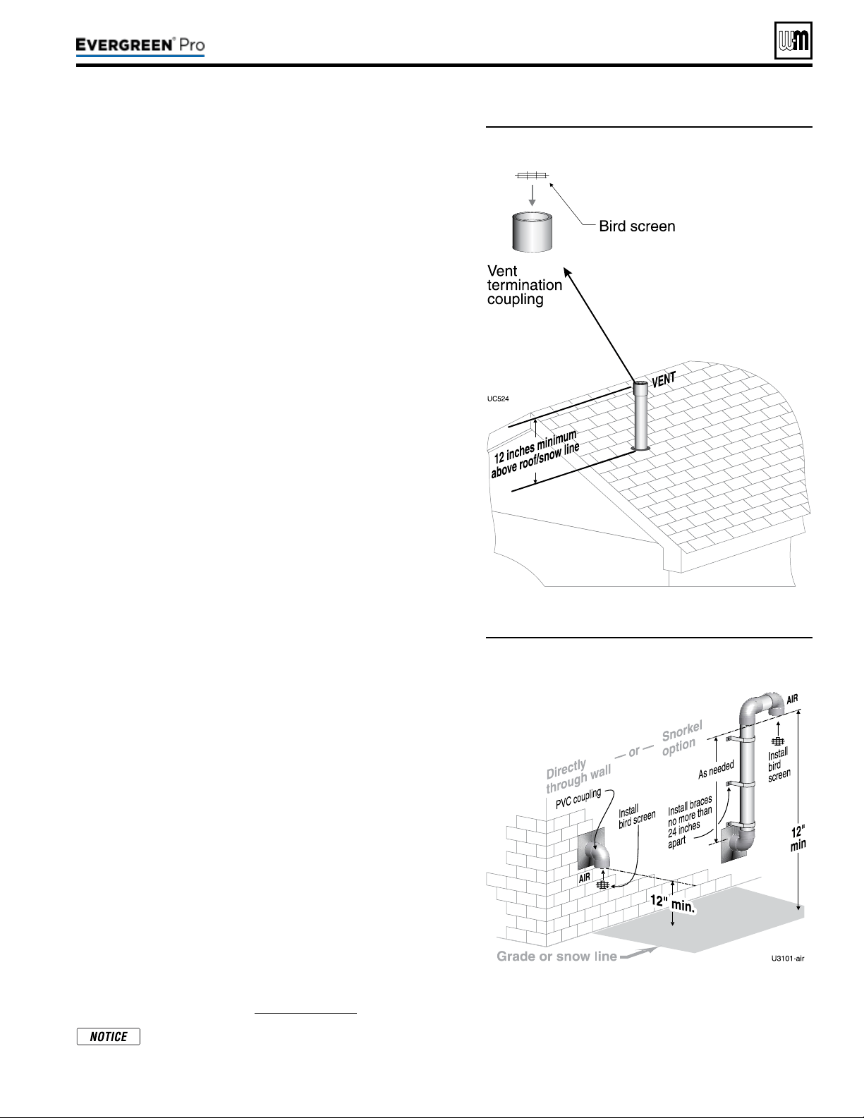
DIRECT VEN T
(continued)
Figure44 Vent termination (through the roof) for
direct vent: vertical vent / sidewall air
Figure45 Sidewall air inlet (termination) for direct
vent: vertical vent / sidewall air
Determinelocationforairinletelbow
1. e air inlet of an Evergreen boiler is part of a direct vent con-
nection. It is not classied as a forced air intake with regard to
spacing from adjacent appliance terminations.
2. Locate the air inlet elbow (termination) using the following
guidelines.
3. e air piping must terminate in a down-turned elbow as shown
in Figure45.
a. Apply the conguration on the le side of Figure45 unless
the terminations would fail to meet minimum clearance to
grade or snow line.
b. Apply the conguration on the right side of Figure45 when
the terminations need to be raised higher to meet clearance
to grade or snow line.
c. e air pipe may run up the side of the building, as shown.
e vent and air pipes must be secured with braces, and all
clearances and lengths must be maintained. Space braces no
further than 24 inches apart.
4. You must consider the surroundings when terminating the air
connection:
a. Make sure there are no obstructions for air ow. DO NOT
locate the termination where plants could grow and cause
obstruction to air ow.
b. Do not locate the terminations where wind eddies could af-
fect performance or cause recirculation with exhaust from
other appliances, such as inside building corners, near adja-
cent buildings or surfaces, window wells, stairwells, alcoves,
courtyards or other recessed areas.
c. Locate the air inlet termination at least 12 inches below and 12
inches horizontally from any appliance or building vent outlet.
5. Locate terminations so they are not likely to be damaged by
foreign objects, such as stones or balls, or subject to buildup of
leaves or sediment.
Multipleairterminations
1. When terminating multiple Evergreen boiler air connections,
terminate each air connection as described in this manual.
2. Place wall penetrations to obtain minimum clearances as in-
structed in this manual.
3. Place adjacent air inlets for multiple Evergreen boilers at least
6inches apart.
4. For Canadian installations, provide clearances required by Natu-
ral Gas and Propane Installation
CAN/CSA
B149.1 or B149.2
Installation Code.
5. Combustion air (NOT vent piping) can be manifolded as shown
in the Evergreen Advanced manual.
Preparewallpenetrations
1. Air pipe penetration:
a. Cut a hole for the air pipe. Size the air pipe hole as close as
desired to the air pipe outside diameter.
2. Seal exterior openings thoroughly with exterior caulk.
Terminationandttings
1. Prepare the air termination elbow (Figure45) by inserting a bird
screen. Bird screens must be purchased separately. See the parts
list at the end of this manual for part numbers.
2. Use metal plates (by installer) at inside and outside penetrations
using the method shown in Figure29,page26.
If extending the air pipe out from the wall, install a cou-
pling on each pipe. Mount the piping with the coupling
ush with the outer plate.
Part number 550-100-211/0122
– 37 –
220 /29 9/3 00 /39 9
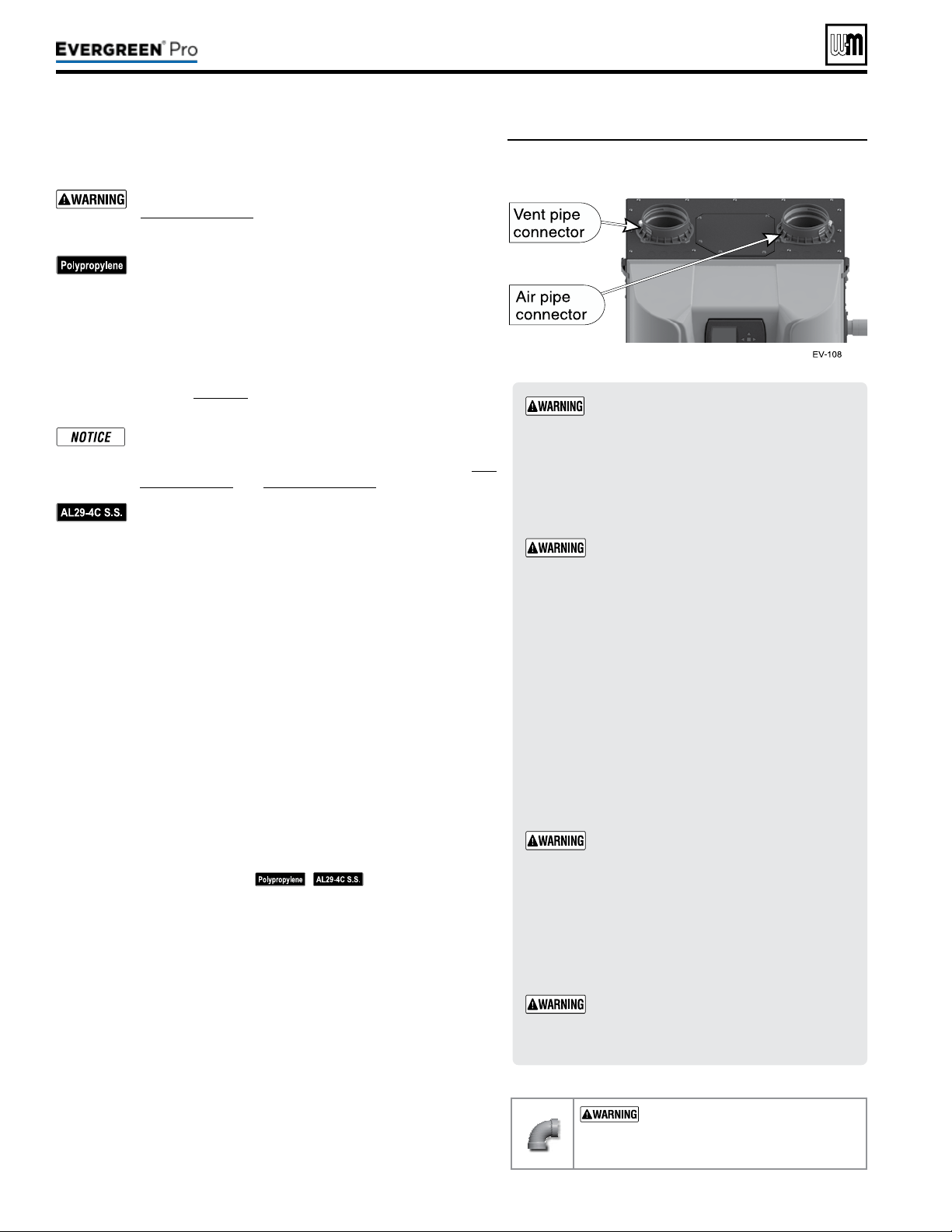
Figure46 Boiler vent and air connections
Part number 550-100-211/0122
– 38 –
ADAPTERS
— Use adapters if using other than
4-inch PVC or CPVC. is is required for dierent
materials or if using 3-inch pipe.
1. Use ONLY 4”PVC or CPVC pipe at boiler connections.
2. Clean and deburr inside and outside of both ends of air
and vent pipes. Chamfer boiler end of vent pipe for ease
of insertion.
e vent pipe end must be smooth and chamfered
to prevent possible damage to sealing gasket in
vent pipe adapter.
3. Inspect vent or air adapter (above) — verify no obstructions
or foreign objects inside.
4. Loosen clamp screw.
5. Measure 3 inches from end of pipe and make a mark with
felt-tip pen.
6. Loosen adapter clamp screw.
7. Apply small amount of silicon grease to end of pipe to ease
insertion.
8. Insert pipe into adapter.
9. Slide pipe down until the 3 inch mark is reached.
Do not apply excessive force or bend the adapter
or ue/air pipe when inserting. e adapter or
seal could be damaged. If any portion of the vent
or air system is damaged, it must be replaced.
10. Secure vent or air pipe by tightening the adapter clamp
securely. Do not overtighten.
11. e seal is accomplished with the internal gasket. e clamp
is only to hold the pipe in place.
When transitioning to 4-inch to 3-inch, use
tapered reducer with 4” nipple (6” Length or
greater). Do NOT use 4-inch to 3-inch bushing.
Bushing will NOT seal in boiler adapter.
USE SWEEP ELBOWS FORALL
VENTANDAIRPIPING — DO NOT
use short radius elbows for vent or air pip
-
ing. Boiler performance could be aected.
Read and follow all instructions for the termination type used before proceed-
ing with this page. Follow all instructions provided by vent pipe manufacturer.
Use only materials from the manufacturers listed in
Figure24,page21.
For polypropylene applications, comply with any additional
requirements in the vent system manufacturer’s instruc-
tions. Provide 4” PVC-to-PP transition pieces at the boiler
vent and air connections. PP adapter must have smooth,
straight section of pipe to insert in to the boiler vent and
air connections and must t and seal tightly. PP adapters
with their own seal which would interfere with the internal
seal of the boiler vent or air connections must not be used.
Refer to page117 for a list of compliant adapters. Install a
locking collar at every joint.
For locations with regulatory or code requirements to use
only listed plastic or polymeric venting systems, the use
of ULC S636 listed venting systems are allowed. See Fig-
ure23,page20 and Figure24,page21.
For AL29-4C vent pipe applications, comply with any ad-
ditional requirements in the vent system manufacturer’s
instructions. Provide a 4”PVC transition piece at the
boiler vent connection. Air piping must be PVC or CPVC.
Connect to the boiler air piping only with 4”PVC (use a
transition piece for 3” air pipe). Provide 4”PVC connec-
tions at the termination if using the W-M termination plate.
Provide 3” or 4” PVC transitions at the termination if using
a PVC concentric vent kit.
1. Work from the boiler to vent or air termination. Do not exceed the
lengths given in the previous pages for either the air or vent piping.
2. See Figure46 for attaching vent (and air) pipes at the boiler. Con-
nections must be 4”PVC or CPVC only — use transitions if needed
to adapt to other material or size (3”). When transitioning to 3”, use
tapered reducer.
3. Cut pipe to required lengths.
4. Dry assemble entire vent or air piping to ensure proper t before
assembling any joint.
5. Maintain minimum clearance of 3/16inch between vent pipe and
any combustible wall or material.
6. Seal wall or oor penetration openings following local code requirements.
7. Assembling PVC or CPVC: (
— follow pipe manu-
facturer’s instructions for preparation and assembly)
a. Deburr inside and outside of pipe ends.
b. Chamfer outside of each pipe end to ensure even cement distri-
bution when joining.
c. Clean all pipe ends and ttings. Dry thoroughly.
d. For each joint:
y Handle ttings and pipes carefully to prevent contamination
of surfaces.
y Apply primer liberally to both joint surfaces — pipe end and
tting socket.
y While primer is still damp, lightly apply approved cement to
both surfaces in a uniform coating.
y Apply a second coat to both surfaces. Avoid using too much
cement on sockets to prevent cement buildup inside.
y With cement still wet, insert pipe into tting, twisting ¼ turn.
Make sure pipe is fully inserted.
y Wipe excess cement from joint. Check joint to be sure a
smooth bead of cement shows around the entire joint.
220 /29 9/3 00 /39 9
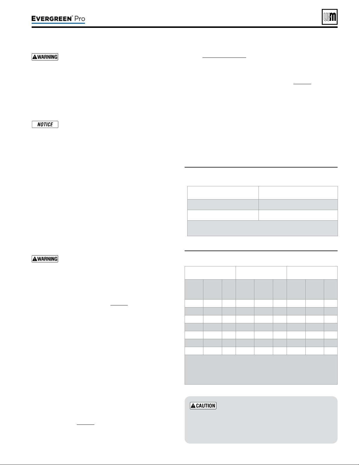
Part number 550-100-211/0122
– 39 –
220 /29 9/3 00 /39 9
Use two wrenches when tightening water piping
at boiler, using one of the wrenches to prevent
the boiler interior piping from turning. Failure to
support the boiler piping connections to prevent
them from turning could cause damage to boiler
components.
Additionalcontrols,ifrequired
e control uses temperature sensors to pro-
vide both high limit protection and modulating
temperature control. e control module also
provides low water protection by sensing the
temperature of the heat exchanger. Thecontrol’s
high limit function requires manual reset
.
Some codes/jurisdictions may require additional
external controls for high limit and/or low water
cuto protection.
Additionallimitcontrols
Following standard industry practices, if installation is to com-
ply with ASME or Canadian requirements, an additional high
temperature limit may be needed. Consult local requirements
for other codes/standards to determine if needed.
1. Install a manual reset high temperature limit constructed to
prevent a temperature setting above 200°F in system supply
piping between boiler and isolation valve. (Note that the
Control operating limit function shuts the boiler down at
195°F, or lower if set to a lower value.)
Multi-temperature systems — If the heat-
ing system includes circuits that require lower
temperature water (radiant slab circuits, for
example) as well as higher temperature circuits,
it is recommended to protect low-temperature
circuits with limit controls that are wired to a
Control external limit circuit terminals.
2. See instructions beginning on page52 for wiring informa-
tion.
3. When using a manual reset limit control or wiring in
the manual reset circuit, preferably set Max. Boiler Tem-
perature or Supply Max. at least 20°F less than the external
manual reset limit (i.e., set control no higher than 180°F
for a 200°F external limit, for example).
Separatelowwatercutoff
1. A separate low water cuto device is recommended when
the boiler is installed above piping level, and may be
required by certain state or local codes or insurance com-
panies. Consult local requirements to determine. See the
NOTICE above regarding the inherent protection provided
by the Control module. Low water cuto is standard equip-
ment with the Evergreen
®
boilers.
2. The Control’s integral protection is accepted in many
jurisdictions as meeting the requirement for low water
protection. See page56 for details.
3. When required, use a low water cuto designed for water
installations. Electrode probe-type is recommended.
See Replacement parts for the Weil-McLain low water cut-o
kit.
4. Purchase low water cuto and install in a tee in the supply pip-
ing above boiler.
5. See eld wiring instructions beginning on page52 for wiring
additional limit controls.
Backowpreventer
Use backow preventer in the cold water supply piping if required
by local codes.
(Baseboard,convectorsorcastironradiatorsONLY)
For residential space heating applications (other than radiant heat-
ing or unit heaters) ONLY, you can use the sizing suggestions in
Figure47.
Figure47 Suggested pipe sizing for boiler loop
Use at least the MINIMUM pipe size shown in
Figure47 on all boiler loop piping (connecting
boiler to and from the primary/secondary
connection). Use only primary/secondary
piping as shown.
Failure to follow these
guidelines could result in system problems.
Figure48 Pressure drop through the Evergreen
®
heat
exchanger
EVG 220 EVG299/300 EVG 399
Flow
Rate
(GPM)
Head
Loss
(ft. w.c.)
∆T
(°F)
Flow
Rate
(GPM)
Head
Loss
(ft. w.c.)
∆T
(°F)
Flow
Rate
(GPM)
Head
Loss
(ft. w.c.)
∆T
(°F)
10** 0.0 45 13** 0.0 45 18** 0.0 45
12 0.0 37 18 0.3 33 24 0.3 33
14 0.1 31 22* 0.6 27 28* 0.7 29
16 0.2 28 28 1.2 21 32 1.1 25
18* 0.2 24 32 1.7 19 36 1.6 22
20 0.3 22 – – – 40 2.2 20
22 0.5 20 – – – – – –
* Suggested design ow rates based on a 25°F (EVG
220/299/300) and 30°F (EVG 399) temp rise through the
boiler.
** Minimum ow rates.
Model Boiler loop
EVG 220 1¼” or larger
EVG 299, 300 or 399 1½” or larger
Recommendations are based on a 25°F (EVG 220/299/300)
and 30°F (EVG 399) temp rise through the boiler.

Part number 550-100-211/0122
– 40 –
All piping methods shown in this manual use
primary/secondary connection to the boiler loop.
These designs ensure proper flow through the
boiler, for the most ecient and reliable operation
of the boiler and the heating system. For other
piping methods, consult your local Weil-McLain
representative or see separate boiler piping guides.
e boiler circulator (Taco 0014 for Evergreen
®
220, 299 and
300; Taco 0013 for Evergreen
®
399) is shipped loose. Locate it
in the boiler outlet, as shown in the appropriate piping diagram
in this manual.
DONOT use the boiler circulator in any location
other than the ones shown in this manual. e
boiler circulator is selected to ensure adequate ow
through the boiler.
Failure to comply could result in unreliable perfor-
mance and nuisance shut downs from insucient ow.
Install a system circulator or zone circulators as shown in the
piping diagrams in this manual. ese circulators must be sup-
plied by the installer.
Systemorzonecirculatorowrate
1. Size circulators based on the ow rate required to achieve the
temperature change needed.
2. You can closely estimate temperature rise (or drop) through a
circuit by using the following formula, where TD is tempera-
ture rise (or drop), FLOW is ow rate (in gpm), and BTUH
is the heat load for the circuit:
FLOW =
BTUH
—–—–—–—–
TDx500
Example:
Consider a system loop for a system with total heating load equal
to 210,000 Btuh. e desired temperature drop through the sys-
tem piping is 20°F. en the required ow rate is:
FLOW =
210,000
—–—–—–—–
20x500
= 21gpm
SIMPLIFIED:
For20°temperaturedrop,FLOW=MBH/10.
Systemorzonecirculatorheadrequirement
1. e circulator must be capable of delivering the required ow
against the head loss that will occur in the piping.
2. Determine the pipe size needed and the resultant head loss
using accepted engineering methods.
3. e simplied pipe sizing here is limited to residential sys-
tems, and does not include systems with fan coil units or
radiant tubing.
The following simplified method for pipe and
circulator sizing must be limited to residential ap-
plications using baseboard (nned or cast iron),
cast iron radiators or convectors. DO NOT apply
for radiant heating, fan coil units or commercial
installations.
1. Install the boiler and piping using the recommended piping
layouts shown in this manual.
2. Size the piping and components for each circuit in the space
heating system using Figure49,page41.
Attheowrates
listed, the head loss in all piping will be 0.04 feet per
footofpipe.
a. Det
ermine the heating load (Btuh) for each circuit.
b. Calculate the ow rate for each circuit using its load.
c. To use a 20°F temperature drop, just divide the
MBH (1,000’s of Btuh) by 10.
d. Example — Flow for 20°F temp drop with 35,000 Btuh:
FLOW = 35MBH / 10 = 3.5 gpm
e. Find the pipe size in Figure49,page41 that has a max
ow rate just larger than that required for the circuit.
f. Find the total equivalent length (TEL) of the circuit.
g. TEL accounts for losses through ttings and valves by
using the equivalent length of pipe that would cause the
same head loss. Add these numbers to the measured
length of the circuit to nd TEL in feet.
h.
TELisusuallycloseto1.5timesthelengthofthe
circuitforresidentialbaseboard,radiatororcon-
vectorapplications.
i. Measure the length of each circuit from the circulator
outlet back to its inlet. en multiply this length times
1.5 to get the approximate TEL of the circuit.
j. Find the head loss for
each circuit:
TEL=1.5XCircuitLength
(feet)
HEAD=TELX0.04
(feet water column)
k. NOTE: Size system header piping for the total ow of all
connected zones.
3. Example:
a. For a circuit with heating load = 45,000 Btuh (= 45 MBH).
Measured length of circuit is 88 feet.
b. Flow = 45 MBH / 10 = 4.5 gpm.
c. TEL = 1.5 x 88 feet = 132 feet.
d. From Figure49,page41, select 1" pipe (max ow = 7.1
gpm).
e. Head loss = TEL x 0.04 = 132 x 0.04 = 5.28 feet.
f. Select a circulator that can deliver at least 4.5gpm at a
head of 5.28feet. (Read the NOTICE below.)
To use this method, limit the ow through ¾"
nned-tube baseboard to 3.9 gpm, or use 1" base-
board and limit ow to 7.1 gpm. If the total load of
the circuit requires more ow, split the circuit into
two or more.
(continued)
220 /29 9/3 00 /39 9
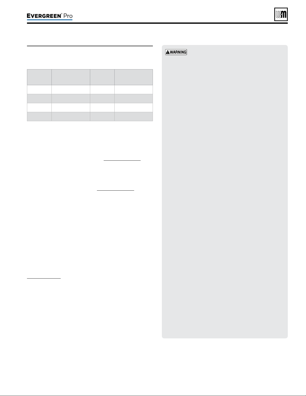
(continued)
Part number 550-100-211/0122
– 41 –
220 /29 9/3 00 /39 9
Figure49 Flow rates for 0.04 feet head loss per foot of
pipe (140°F water)
Pipe size
(inches)
MAX Flow rate (GPM)
@ 0.04 feet per foot
Pipe size
(inches)
MAX Flow rate (GPM)
@ 0.04 feet per foot
¾ 3.9 2 45
1 7.1 2½ 75
1¼ 16 3 140
1½ 24 4 290
1. Install relief valve in a reducing tee, NPT, 1½” x 1¼” x ¾” on
Evergreen
®
220 or 1½”x 1½”x ¾” on Evergreen
®
299/300/399
on the boiler supply piping tee (Figure6,page11). e
Evergreen
®
220, 299 and 300 boilers come shipped loose with
a 30 PSIG, 375 MBTU relief valve. e Evergreen
®
399 boiler
comes shipped loose with a 30 PSIG, 575 MBTU relief valve.
is boiler is capable of a pressure up to 80 PSIG. Please see
Miscellaneous parts and kits in Replacement parts for Weil-
McLain alternate pressure components.
2. If using a relief valve with a rating higher than 30 psi, other
system components may require higher pressure rated equip-
ment such as pressure gauges and expansion tank. Consult
local requirements and other codes/standards for required
equipment, if needed.
3. Pipe the relief valve only as shown, in the location shown.
4. Connect discharge piping to safe disposal location, following
guidelines in the following
WARNING.
(recommended)
Install pipe unions 1½” NPT on boiler supply and boiler return,
Figure6,page11. Installing unions in these locations will aid in
future service. Pipe unions are NOT included with the boiler.
If the boiler piping system is connected to heating coils
located in air handling units where there may be exposed to
refrigerated air circulation then it must be equipped with ow
control valves or other automatic means to prevent gravity
circulation of the boiler water during the cooling cycle.
Toavoidwaterdamageorscaldingdueto
reliefvalveoperation,asperlocalorstate
codes
:
Install relief valve ONLY with the spindle vertical,
as shown in illustrations in this manual.
Discharge line must be connected to relief valve
outlet and run to a safe place of disposal. Ter-
minate the discharge line in a manner that will
prevent possibility of severe burns or property
damage should the valve discharge. Locate away
from the top of the boiler.
Discharge line must be as short as possible and be
the same size as the valve discharge connection
throughout its entire length.
Discharge line must pitch downward from the
valve and terminate at least 6” above the oor
drain where any discharge will be clearly visible.
The discharge line shall terminate plain, not
threaded, with a material serviceable for tempera-
tures of 375 °F or greater.
Do not pipe the discharge to any place where
freezing could occur.
No shuto valve shall be installed between the
relief valve and boiler, or in the discharge line. Do
not plug or place any obstruction in the discharge
line.
Test the operation of the valve aer lling and pres-
surizing system by liing the lever. Make sure the
valve discharges freely. If the valve fails to operate
correctly, replace it with a new relief valve.
Failure to comply with the above guidelines could
result in failure of the relief valve to operate, result-
ing in possibility of severe personal injury, death
or substantial property damage.
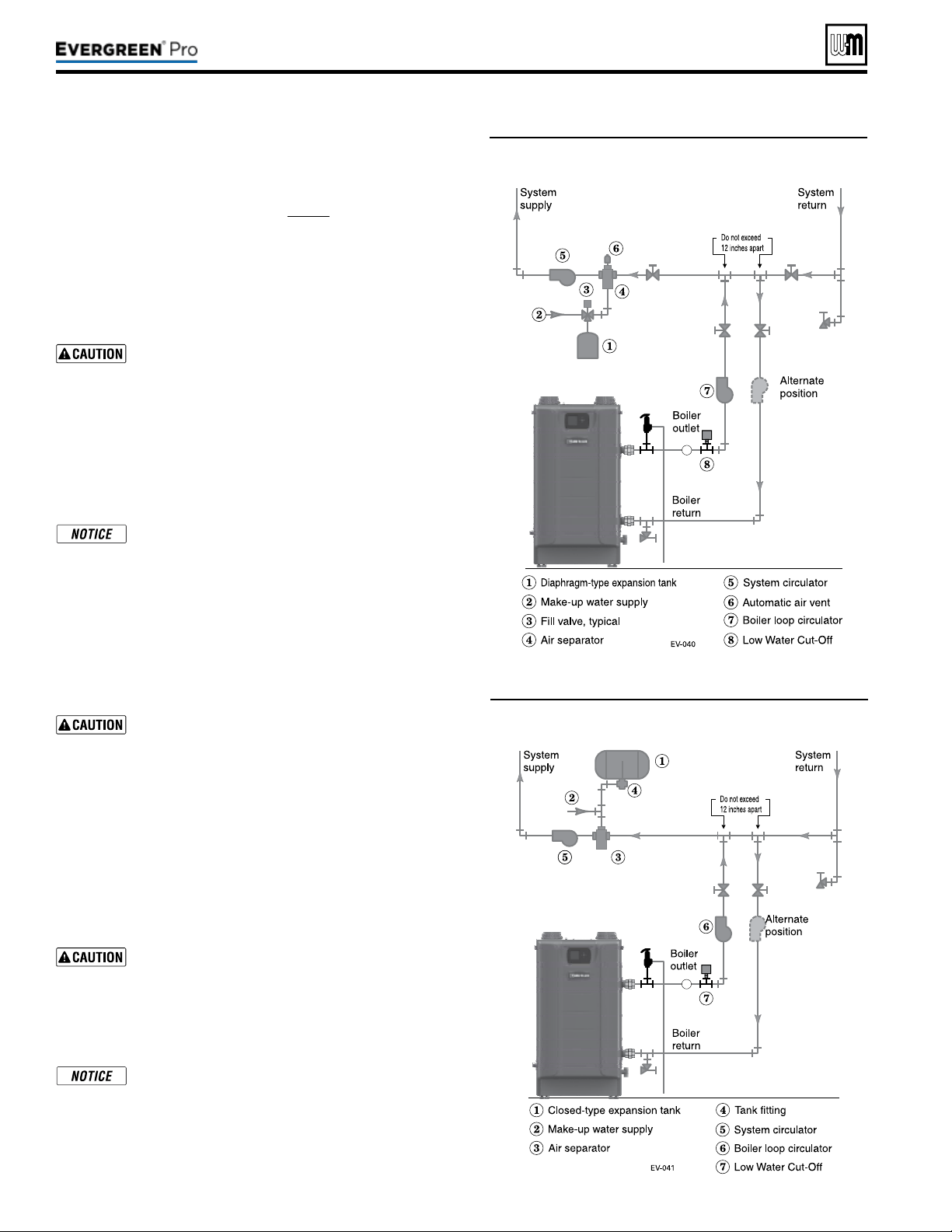
Part number 550-100-211/0122
– 42 –
Figure50 and Figure51 show typical installations of the system expansion
tank. Always locate the air separator and expansion tank as shown in the
suggested piping drawings, beginning on page43.
Ensure that the expansion tank size will handle boiler and system water
volume and temperature. Allow 4.6 gallons for
Evergreen
®
220, 7.0 gal-
lons for
Evergreen
®
299/300 and 6.7 gallons for Evergreen
®
399. See
tank manufacturer’s instructions and ratings for details. Additional tanks
may be added to the system if needed to handle the expansion. ese tanks
may be installed by connecting to tees in the system piping.
Undersized expansion tanks cause system water to
be lost from the relief valve and makeup water to be added
through the ll valve. Eventual boiler failure can result due
to excessive make-up water addition. Always locate the cold
waterllconnection at the expansion tank. Never locate
this elsewhere in the system.
Diaphragm-orbladder-typetank:
Refer to Figure50 for suggested piping when using a diaphragm- or
bladder-type expansion tank.
Diaphragm-orbladder-typeexpansiontank — Con-
trol llpressure with the tank air charge pressure. Always
check pressure and charge tank with tank removed from
system to be sure reading is accurate. Boiler relief valve is set
for 30 PSIG. Operating pressure of system, aer temperature
expansion above cold ll pressure, should not exceed 24 PSIG
to avoid weeping of relief valve.
Install an automaticairvent on top of the air separator, per separator
manufacturer’s instructions.
Closed-typeexpansiontank:
DO NOT use a closed-type tank if connecting to a water
heater that is equipped with an automatic air vent.
Figure51 shows suggested piping when using a closed-type expansion tank,
in which the air is directly in contact with tank water.
Connect piping (½” or ¾”) from the air separator top outlet to the tank
tting. Slope any horizontal piping a minimum of 1inch per 5feet of
horizontal pipe.
Always use a tanktting, such as the B&G Ta n kt ro l or Taco Taco-Trol
(shown). e tting reduces gravity ow of water in the piping to the tank,
avoids air bubbling through the tank water, and provides the proper ll
height in the tank.
Correctallleaks in the system or tank piping. Leaks allow
air to escape from the system and will cause water-logging
of the tank. is will result in water loss through the boiler
relief valve due to over-pressurization. NEVER use an
automatic air vent in a system equipped with a closed-type
expansion tank. e air removed from the system will cause
water-logging of the expansion tank.
Closed-type expansion tank — Follow tank manu-
facturer’s instructions for llingthetank. Typical tank
sizing provides for approximately 12 PSIG when the tank
is lled to the normal level and system water is cold. Note
that boiler relief valve is set for 30 PSIG. Operating pres-
sure of system, aer temperature expansion above cold ll
pressure, should not exceed 24 PSIG to avoid weeping of
relief valve.
Figure50 Piping to diaphragm (or bladder) type
expansion tank
Figure51 Piping to closed -type expansion tank
220 /29 9/3 00 /39 9
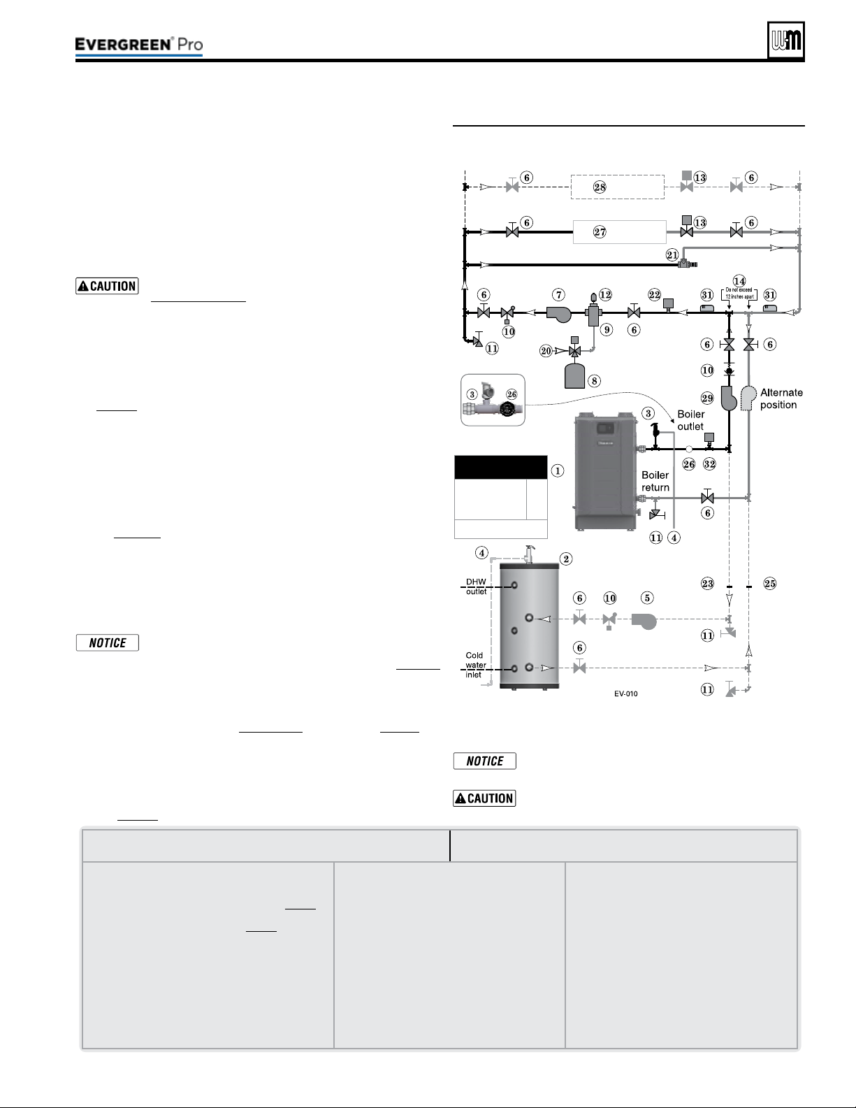
Figure52 Zone valve zoning —primary/secondary
connection — a system circulator is required
See Figure52.
is conguration is for zone valve systems using a boiler loop con-
nected as a secondary circuit o of a primary system loop.
1. Install a system circulator (supplied by installer) capable of
delivering the proper ow and head as shown.
2. e ow/check valve shown on the boiler outlet piping prevents
gravity circulation in the boiler loop during DHW heating.
Use at least the MINIMUM pipe size shown in
Figure47,page39 on all boiler loop piping (connecting
boiler to and from the primary/secondary connection,
item14). Useonlyprimary/secondarypipingas
shown. Failure to follow these guidelines could result
in system problems.
Expansion Tank required
1. Provide a system expansion tank following the guidelines on
page42.
2. DO NOT use a closed-type tank if connecting to a water heater
that is equipped with an automatic vent.
Domestic Hot Water (DHW) tank, if used
1. DHW direct connection—Pipe from the near-boiler piping to the
DHW tank’s boiler connections as shown.
2. DHW as zone— A DHW tank can be connected as a zone if a
DHW tank is NOT already connected to the boiler. See notices
on page129 to ensure compliance with the 2007 Energy Act. See
Advanced Manual to congure Boiler Pump to run during DHW
demands and change TARGET MOD SENSOR to System Supply.
3. DHW Priority operation— Using Priority 1 for DHW (default) will
turn o lower priorities during DHW calls. e MAX ON TIME
setting can be adjusted to limit how long this occurs. Use Priority
2 or 3 for DHW if DHW priority is not desired.
Overriding the Outdoor Reset function by setting control to
DHW mode when system is intended for space heating may
violate Section 303 of the 2007 Energy Act. See page129
for compliance information and exemptions.
Controlling the circulators
1. e control can control up to four circulators (boiler circulator
and three others). Refer to Field wiring, beginning on page52, for
instructions on wiring to circulators.
2. e factory default settings are: all three inputs are set up for Space
Heating (
Priority 2). Each input correlates to its respective circu-
lator output. For DHW Priority applications, wire aquastat to Input
1 and assign to Priority 1. See Field wiring instructions, beginning
on page52, for details.
LEGENDforFigure52
Note:This is a common legend for all piping diagrams.
Not all items listed appear in every gure.
1 Evergreen boiler
2 Indirect Water Heater, if used
3 Relief valve, supplied with boiler, eld piped — MUST
be piped to boiler supply connection — see page41
for information
4 Relief valve piping to drain — see page41.
5 DHW circulator
6 Isolation valves
7 System circulator
8 Expansion tank, diaphragm type, if used
9 Air separator
10 Flow/check valves or spring check
11 Purge/drain valves (one drain valve shipped loose with
boiler)
12 Auto air vent
13 Zone valves
14 Primary/secondary connection (tees no more
than 12 inches apart)
15 Expansion tank, closed type, if used (some chiller
systems may use a diaphragm-type expansion
tank)
16 Water chiller
17 Check valve
18 Y-strainer
19 Balancing valve
20 Make-up water supply – Use applicable codes to
determine if backow preventers, pressure reduc-
ing valves, and ll valves may be required
21 By-pass pressure regulator, Recommended for
zone valve systems unless other provision is made
22 High limit temperature control, when required by
local code or for a radiant system.
23 DHW tank boiler water supply connection, when
used
24 Zone circulator
25 DHW tank boiler water return connection, when
used
26 Pressure/temperature gauge, supplied with boiler,
eld piped
27 Heating circuits
28 Additional heating circuits,
29 Boiler circulator
30 Mixing device, if any
31 System supply and return sensors: Strap system
sensors to lines as shown, at least 6 pipe di-
ameters (but no more than 3 feet) from boiler
co
nnection tees.
32 Low Water Cut-o
3. For more than 3-zones, use Weil-McLain WMZV zone valve
controller.
Connect zone valve end switches to Priority 2 input.
Connect system circulator to Circ. 2 output.
Use isolation relays if connecting 3-wire zone valve
end switches to the HEAT input.
Part number 550-100-211/0122
– 43 –
220 /29 9/3 00 /39 9
MINIMUM
Boiler loop pipe size
Evergreen 220
Evergreen 299/300,
399
1¼”
1½”
See CAUTION at left.
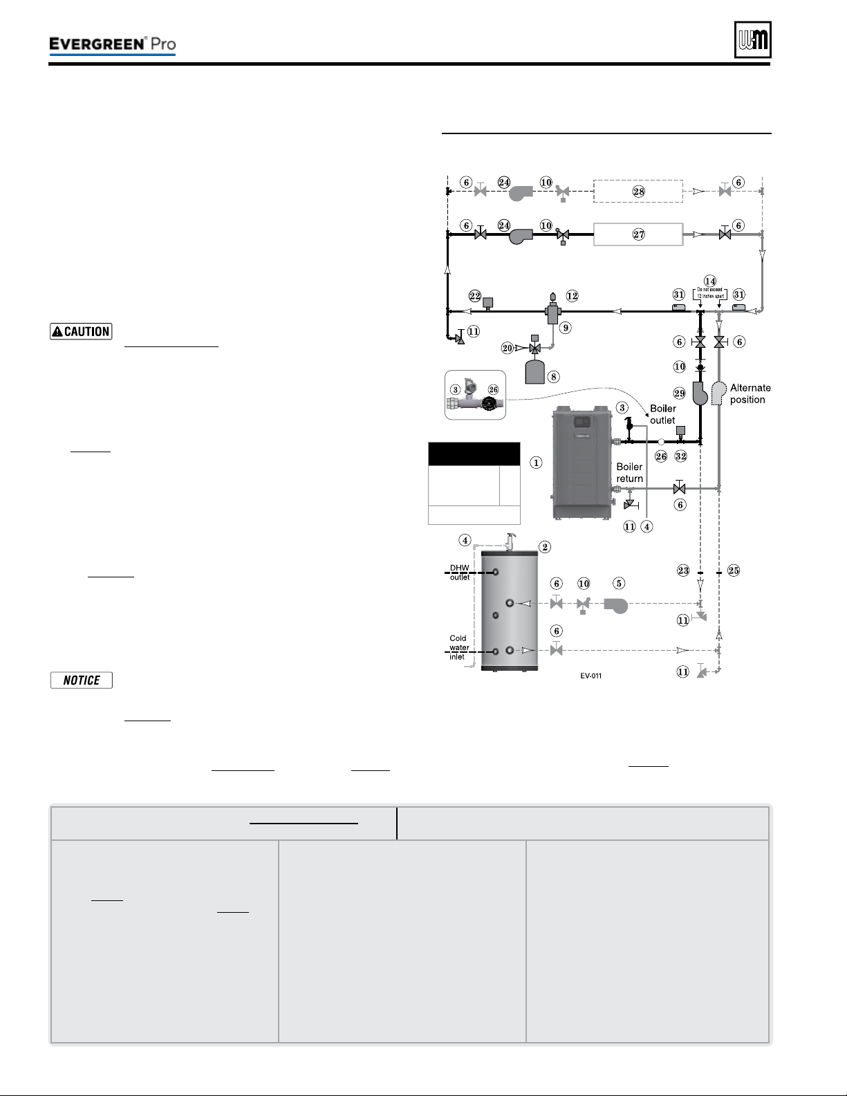
LEGENDforFigure53andFigure54,page45
Note:This is a common legend for all piping diagrams.
Not all items listed appear in every gure.
1 Evergreen boiler
2 Indirect Water Heater, if used
3 Relief valve, supplied with boiler, eld piped —
MUST be piped to boiler supply connection —
see page41 for information
4 Relief valve piping to drain — see page41.
5 DHW circulator
6 Isolation valves
7 System circulator
8 Expansion tank, diaphragm type, if used
9 Air separator
10 Flow/check valves or spring check
11 Purge/drain valves
(one drain valve shipped loose
with boiler)
12 Auto air vent
13 Zone valves
14 Primary/secondary connection (tees no more than
12 inches apart)
15 Expansion tank, closed type, if used (some chiller
systems may use a diaphragm-type expansion tank)
16 Water chiller
17 Check valve
18 Y-strainer
19 Balancing valve
20 Make-up water supply – Use applicable codes to
determine if backow preventers, pressure reducing
valves, and ll valves may be required
21 By-pass pressure regulator,
Recommended for zone
valve systems unless other provision is made
22 High limit temperature control, when required by
local code or for a radiant system.
23 DHW tank boiler water supply connection, when
used
24 Zone circulator
25 DHW tank boiler water return connection, when
used
26 Pressure/temperature gauge, supplied with boiler,
eld piped
27 Heating circuits
28 Additional heating circuits, if any
29 Boiler circulator
30 Mixing device, if any
31 System supply and return sensors: Strap system
sensors to lines as shown, at least 6 pipe diameters
(but no more than 3 feet) from boiler connection
tees.
32
Low Water Cut-o
Part number 550-100-211/0122
– 44 –
See Figure53.
1. is conguration is for circulator-zoned systems using a boiler
loop connected as a secondary circuit o of a primary system
loop. Systems zoned with circulators must pipe the boiler loop as
a secondary circuit as show.
2. Install a separate circulator (supplied by installer) for each zone
capable of delivering the proper ow and head as shown.
3. e ow/check valve shown on the boiler outlet piping prevents
gravity circulation in the boiler loop during DHW heating.
Use at least the MINIMUM pipe size shown in
Figure47,page39 on all boiler loop piping (connecting
boiler to and from the primary/secondary connection,
item14). Useonlyprimary/secondarypipingas
shown. Failure to follow these guidelines could result
in system problems.
Expansion Tank required
1. Provide a system expansion tank following the guidelines on
page42.
2. DO NOT use a closed-type tank if connecting to a water heater
that is equipped with an automatic vent.
Domestic Hot Water (DHW) tank, if used
1. DHW direct connection—Pipe from the near-boiler piping to the
DHW tank’s boiler connections as shown.
2. DHW as zone— A DHW tank can be connected as a zone if a
DHW tank is NOT already connected to the boiler. See notices
on page129 to ensure compliance with the 2007 Energy Act. See
Advanced Manual to congure Boiler Pump to run during DHW
demands and change TARGET MOD SENSOR to System Supply.
3. DHW Priority operation— Using Priority 1 for DHW (default) will
turn o lower priorities during DHW calls. e MAX ON TIME
setting can be adjusted to limit how long this occurs. Use Priority
2 or 3 for DHW if DHW priority is not desired.
Overriding the Outdoor Reset function by setting control
to DHW mode when system is intended for space heat-
ing may violate Section 303 of the 2007 Energy Act. See
page129 for compliance information and exemptions.
Controlling the circulators
1. e control can control up to four circulators (boiler circulator
and three others). Refer to Field wiring, beginning on page52, for
instructions on wiring to circulators.
Figure53 Circulator zoning plus optional DHW piping
2. e factory default settings are: all three inputs are set up
for Space Heating (
Priority 2). Each input correlates to its
respective circulator output. For DHW Priority applications,
wire aquastat to Input 1 and assign to Priority 1. See Field wir-
ing instructions, beginning on page52, for details.
3. For more than 3-zones, use Weil-McLain WMCR zone Circ
controller.
(continued)
220 /29 9/3 00 /39 9
MINIMUM
Boiler loop pipe size
Evergreen 220
Evergreen 299/300,
399
1¼”
1½”
See CAUTION at left.
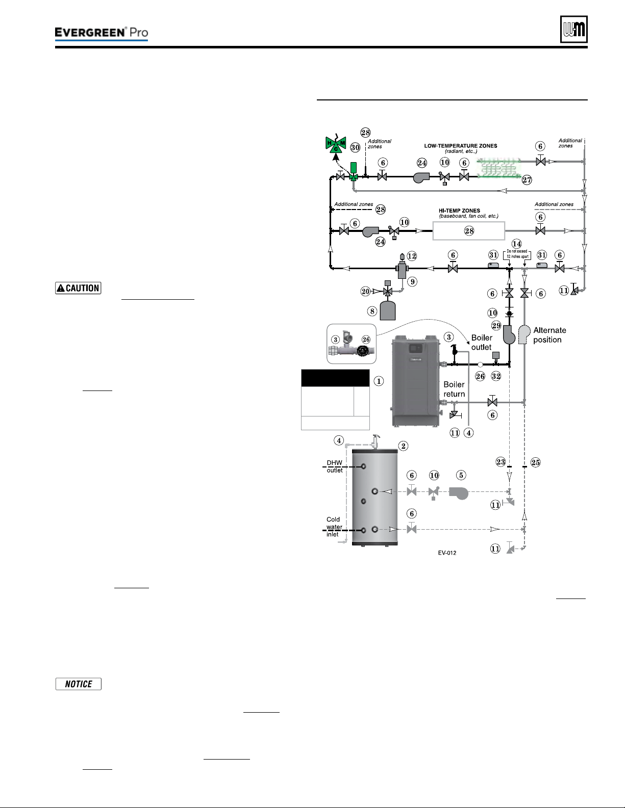
Part number 550-100-211/0122
– 45 –
220 /29 9/3 00 /39 9
Figure54 Circulator zoning with high- and low-temperature
heating zones
See Figure54.
1. is conguration is for circulator-zoned systems with
high- and low-temperature heating zones using a boiler
loop connected as a secondary circuit o of a primary
system loop. Systems zoned with circulators must pipe
the boiler loop as a secondary circuit as shown.
2. Install a separate circulator (supplied by installer) for
each zone capable of delivering the proper ow and
head as shown.
3. e ow/check valve shown on the boiler outlet piping
prevents gravity circulation in the boiler loop during DHW
heating.
Use at least the MINIMUM pipe size shown
in Figure47,page39 on all boiler loop piping
(connecting boiler to and from the primary/
secondary connection, item14). Useonlypri-
mary/secondarypipingasshown. Failure
to follow these guidelines could result in system
problems.
Expansion Tank required
1. Provide a system expansion tank following the guidelines
on page42.
2. DO NOT use a closed-type tank if connecting to a water
heater that is equipped with an automatic vent.
System setup and settings
1. Hi-temp emitters may be baseboards, radiators, fan coils,
or heat exchangers.
2. Add a mixing device (Figure54, item 30) to help ensure
supply water temperature will not exceed the maximum
allowable for the radiant system.
3. Heating zone supply water temperature settings should
be selected for the hi-temp zones. e mixing device
regulates supply temperature to the lower-temp zones.
Domestic Hot Water (DHW) tank, if used
1. DHW direct connection—Pipe from the near-boiler piping
to the DHW tank’s boiler connections as shown.
2. DHW as zone— A DHW tank can be connected as a zone
if a DHW tank is NOT already connected to the boiler. See
notices on page129 to ensure compliance with the 2007
Energy Act. See Advanced Manual to congure Boiler Pump
to run during DHW demands and change TARGET MOD
SENSOR to System Supply.
3. DHW Priority operation— Using Priority 1 for DHW
(default) will turn o lower priorities during DHW calls.
e MAX ON TIME setting can be adjusted to limit how
long this occurs. Use Priority 2 or 3 for DHW if DHW
priority is not desired.
Overriding the Outdoor Reset function by
setting control to DHW mode when system is
intended for space heating may violate Section
303 of the 2007 Energy Act. See page129 for
compliance information and exemptions.
Controlling the circulators
1. e Control can control up to four circulators (boiler cir-
culator and three others). Refer to Field wiring, beginning
on page52, for instructions on wiring to circulators.
2. e factory default settings are: all three inputs are set up for Space
Heating (
Priority 2). Each input correlates to its respective circulator
output. For DHW Priority applications, wire aquastat to Input 1 and as-
sign to Priority 1. See Field wiring instructions, beginning on page52,
for details.
3. For more than 3-zones, use Weil-McLain WMCR zone Circ
controller.
4. e Control can operate the Hi-Temp Zones and Low-Temp Zones
at the same time when the corresponding inputs are set to the same
priority (default: Priority 2). A mixing device must be used in this ap-
plication to guarantee the proper temperature to the Low-Temp Zones.
Two dierent Priorities can also be used in this application (such as
Priority 2 and Priority 3). One priority used for the Hi-Temp Zones
and the other used for the Low-Temp Zones. is will allow the boiler
to run at lower temperatures while satisfying the Low-Temp Zones
thus increasing the boilers eciency. Proper safety measures should
be takes to ensure safe water temperatures to the Low-Temp Zones
such as a Mixing device and/or a High Limit Temperature Control.
e Control can only satisfy one priority at a time. Please set min and
max on timers for each priority for optimal performance.
(continued)
MINIMUM
Boiler loop pipe size
Evergreen 220
Evergreen 299/300,
399
1¼”
1½”
See CAUTION at left.
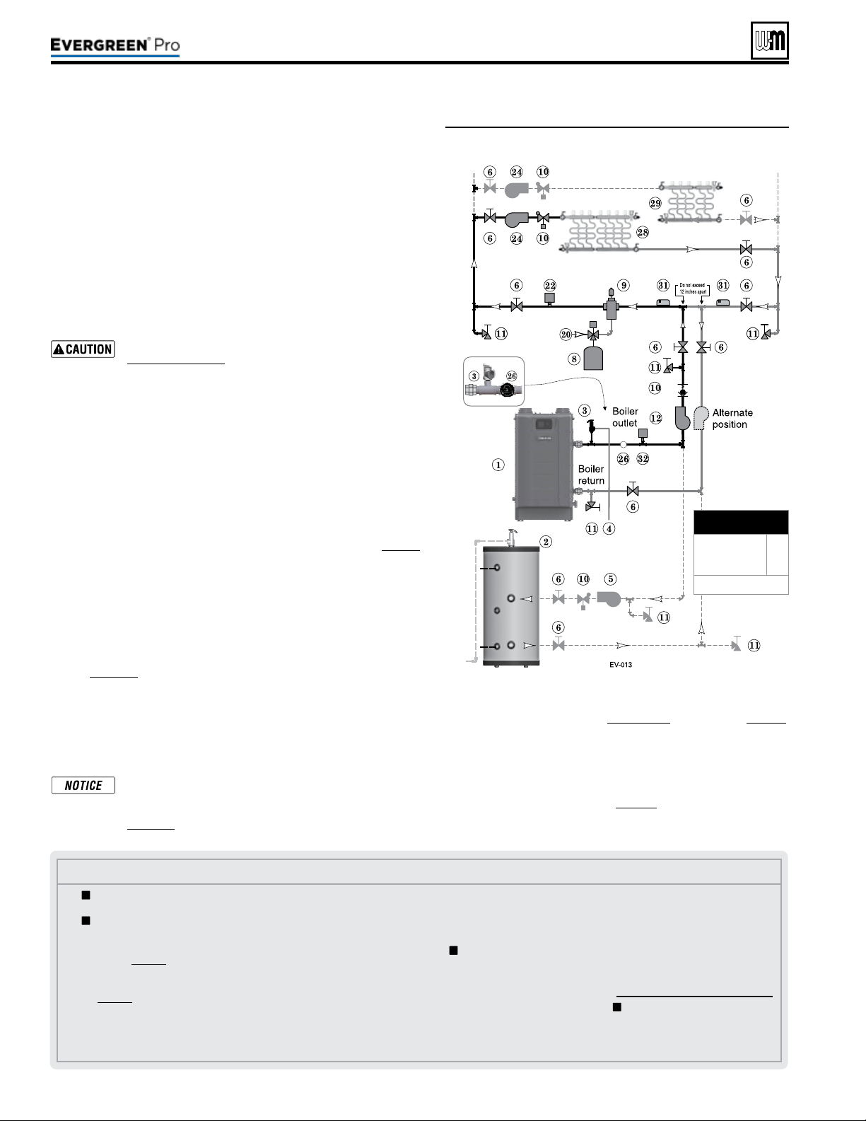
Part number 550-100-211/0122
– 46 –
Figure55 Typical radiant heating system piping —
circulator zoning
Legend—Figure55
1 Evergreen boiler
2 Indirect water heater, if used
3 Relief valve, supplied with
boiler, eld piped — MUST be
piped to boiler supply connec-
tion — see page41 for informa-
tion.
4 Relief valve piping to drain —
see page41.
5 DHW circulator.
6 Isolation valves.
8 Supplementary expansion tank,
diaphragm type, if used.
9 Air separator.
10 Flow/check valves or spring
check.
11 Purge/drain valves (one drain
valve is supplied loose with the
boiler).
12 Boiler circulator.
14 Primary/secondary connection
(tees no more than 12 inches
apart)
20 Make-up water supply.
22 High limit temperature control,
when required by local code or
for a radiant system.
23 Backow preventer, if used.
24 Zone circulators.
25 Pressure reducing valve, if used.
26
Pressure/temperature gauge,
supplied with boiler, eld
piped.
27 Quick-ll valve, if used.
28 Heating circuits.
29 Additional heating circuits, if
any.
30 Mixing device, if any
31 System supply and return sen-
sors: Strap system sensors to
lines as shown, at least 6 pipe
diameters (but no more than
3 feet) from boiler connection
tees.
32 Low Water Cut-o
= Items supplied with boiler
— all other items supplied by
installer.
See Figure55.
1. e Evergreen
®
boiler is ideal for use in radiant heating. e unique
heat exchanger design allows it to work well even in condensing
mode. ere is no need to regulate boiler return water temperature
in radiant heating applications.
2. Apply this conguration for typical radiant heating applications.
3. Size the system piping and circulators to provide the ow and pres-
sure drop needed.
4. e ow/check valve shown on the boiler outlet piping prevents
gravity circulation in the boiler loop during DHW heating.
Use at least the MINIMUM pipe size shown in
Figure47,page39 on all boiler loop piping (connecting
boiler to and from the primary/secondary connection).
Useonlyprimary/secondarypipingasshown.
Failure to follow these guidelines could result in system
problems.
Highlimitinsystempiping
1. Add the recommended high limit control (Figure55, item22) to help
ensure supply water temperature will not exceed the maximum allow-
able for the radiant system.
2. Wire the limit control to either the manual reset or automatic reset
external limit circuit of the Control.
Expansion Tank required
1. Provide a system expansion tank following the guidelines on page42.
2. DO NOT use a closed-type tank if connecting to a water heater that is
equipped with an automatic vent.
Domestic Hot Water (DHW) tank, if used
1. DHW direct connection—Pipe from the near-boiler piping to the
DHW tank’s boiler connections as shown.
2. DHW as zone— A DHW tank can be connected as a zone if a
DHW tank is NOT already connected to the boiler. See notices
on page129 to ensure compliance with the 2007 Energy Act. See
Advanced Manual to congure Boiler Pump to run during DHW
demands and change TARGET MOD SENSOR to System Supply.
3. DHW Priority operation— Using Priority 1 for DHW (default) will
turn o lower priorities during DHW calls. e MAX ON TIME
setting can be adjusted to limit how long this occurs. Use Priority
2 or 3 for DHW if DHW priority is not desired.
Overriding the Outdoor Reset function by setting control
to DHW mode when system is intended for space heating
may violate Section 303 of the 2007 Energy Act. See
page129 for compliance information and exemptions.
Controlling the circulators
1. e control can control up to four circulators (boiler circulator
and three others). Refer to Field wiring, beginning on page52,
for instructions on wiring to circulators.
2. e factory default settings are: all three inputs are set up
for Space Heating (
Priority 2). Each input correlates to its
respective circulator output. For DHW Priority applications,
wire aquastat to Input 1 and assign to Priority 1. See Field wiring
instructions, beginning on page52, for details.
3. For more than 3-zones, use Weil-McLain WMCR zone Circ
controller.
(continued)
220 /29 9/3 00 /39 9
MINIMUM
Boiler loop pipe size
Evergreen 220
Evergreen 299/300,
399
1¼”
1½”
See CAUTION at left.
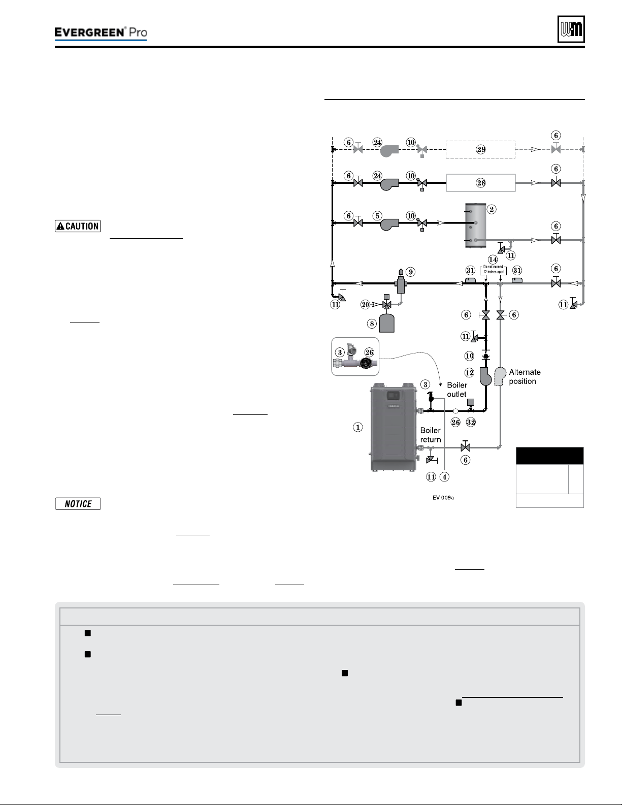
Part number 550-100-211/0122
– 47 –
220 /29 9/3 00 /39 9
See Figure56.
1. is conguration is for circulator-zoned systems with a
DHW tank piped as a zone in the system. e boiler is con-
nected as a secondary circuit o of a primary system loop.
Systems zoned with circulators must pipe the boiler loop as
a secondary circuit as shown.
2. Install a separate circulator (supplied by installer) for each
zone capable of delivering the proper ow and head as
shown.
Use at least the MINIMUM pipe size shown in
Figure47,page39 on all boiler loop piping (con-
necting boiler to and from the primary/second-
ary connection, item14). Use only primary/
secondarypipingasshown. Failure to follow
these guidelines could result in system problems.
Expansion Tank required
1. Provide a system expansion tank following the guidelines on
page42.
2. DO NOT use a closed-type tank if connecting to a water heater
that is equipped with an automatic vent.
Domestic Hot Water (DHW) tank, as shown
1. Install the DHW tank as a system zone. e DHW tank can
be piped as a zone ONLY if a DHW tank is NOT connected to
the boiler directly.
2. Wire the DHW aquastat and circulator to an input/output pair,
normally Input/Output 1. See notices on page129 to ensure
compliance with the 2007 Energy Act. See the Advanced
Manual to congure Boiler Pump to run during DHW demands
and change TARGET MOD SENSOR to System Supply.
3. DHW Priority operation— Using Priority 1 for DHW (default)
will turn o lower priorities during DHW calls. e MAX ON
TIME setting can be adjusted to limit how long this occurs.
Use Priority 2 or 3 for DHW if DHW priority is not desired.
Overriding the Outdoor Reset function by setting
control to DHW mode when system is intended for
space heating may violate Section 303 of the 2007
Energy Act. See page129 for compliance informa-
tion and exemptions.
Controlling the circulators
1. e control can control up to four circulators (boiler circulator
and three others). Refer to Field wiring, beginning on page52,
for instructions on wiring to circulators.
Figure56 Circulator zoning with DHW as a zone
Legend—Figure56
1 Evergreen boiler
2 Indirect water heater, if used
3 Relief valve, supplied with
boiler, eld piped — MUST
be piped to boiler supply
connection — see page37 for
information.
4 Relief valve piping to drain —
see page41.
5 DHW circulator.
6 Isolation valves.
8 Supplementary expansion
tank, diaphragm type, if used.
9 Air separator.
10 Flow/check valves or spring check.
11 Purge/drain valves (one drain
valve is supplied loose with the
boiler).
12 Boiler circulator.
14 Primary/secondary connection
(tees no more than 12 inches
apart)
20 Make-up water supply.
22 High limit temperature control,
when required by local code or
for a radiant system.
23 Backow preventer, if used.
24 Zone circulators.
25 Pressure reducing valve, if
used.
26
Pressure/temperature
gauge, supplied with boiler,
eld piped.
27 Quick-ll valve, if used.
28 Heating circuits.
29 Additional heating circuits, if
any.
31 System supply and return sen-
sors: Strap system sensors to
lines as shown, at least 6 pipe
diameters (but no more than
3 feet) from boiler connec-
tion tees.
32 Low Water Cut-o
= Items supplied with boiler
— all other items supplied by
installer.
2. e factory default settings are: all three inputs are set up
for Space Heating (
Priority 2). Each input correlates to its
respective circulator output. For DHW Priority applications,
wire aquastat to Input 1 and assign to Priority 1. See Field wiring
instructions, beginning on page52, for details.
3. For more than 3-zones, use Weil-McLain WMCR zone
Circ controller. See EVG Advanced Manual for proper wiring.
(continued)
MINIMUM
Boiler loop pipe size
Evergreen 220
Evergreen 299/300,
399
1¼”
1½”
See CAUTION at left.
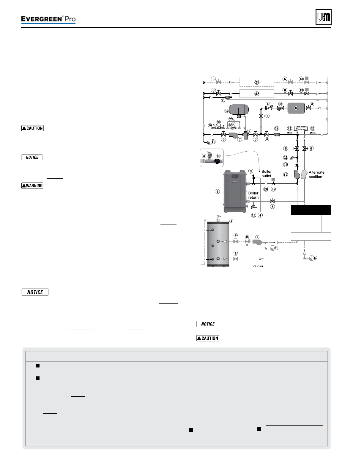
Part number 550-100-211/0122
– 48 –
Figure57 Chilled water system plus optional DHW
piping
See Figure57.
1. e chiller must be piped in parallel with the boiler.
2. Use appropriate valves to prevent chilled medium from entering boiler.
3. Circulator zoning option — e space heating system can be zoned with
circulators if a separate circulator is supplied for the chilled water loop.
Install a separate circulator for each zone.
4. e ow/check valve shown on the boiler outlet piping prevents gravity
circulation in the boiler loop during DHW heating.
Use at least the MINIMUM pipe size shown in Figure47,page39 on
all boiler loop piping (connecting boiler to and from the prima-
ry/secondary connection). Use only primary/secondary piping as
shown. Failure to follow these guidelines could result in system
problems.
If antifreeze is used in the system, consider the eects of antifreeze
on circulator sizing and DHW performance. Some local codes
may require double-wall DHW heat exchanger design. Use only
the antifreeze listed by Weil-McLain for use with this boiler. See
page86 for details.
Chilled medium, if used, is piped in parallel with heating boiler
as shown in Figure57. Use appropriate valves to prevent chilled
medium from entering boiler. If boiler is connected to heating
coils located in air handling units where they can be exposed to
refrigerated air, use ow control valves or other automatic means
to prevent gravity circulation during cooling cycle.
Expansion Tank required
1. Provide a system expansion tank following the guidelines on page42.
2. DO NOT use a closed-type tank if connecting to a water heater that is
equipped with an automatic vent.
Domestic Hot Water (DHW) tank, if used
1. DHW direct connection—Pipe from the near-boiler piping to the DHW
tank’s boiler connections as shown.
2. DHW as zone—Not recommended for this application.
3. DHW Priority operation— Using Priority 1 for DHW (default) will
turn o lower priorities during DHW calls. e MAX ON TIME set-
ting can be adjusted to limit how long this occurs. Use Priority 2 or 3
for DHW if DHW priority is not desired.
Overriding the Outdoor Reset function by setting control to
DHW mode when system is intended for space heating may
violate Section 303 of the 2007 Energy Act. See page129 for
compliance information and exemptions.
Controlling the circulators
1. e control can control up to four circulators (boiler circulator and three
others). Refer to Field wiring, beginning on page52, for instructions on
wiring to circulators.
Use isolation relays if connected 3-wire zone valve end
switches to the Heat inputs.
Connect zone valve end switches to Priority2 input.
Connect system circulator to CIRC 2 output.
2. e factory default settings are: all three inputs are setup for
Space Heating (Priority 2). Each input correlates to its respec-
tive circulator output. F
or DHW Priority applications, wire
aquastat to Input 1 and assign to Priority 1.
See Field wiring
instructions, beginning on page52, for details.
3. For more than 3-zones, use Weil-McLain WMZV zone valve
controller.
(continued)
Legend—Figure57
1 Evergreen boiler
2 Indirect water heater, if used
3 Relief valve, supplied with
boiler, eld piped — MUST
be piped to boiler supply
connection — see page41 for
information.
4 Relief valve piping to drain —
see page41.
5 DHW circulator.
6 Isolation valves.
7 System circulator.
9 Air separator.
10 Flow/check valves or spring check.
11 Purge/drain valves (one drain
valve is supplied loose with the
boiler).
12 Boiler circulator.
13 Zone valves.
14 Primary/secondary connection
(tees no more than 12 inches apart)
15 Supplementary expansion tank,
closed type, REQUIRED for
chiller systems (some chiller
systems may use a diaphragm
type expansion tank).
16 Water chiller.
17 Check valve.
18 Y-strainer.
19 Balancing valve.
20 Make-up water supply.
21 By-pass pressure regulator,
RECOMMENDED for zone
valve systems unless other
provision is made.
23 Backow preventer, if used.
25 Pressure reducing valve, if
used.
26
Pressure/temperature gauge,
supplied with boiler, eld piped.
27 Quick-ll valve, if used.
28 Heating circuits.
29 Additional heating circuits, if
any.
31 System supply and return sen-
sors: Strap system sensors to
lines as shown, at least 6 pipe
diameters (but no more than
3 feet) from boiler connection
tees.
32 Low Water Cut-o
= Items supplied with boiler
— all other items supplied by
installer.
220 /29 9/3 00 /39 9
MINIMUM
Boiler loop pipe size
Evergreen 220
Evergreen 299/300,
399
1¼”
1½”
See CAUTION at left.
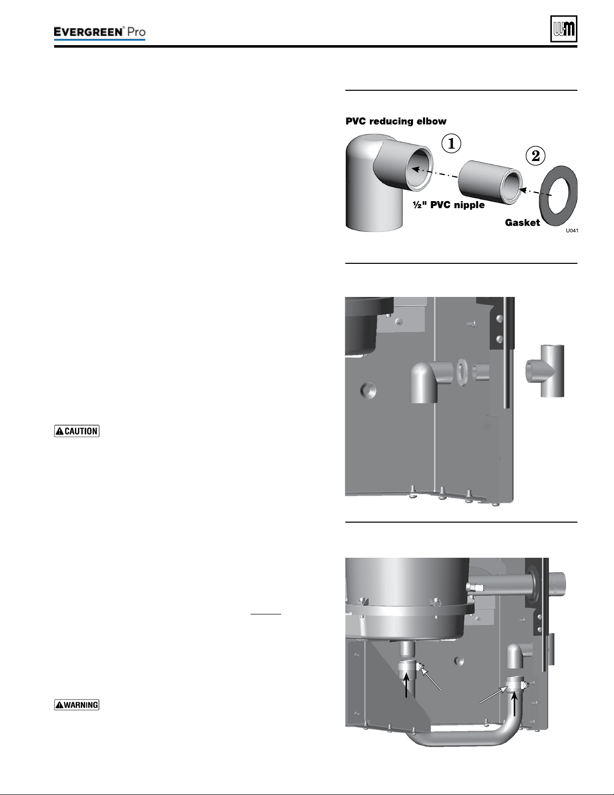
Part number 550-100-211/0122
– 49 –
220 /29 9/3 00 /39 9
Figure58 Condensate trap assembly
Figure59 Condensate trap assembled into jacket
1. Remove PVC ttings and gasket from the accessories bag.
2. Deburr and chamfer outside and inside of ½” PVC nipple to ensure
even cement distribution when joining.
3. Clean nipple ends and all ttings. Dry thoroughly.
4. For each joint in the condensate line, apply the following.
Assemble parts ONLY in the order given (See Figure58).
a. Apply primer liberally to both joint surfaces — pipe end and
tting socket.
b. While primer is still damp, lightly apply approved cement to
both surfaces in a uniform coating.
c. Apply a second coat of cement to both surfaces. Avoid using
too much cement on sockets to prevent cement buildup inside.
d. With cement still wet, insert pipe into tting, twisting ¼ turn.
Make sure pipe is fully inserted.
e. Wipe excess cement from joint. Check joint to be sure a
smooth bead of cement shows around the entire joint.
5. Assemble the ½” PVC nipple to the PVC reducing elbow as shown.
6. Allow joint to dry completely.
7. en slide gasket over nipple as shown in Figure59.
8. Slide nipple through jacket condensate line hole to position as
shown in Figure59.
9. Cement the ½” tee to the protruding ½” nipple. Be sure both
nipple and reducing elbow nish upright.
Firmly press the reducing elbow and the tee together
while the cement sets to ensure the gasket is securely
compressed. e gasket ensures the jacket enclosure is
airtight at this location.
1. Remove condensate trap line from bag.
2. Connecting condensate line assembly — Figure60:
a. Place a hose clamp over the end of the condensate line.
b. en slide the end of the trap line over the heat exchanger
condensate connection.
c. Tighten the hose clamp to secure the trap line.
d. See “Fill Condensate trap with water” on page88 for proper
instructions on priming the condensate trap, if applicable at
the time.
e. Place a hose clamp over the other end of the condensate trap
line.
f. Slide the trap line over the reducing elbow and secure with
the hose clamp.
Nothing is to be added to top of this tee, Figure59.
Figure60 Condensate drain line connections
Hose
clamps
See
Warning.
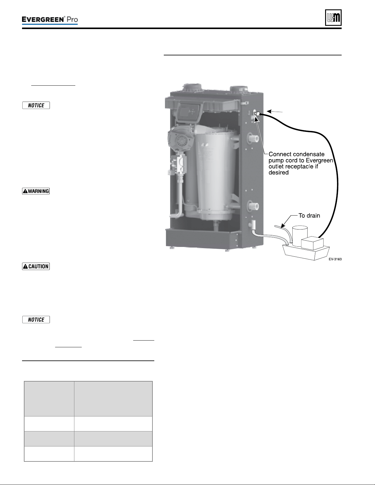
Part number 550-100-211/0122
– 50 –
(continued)
1. Connect condensate drain tubing to the ½” PVC
tee and run to oor drain or condensate pump (see
Figure62,page50). Use ½” PVC or CPVC pipe; or
5/8” I. D. tubing (Installer supplied).
Use materials approved by the author-
ity having jurisdiction. In the absence
of other authority, PVC and CPVC pipe
must comply with ASTM D1785, F441 or
D2665. Cement and primer must comply
with ASTM D2564, F656, or F493. For
Canada, use CSA or ULC certied PVC
or CPVC pipe, ttings and cement.
2. Leave the top of the ½” tee OPEN. is is needed as
a vacuum break. Do not install any pipe or tting
into top of tee.
Nothing is to be added to top of this tee.
3. When installing a condensate pump, select one
approved for use with condensing boilers and fur-
naces. e pump should have an overow switch to
prevent property damage from condensate spillage.
See Figure61 for required ow capacity.
4. When sizing condensate pumps, make sure to
include the total load of all Evergreen
®
boilers con-
nected to it.
e condensate line must remain unob-
structed, allowing free ow of condensate.
If condensate is allowed to freeze in the
line or if the line is obstructed in any
other manor, condensate can exit from
the boiler tee, resulting in potential water
damage to property.
Condensate from the Evergreen
®
boiler
will be slightly acidic (typically with a pH
from 3.2 to 4.5). Install a neutralizing lter
if required by local codes. See Replace-
ment parts at the end of this manual for
the Weil-McLain kit.
Boiler
Minimumrecommended
condensatepump
capacity,perboiler,
GPH
EVG 220 6
EVG 299/300 8
EVG 399 10
Figure61 Suggested condensate pump
capacity, GPH
Figure62 Condensate pump (by others), typical
220 /29 9/3 00 /39 9
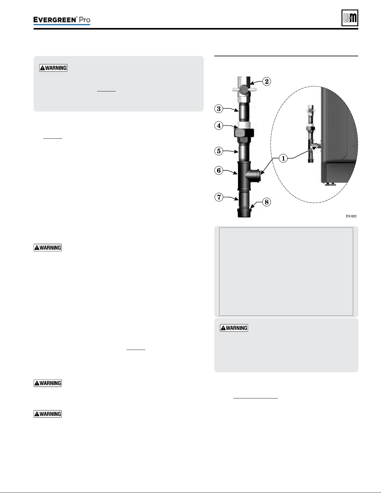
Figure63 Connect gas supply piping
Part number 550-100-211/0122
– 51 –
220 /29 9/3 00 /39 9
1 Boiler gas supply connection, ¾”NPT male.
2 T-handle gas cock, ¾” NPT, shipped loose with
boiler.
ALLOFTHEFOLLOWINGARESUPPLIEDBYTHE
INSTALLER:
3 Nipple, ¾” NPT
4 Union, ¾” NPT
5 Nipple, ¾” NPT
6 Tee, ¾” NPT
7 Nipple, ¾” NPT x 4”, for drip leg
8 Cap, ¾” NPT
Evergreen
®
boilers are shipped ready to fire
natural gas ONLY. You must install the propane
venturi kit if the boiler will be connected to pro-
pane. See page12. Failure to comply could result in
severe personal injury, death or substantial property
damage.
Gaspipesizing
See page18 for gas line sizing information.
1. Refer to Figure63 to pipe gas to boiler.
a. Place a wrench on the gas line when tightening the gas line
assembly to the boiler gas connection (item1).
b. Install steel pipe ttings and factory-supplied gas cock as shown
in Figure63. All pipe ttings are supplied by the installer. e
gas cock is shipped loose with the boiler.
c. In Canada — e gas shut-o valve (item2) must be identied
by the installer.
2. Use pipe dope compatible with propane gases. Apply sparingly
only to male threads of pipe joints so that pipe dope does not
block gas ow.
Failure to apply pipe dope as detailed above can result
in severe personal injury, death or substantial property
damage.
3. Connect gas supply piping to the 3/4” NPT gas cock (item2).
4. Support gas piping with hangers, not by boiler or its accessories.
5. Purge all air from gas supply piping.
6. Before placing boiler in operation, check boiler and its gas con-
nection for leaks.
a. During any pressure testing at less than 14” (356mm) w.c.,
close the gas shuto valve and disconnect system gas piping.
At higher test pressures, disconnect boiler and gas valve from
gas supply piping.
b. Aer placing the boiler in operation, the ignition system safety
shuto device must be tested, page91.
7. Install 100% lockup gas pressure regulator in supply line if inlet
pressure can exceed 14” (356mm) w.c. at any time. Adjust lockup
regulator for 14” (356mm) w.c. maximum.
Do not check for gas leaks with an open ame — use
bubble test. Failure to use bubble test or check for gas
leaks can cause severe personal injury, death or substan-
tial property damage.
DO NOT adjust or attempt to measure gas valve outlet
pressure. e gas valve is factory-set for the correct out-
let pressure. is setting is suitable for natural gas and
propane. Attempting to alter or measure the gas valve
outlet pressure could result in damage to the valve, caus-
ing potential severe personal injury, death or substantial
property damage.
Checkgaspressureatinlettoboiler
1. See Figure88,page91 for location of the gas inlet pres-
sure test port.
2. For natural gas or propane, the pressure required at gas
valve inlet pressure port (verify minimum gas pressure
when all gas appliances are in operation):
a. Maximum: 14” (356mm) w.c. with no ow
(lockup) or with boiler on.
b. Minimum gas pressure, with gas owing (verify
during boiler startup, while boiler is at high re)
3½” (89mm) w.c.
Usetwowrenches when tightening gas
piping at boiler, using one wrench to pre-
vent the boiler gas line connection from
turning. Failure to support the boiler gas
connection pipe to prevent it from turn-
ing could damage gas line components.
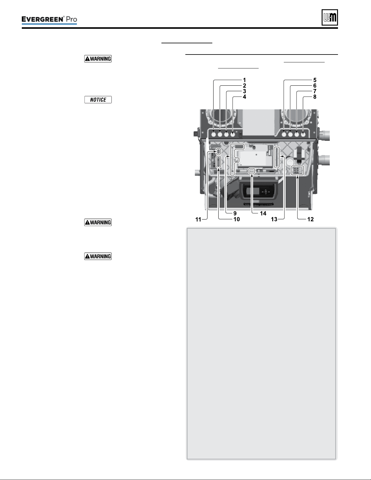
(see wiring diagram, Figure 65, page 59)
Part number 550-100-211/0122
– 52 –
Figure64 Field wiring overview (see Figure 65, page 59 and
Figure 66, page 60 for detailed schematic and ladder
wiring diagrams)
ELECTRICALSHOCK HAZARD — For your safety, turn o
electrical power supply at service entrance panel before making
any electrical connections to avoid possible electric shock hazard.
Failure to do so can cause severe personal injury or death.
e installation must comply with National Electrical Code and
any other national, state, provincial or local codes or regulations.
In Canada, CSA C22.1 Canadian Electrical Code Part 1, and any
local codes.
Wiring must be N.E.C. Class 1. If original wiring as supplied with
boiler must be replaced, use only type 105 °C wire or equivalent.
Boiler must be electrically grounded as required by National
Electrical Code ANSI/NFPA 70 – latest edition.
Do not use 24V from transformer to power any external devices
that are not listed in this manual.
Eight knockouts are provided in the top of the cabinet for line
and low voltage wiring. See Figure64 for locations and functions.
InstallerMUSTuseastrainrelief through jacket knockouts.
Failure to do so can cause severe personal injury, death or sub-
stantial property damage.
InstallerMUSTSEAL all electrical entrances using a sealed strain
relief or a strain relief sealed with duct seal putty or silicone.
Sealing the entrances prevents water from entering the electrical
enclosure. Failure to seal entrances could result in severe personal
injury, death or substantial property damage.
See details on the following pages for the wiring connections
outlined below:
Requiredwiringconnections
y 120VAC power to boiler; 120VAC power out to boiler cir-
culator; system supply and return temperature sensors; and
outdoor temperature sensor (unless exempt as described in
this manual).
Connectionsasneededbysystems
y ermostat, end switch or other inputs for call for heat.
y System zone circulators, valves, relays, etc.
y System circulator, when required.
y Low water cut-o (when required).
Optionalwiringconnections
y External limits; proof-of-closure interlocks (combustion air
damper, ow switch, etc.); 0–10VDC for target or modulation
control; remote alarm; additional heat demand contact; and
communication cables for boiler networking and/or building
management system interface (MODBUS).
1 120VAC knockout for power to boiler circulator terminals at
item11.
2 For wiring to P12 – Low water cuto kit (when used) wire
harness should be routed through this knockout with no
other wires. Provide strain relief and a seal at cabinet entry.
3&4 Two knockouts for low voltage wires to terminal strips at
items9 and 10 (terminal strips P10, P11, P13, P14, P15 and
P16). ese knockouts are provided with multi-hole cord
grips. Use if allowed by codes.
• ermostat, aquastat, limit device, outdoor temperature
sensor, system temperature sensor, and boiler communica-
tion wiring should be mounted through the cord grip.
• Mount cord grip to desired low voltage knockout and
secure with a locknut before passing wire through cord grip.
• Aer all wires are routed through cord grip holes and
secured to connecting terminals, hand tighten the nut on top
of the cord grip to seal any unused holes and grip the wires
tightly.
5,6,7&8 Four knockouts for 120VAC wiring to power in (at
item12) and three 120VAC outputs on terminal strip (at
item13).
9 Low voltage connection terminal strips are shipped loose
with boiler and must be plugged into receptacles on control
module.
10 Low voltage terminal strips (P4 & P5) for connection of com-
munication cables (multiple boiler applications).
11 120VAC terminal strip (P8) on Pump/Comm Board for
boiler circulator power.
12 120VAC terminal strip (T1) for boiler power supply (15-amp
breaker unless larger capacity is required for outputs con-
nected on terminal strip P2, located at item 13).
13 120VAC terminal strip (P2) for outputs to circulators or
auxiliary devices.
14 Low voltage terminal strip P7: clip jumper to wire proof-of-
closure interlocks (combustion air damper, ow switch, etc.).
220 /29 9/3 00 /39 9
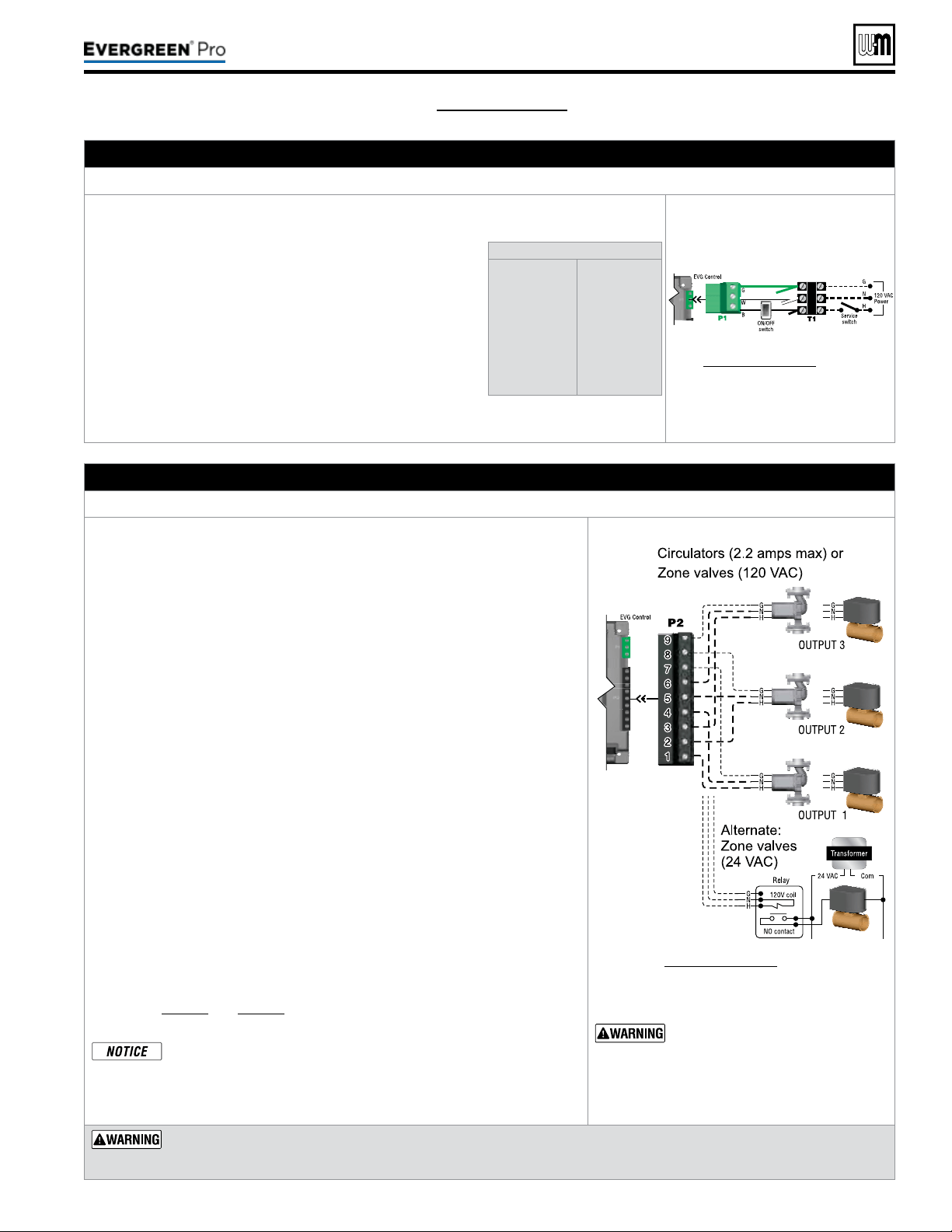
Part number 550-100-211/0122
– 53 –
220 /29 9/3 00 /39 9
(see wiring diagram, Figure 65, page 59)(continued)
A. 120 VAC Power Supply – REQUIRED
TerminalBlockT1(control tray, right front)
1. Provide and install a properly-sized, fused disconnect or
service switch as required by applicable codes. (15-amp for
most cases.)
a. Use table at right to determine total load. Suggested
fused disconnect or service switch sizing is 15-amp if
total load is 12amps or less, 20-amp if total load is more
than 12amps.
2. Connect properly sized 120 VAC power wiring to Ever-
green
®
boiler line voltage terminal strip T1 as shown at right.
3. If possible, provide a surge suppressor in the supply power
line. is will reduce the possibilities of control damage due
to line surges.
4. Must wire ground to this terminal to provide boiler ground-
ing.
Determinetotalload
Boiler & boiler pump
(combined load)
Output 1 . . . . . . .
(2.2 amps max)
Output 2 . . . . . . .
(2.2 amps max)
Output 3 . . . . . . .
(2.2 amps max)
TOTAL . . .
. . . .
8.4 amps
____ amps
____ amps
____ amps
____ amps
See Figure65,page59 for details
B. 120VACOutputs1,2&3 – As needed for systems
TerminalStripP2(EVG control module, right side)
1. Output1: P2 Terminals 1 (H), 4 (N), 7 (G).
2. Output2: P2 Terminals 2 (H), 5 (N), 8 (G).
3. Output3: P2 Terminals 3 (H), 6 (N), 9 (G).
4. Maximum load: 2.2 amps (use relay if circulator load is higher). See WARN-
ING below.
5. ese three outputs (Output 1, Output 2, and Output 3) can provide 120VAC
to the following listed below.
y A zone
circulator.
y A system circulator.
y A DHW circulator (used to circulate through an indirect tank).
y An auxil
iary item that must be energized during an input call, such as
an air damper.
6. When using inputs/outputs for heat/DHW demands, each input (Input1,
Input2, and Input3) controls its respective 120VAC output (Output1, Out-
put2, and Output3). Outputs are energized only when BOTH conditions
below are met:
a. e corresponding input indicates a call for heat/DHW (i.e. contact
closure).
b. e PRIORITY assigned to the Input/Output pair is ACTIVE (i.e. the zone
may be calling but the pump won’t activate unless the boiler is currently
running on that system/priority).
7. When using the inputs/outputs for the AUX PUMP/OUTPUT function, the
output is controlled by selectable conditions set up in the control.
a. Use the AUX PUMP/OUTPUT function for devices such as system
pumps, combustion air dampers, and other auxiliary equipment to activate
when the boiler is on/running.
b. See page78 and page79 for more information on the setup and selection
of operating conditions.
ForPriorityDHWApplication:
e DHW aquastat can be connected to any one of the three input/
output pairs. e selected input should be assigned to PRIORITY1
during the WIZARD setup or manually in the ASSIGN INPUTS
menu.
See Figure65,page59 for details.
Output circuits are 120 VAC. If
an output is to operate a low
voltage circuit or must be an
isolated contact, use an isola-
tionrelay.
CIRCULATORPOWER — Themaximumallow-
ablecurrentforeachcirculatoris2.2amps
at120VAC
.
For circulators with higher amp ratings, install a circulator relay
or starter. Connect only the 120-VAC coil to the Evergreen
circulator terminals.
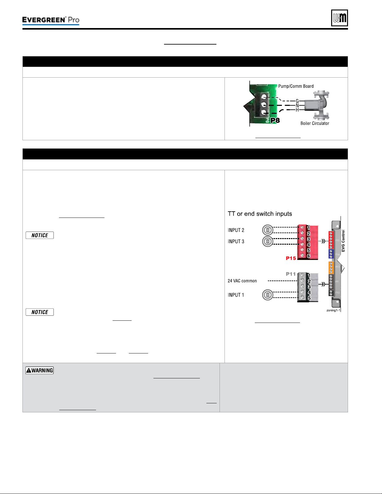
Part number 550-100-211/0122
– 54 –
(see wiring diagram, Figure 65, page 59)(continued)
C.120VACtoBoilerCirculator – REQUIRED
TerminalStripP8onPump/CommBoard(control tray, left side)
1. Provides 120VAC to the boiler circulator at Pump/Comm Board P8 Terminals.
2. Terminals are: 1 (H), 2 (N), 3 (G).
3. Maximum load: 2.2 amps (use relay if circulator load is higher). See WARN-
ING above.
4. e boiler circulator (shipped loose with boiler) is used in the boiler loop of
the primary / secondary piping. Primary / secondary piping is required to
be used with the Evergreen
®
boiler to ensure proper ow through the heat
exchanger.
See Figure65,page59 for details.
D. Inputs1,2and3(tstats,endswitches,etc.) – As needed for systems
TerminalStripP11(input1)&TerminalStripP15(inputs2&3)(EVG control module, left side)
1. Input 1 – Terminal Strip P11 – 4 & 5 (EVG control module)
2. Input 2 – Terminal Strip P15 – 1 & 2 (EVG control module)
3. Input 3 – Terminal Strip P15 – 3 & 4 (EVG control module)
4. ese three inputs on each boiler can indicate a call for heat to the control
by means of a dry contact closure (thermostat, aqua
stat, or switch). (See
right and Figure65,page59).
5. e control provides inputs for up to three zones or three systems (priorities).
e control default setting is for three space heating zones tied to
PRIORITY2, which is defaulted to FINNED TUBE BASEBOARD
system type.
6. For DHW applications, the aquastat can be connected to one of the three
input/output pairs. Take advantage of factory default settings by using PRI-
ORITY1 for the DHW system. e default control setting for PRIORITY1
is a direct-piped DHW system type.
7. e default control setting uses each input (INPUT1, INPUT2, and IN
PUT3) to control its respective 120VAC output (OUTPUT1, OUTPUT2,
and OUTPUT3).
Use of 0–10VDC input for modulation disables Input 1 from creat-
ing calls for heat. See page58 for instructions.
An input can be assigned to an AUX PUMP/OUTPUT function to
operate a system pump or interlock with a combustion air damper.
Inputs assigned for this function cannot be used for heat demand
operation. See page78 and page79 for more information on the
setup and selection of operating conditions.
See Figure65,page59 for details.
Thermostats — DONOT supply 24-volt power to the thermostat
circuits (Input1, Input2 and Input3 in
Figure65,page59
) or at-
tempt to supply 24volts for any other application.
For thermostats that require a continuous 24-volt power
source, connect the common wire (“C”) to
P11
Pin 2
(see Fig-
ure65,page59)
.
Do NOT exceed total amp draw per thermostat.
Zonevalves — If using 3-wire zone valves, use
relays to provide dry contacts to the Control ther-
mostat connections. e zone valve end switches of
3-wire valves carry 24VAC from the valve.
Thermostatanticipatorsetting — 0.1amps.
220 /29 9/3 00 /39 9
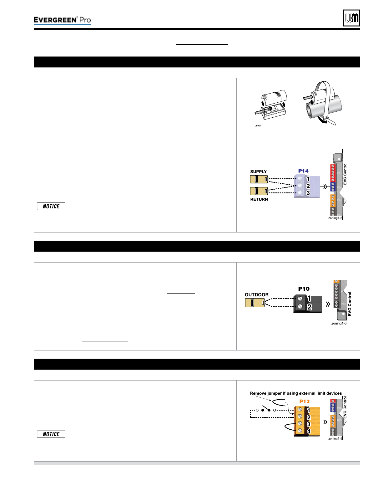
Part number 550-100-211/0122
– 55 –
220 /29 9/3 00 /39 9
(see wiring diagram, Figure 65, page 59)(continued)
E. Systemsupplyandreturntemperaturesensors – REQUIRED
TerminalBlockP14(EVG control module, left side)
1. Two strap-on temperature sensors are shipped with the boiler. Attach one
to the system supply piping and the other to the system return piping. For
piping larger than 5inch diameter or nonmetallic piping, using immersion
sensors will provide faster response.
2. Locate the supply sensor at least six pipe diameters, but no further than 3
feet, downstream from the boiler connection to the main to ensure adequate
mixing.
3. Supply sensor – wire between P14 #1 and #2 (common).
4. Return sensor – wire between P14 #3 and #2 (common).
5. ermostat wire can be used to connect these sensors.
6. e Control compares the system return temperature with the system supply
temperature. Should the return temperature ever exceed the supply tempera-
ture, the Control knows there is likely a sensor failure and will report this
problem on the display.
All heating systems shown in this manual require the System Sup-
ply and Return sensors to be installed for proper control function.
System will not properly provide heat if sensors are not installed
according to these instructions.
Strap to supply & return piping
See Figure65,page59 for details.
F. Outdoor temperature sensor – REQUIRED unless exempted
TerminalBlockP10(EVG control module, left side)
1. e control provides programmable options if using an outdoor tempera-
ture sensor. is sensor is supplied with the boiler.
2. Theoutdoorsensormustbeinstalledunlessspecicallyex-
emptedintheEnergyActstatementonpage129.
3. Mount the outdoor sensor on an exterior wall, shielded from direct sunlight
or ow of heat or cooling from other sources.
4. e wire outlet on the sensor must be oriented DOWN to prevent water
entry.
5. Connect the sensor leads to the terminal shown at right and in the wiring
diagrams (see Figure65,page59). ermostat wire can be used to connect
the sensor.
See Figure65,page59 for details.
G. External limits – OPTIONAL
TocauseM AN UALreset:TerminalBlockP13#1(EVG control module, left side)
EVGcontrolwillrequiremanualresetaftercircuitisinterrupted
.
1. Remove factory-installed jumper and connect isolated contacts of external
limits across P13 pins1 and2 to cause the control to enter manual reset
lockout if the limit circuit opens. e limit must close and the control must
be manually reset using the procedure given in this manual. See drawing
at right and wiring diagram (Figure65,page59).
e control will lockout when a limit in its manual reset circuit
opens (P13 pins1 &2). e control activates its alarm terminals
and shuts the boiler down. An operator (user or technician) must
manually reset the control to restart the boiler.
See Figure65,page59 for details.
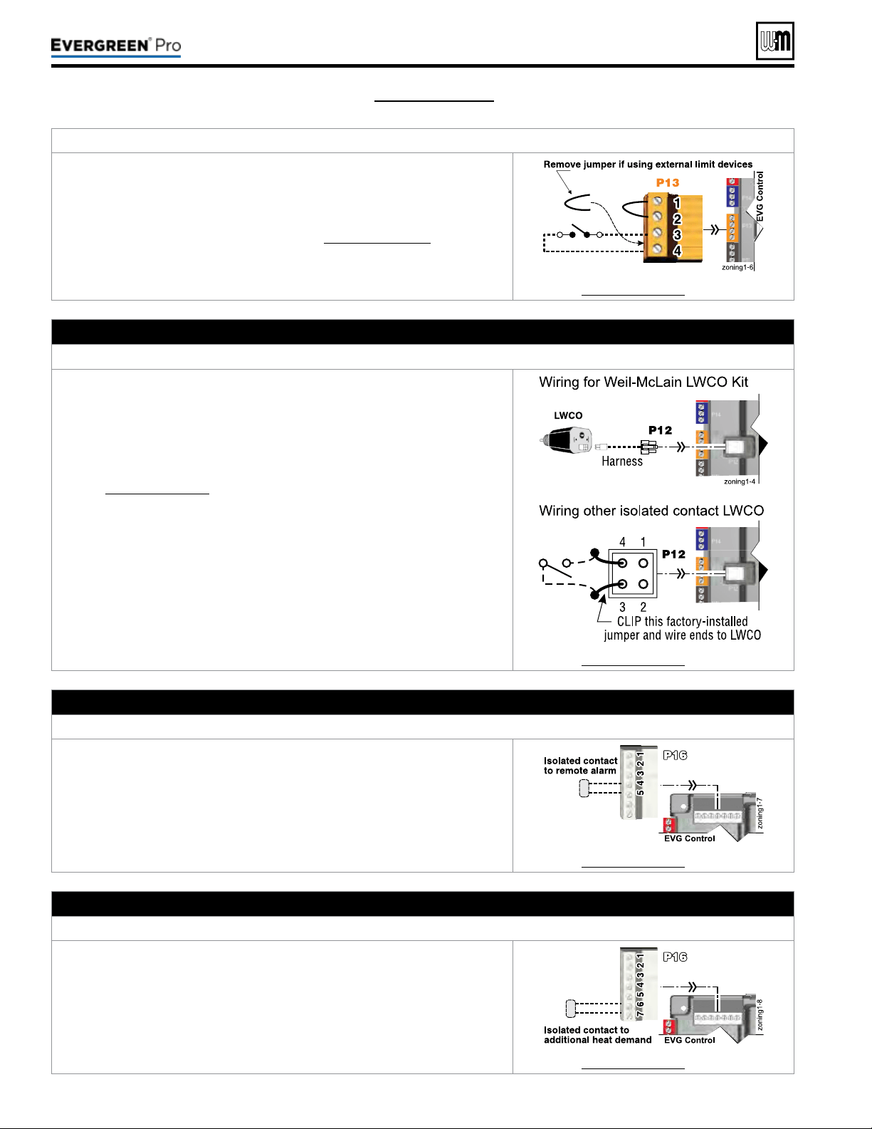
Part number 550-100-211/0122
– 56 –
TocauseAUTOMATICreset:TerminalBlockP13#3(EVG control module, left side)
EVGcontrolwillresetautomaticallyaftercircuitisinterrupted.
1. Remove factory-installed jumper and connect isolated contacts of external
limits across P13 pins3 and4 to cause the control to shut down the boiler on
limit opening, then automatically restart 150 seconds aer the limit closes.
2. See drawing at right and wiring diagram (Figure65,page59).
See Figure65,page59 for details.
H. Low water cuto – WHEN REQUIRED
TerminalBlockP12(EVG control module, left side)
1. Install a low water cut-o when required.
2. Wiring Weil-McLain LWCO Kit:
a. When possible, use the Weil-McLain Low water cut-o kit listed in the
back of this manual. It includes a probe-type low water cut-o and pro-
vides a simple harness connection for the wiring.
b. Connect as shown at top right and in the control wiring diagram
(Figure65,page59).
c. e Weil-McLain Low water cut-o kit is included with the boiler.
3. Wiring another LWCO — must have isolated contact:
a. Other low water cut-os can be used with the EVG only if the device uses
an isolated contact for the LWCO function.
b. Connect as shown at bottom right.
See Figure65,page59 for details.
I. Alarm contacts – OPTIONAL
TerminalBlockP16#4(EVG control module, top left)
1. e control’s alarm dry contact (P16, terminals 4 and 5) closes when the
boiler enters manual lockout only.
2. Connect these terminals for remote alarm notication.
3. Contact electrical ratings: 24VAC or less; 0.5 amp or less.
See Figure65,page59 for details.
J. Additional heat demand contacts – OPTIONAL
TerminalBlockP16#6(EVG control module, top left)
1. e control module can be set to activate another heat source using its ad-
ditional heat demand dry contacts through terminal block P16 pins6 &7.
2. Connect these terminals to call for heat from the other heat source.
3. Contact electrical ratings: 24VAC or less; 0.5 amp or less.
4. Set the control to activate the heat demand contacts as needed.
5. See EVG Advanced Manual to congure.
See Figure65,page59 for details.
(see wiring diagram, Figure 65, page 59)(continued)
220 /29 9/3 00 /39 9
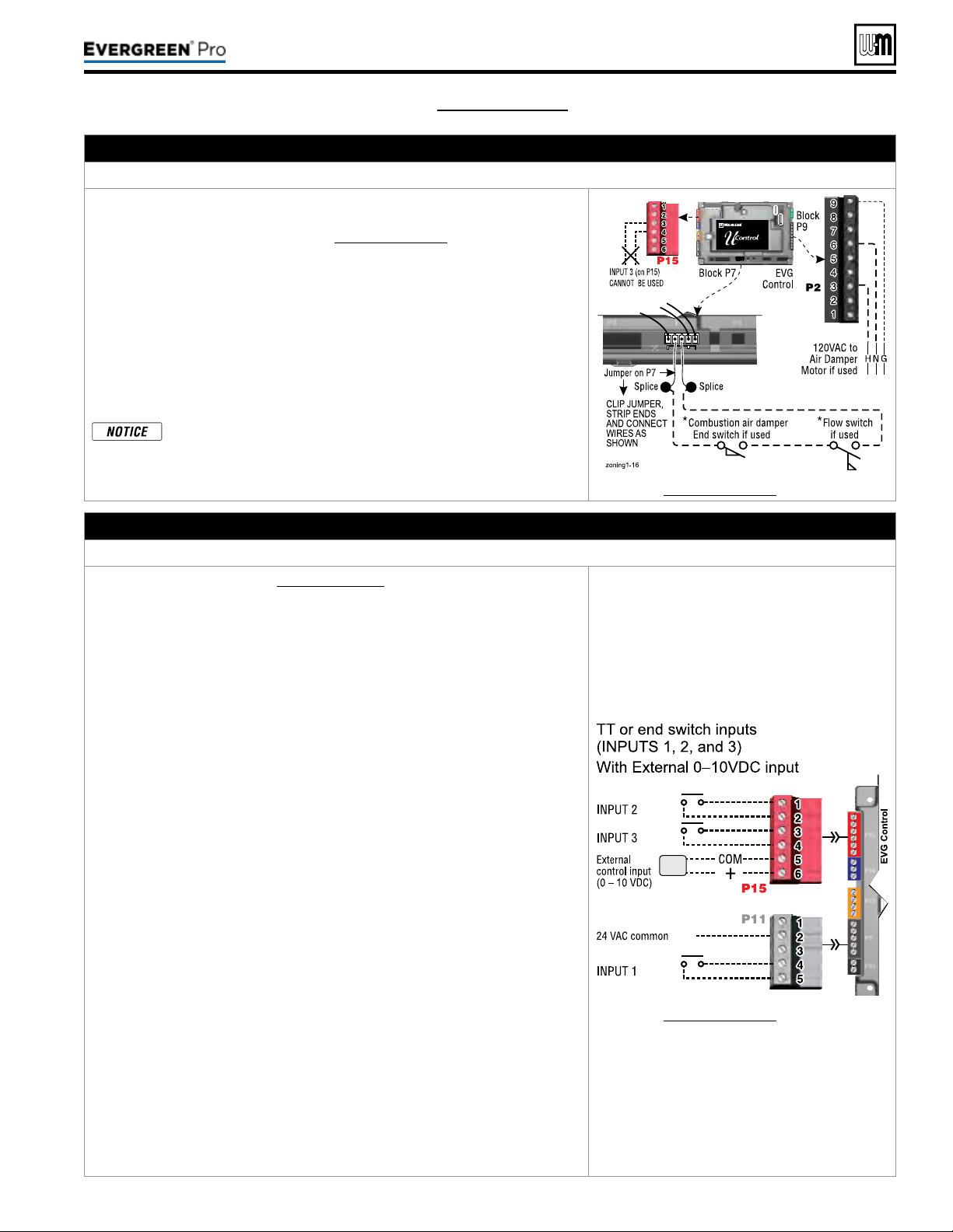
Part number 550-100-211/0122
– 57 –
220 /29 9/3 00 /39 9
K. Proof of closure (ow switch and/or CAD) – see ADVANCED Manual
– OPTIONAL
JumperonTerminalStripP7(EVG control, bottom left of center)
1. A ow switch or combustion air damper (CAD) interlock can be congured
by clipping the jumper on terminal strip P7 and wiring components as shown
at right and in the wiring diagram (Figure65,page59).
2. No control settings are required when using a ow switch.
3. Recommended conguration of the EVG control for a CAD interlock:
a. Assign INPUT3 as a AUXPUMP/OUTPUT function.
b. For the AUX PUMP/OUTPUT operating mode, select ANY BURNER
DEMAND
. is ensures the damper will be activated any time the boiler
is called on to re.
c. OUTPUT3 will provide 120VAC to the damper motor. Use an isolation
relay if damper motor requires another voltage or more than 2.2 amp if
using 120 VAC.
*
e devices used must provide electrically isolated contacts,
because the P7 jumper circuit carries 5VDC.
See Figure65,page59 for details.
L. 0–10 VDC Remote TARGET input – OPTIONAL
TerminalBlockP15#5(EVG control module, left side)
1. See illustration at right and Figure65,page59 (wiring diagram) for details.
2. Remote target using 0–10VDC input requires a 0–10VDC input signal at P15-4/5
as shown at right.
a. e input positive connection must be at P15 terminal6 and the common
connection at terminal5.
3. is illustration also shows how to connect TT or end switch contacts at INPUT1,
INPUT2 and INPUT3.
a. If a Heat/DHW demand is required, connect the demand’s dry contact to
an unused input on the control and its pump/valve to the respective output.
en assign and setup a priority to the input using the Wizard or manually
through the contractor menu.
b. A dry contact heat demand must be applied to one of the inputs in order to
initiate a call for heat.
4. e 0–10VDC signal is used to adjust the supply target temperature, using the
TARGET ADJUST setting. Set TARGET ADJUST during the WIZARD or
manually in the PRIORITY SETTINGS menu for the desired system/ priority.
a. Many options are available for conguring the control. e following is a
suggested setup that uses factory default settings as much as possible.
b. Use PRIORITY1 for the DHW heating system when used. is priority’s
default values are set for DHW, direct-piped to the boiler. Verify that settings
are suitable for the application, change if needed.
c. Use PRIORITY2 for the heating systems.
y For single boilers, the factory default settings for PRIORITY 2
make this priority a good choice for space heating applications.
Set PRIORITY2 values to the following:
y Set TARGET ADJUST value to 0–10V.
y Set VOLTS FOR MAX at the voltage that will call for the highest target
temperature. Set SUPPLY MAX at this temperature.
y Set VOLTS FOR MIN at the voltage that will call for the lowest target
temperature. Set SUPPLY MIN at this temperature.
y For voltages between VOLTS FOR MAX and VOLTS FOR MIN, the
target temperature will range proportionately between SUPPLY MAX
and SUPPLY MIN. See the EVG Advanced Manual for a full discussion.
y NOTE: e 0–10VDC signal replaces the ODT sensor as the target
temperature modier (TARGET ADJUST setting). e EVG control
does not control target.
See Figure65,page59 for details.
(see wiring diagram, Figure 65, page 59)(continued)
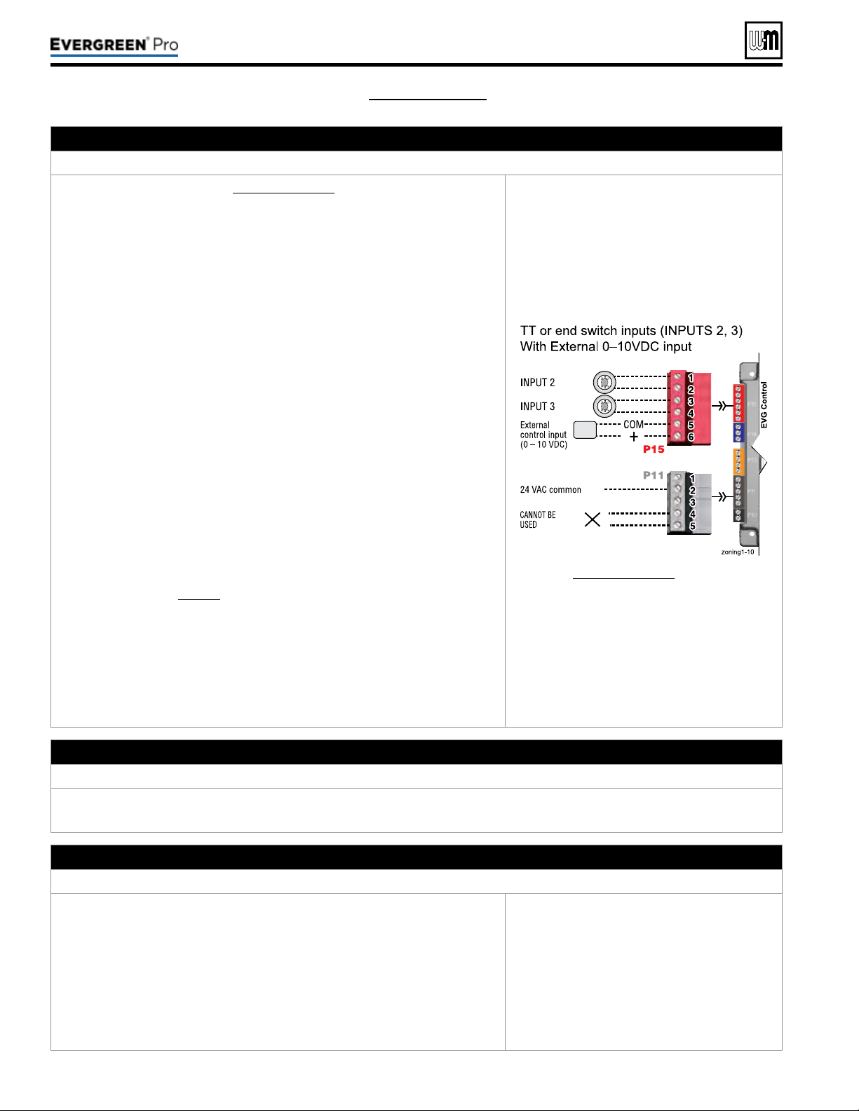
Part number 550-100-211/0122
– 58 –
(see wiring diagram, Figure 65, page 59)(continued)
M. 0–10 VDC Remote MODULATION input – OPTIONAL
TerminalBlockP15#5(EVG control module, left side)
1. See illustration at right and Figure65,page59 for details.
2. is illustration also shows how to connect TT or end switch contacts at
INPUT2 and INPUT3 for other uses.
3. Note that using 0–10VDC input replaces INPUT1 for generating a heat
demand. Do not wire any input to INPUT1 as shown at right.
4. Remote modulation requires a 0–10VDC input signal at P15-4/5 as shown
at right.
a. e 0–10VDC input positive connection must be at terminal6 and com-
mon connection at terminal5.
5. Control setup:
a. Many options are available for conguring the control. e following is
a suggested setup that uses factory default settings as much as possible.
b. Default is BASIC in the Contractor menu.
c. If DHW is required, use PRIORITY1 to minimize setup steps.
y Connect the DHW aquastat to INPUT2 or INPUT3 and assign the
input used to PRIORITY1.
y Verify that control settings are suitable for the application, change
if necessary.
d. Use PRIORITY2 for the system to be remote modulated.
y e factory default settings for this priority are best suited for space
heating.
y Assign INPUT1 to the priority chosen. Accept all defaults for IN-
PUT1 — no changes should be necessary during the WIZARD.
y Aer the WIZARD has been completed, go to the ASSIGN INPUTS
menu for INPUT1. Change SOURCE to 0–10V (default setting is
TT1). See page78 for ASSIGN INPUTS menu information.
6. Operation:
a. e boiler comes on at 0.9VDC and turns o at 0.8VDC. 1VDC = 10%
input. 10VDC = 100% input. ese voltage settings are not adjustable.
b. OUTPUT1 (120VAC) is activated and deactivated as the heat demand is
turned on and o. is output is a good choice to operate the system pump.
7. NOTE: e EVG control can be congured to use either 0–10VDC for target
operation (see previous section) or modulation,
butnotboth.
See Figure65,page59 for details.
N. 120VAC Power Receptacle
Locatedonboilerrightsidepanel
1. Electrical rating is 2.0amps max at 120VAC.
2. is receptacle can be used to plug in a condensate pump.
O. Multiple Boiler and BMS Connections – see ADVANCED Manual
TerminalStripsP4andP5onPump/CommBoard(control tray, left side)
1. e boiler control is capable of multiple boiler communication and control
of up to eight Evergreen
®
boilers in one installation.
2. e boiler control is also capable of BMS communication.
3. e boiler control is also capable ZoneStacking
TM
:
Uses All boiler inputs, not just the rst and last boilers, up to 24 customiz-
able inputs across boiler network (3 per unit, maximum of 8 boilers on the
network).
4. See Evergreen
®
Advanced Manual for multiple boiler installation and setup
information.
See EVG Advanced Manual for details.
220 /29 9/3 00 /39 9
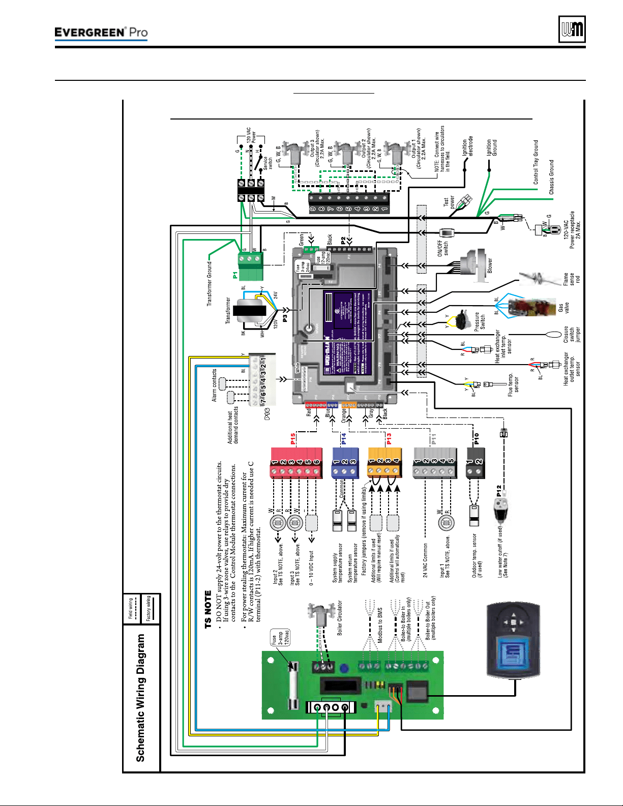
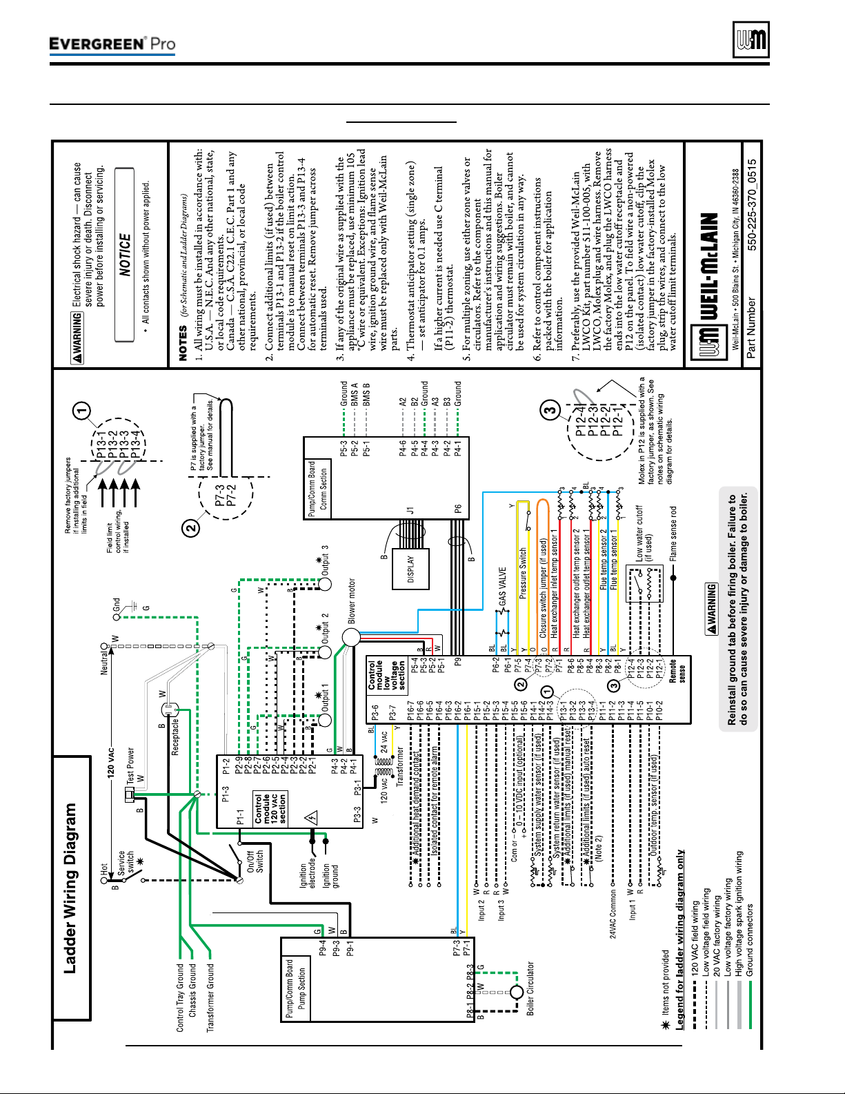
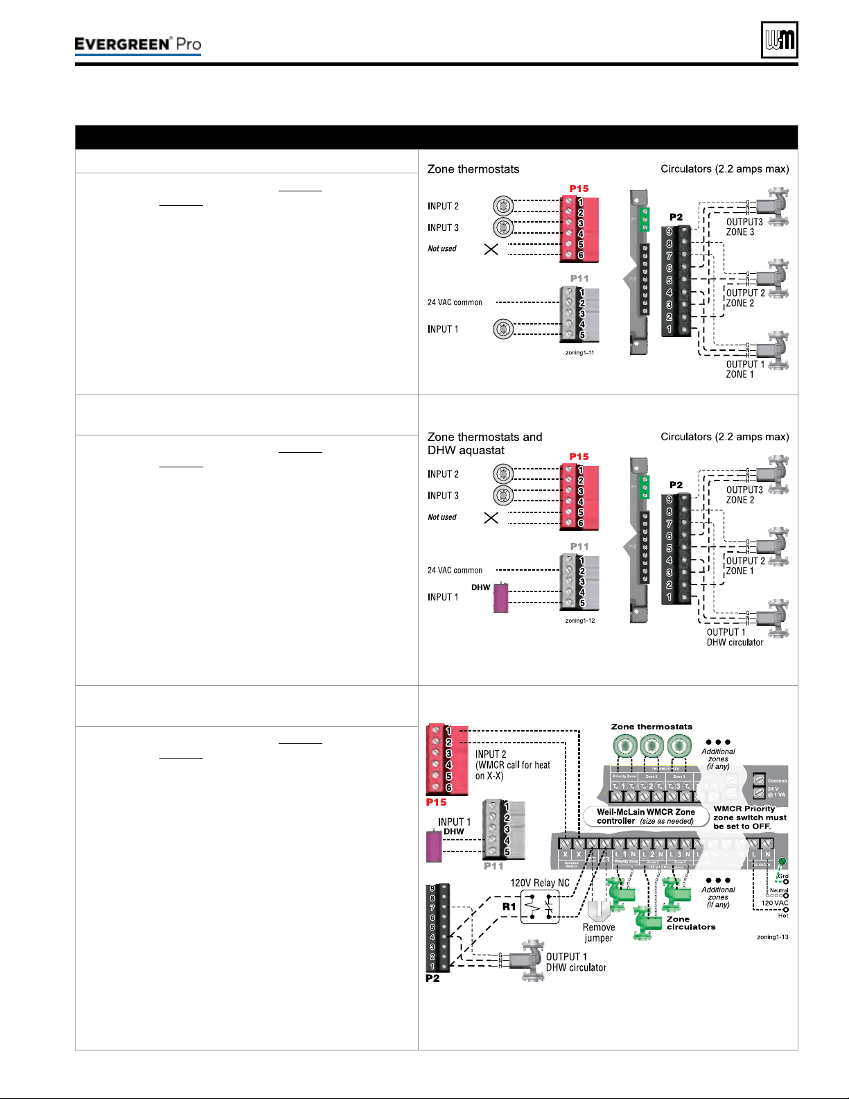
A. Zoning with CIRCULATORS, suggested applications
Threespaceheatingzones(noDHW)
1. Review wiring information on page53 (120VAC out-
puts) and page54 (24VAC inputs).
2. e conguration at right uses the three input/output
pairs to receive thermostat inputs on P11-4/5, P15-1/2,
and P15-3/4; and circulator outputs on P2 as shown.
3. e factory default settings assign all inputs 1, 2 and3
to PRIORITY 2.
4. Choose the space heating system type that matches the
heating system during the WIZARD setup or manually
in the PRIORITY2 menu.
5. Use the factory default settings for the system type
chosen, or change if needed.
6. Factory defaults should work for other settings not
listed above.
TwospaceheatingzonesplusDHWpiped
directlytoboiler
1. Review wiring information on page53 (120VAC out-
puts) and page54 (24VAC inputs).
2. e conguration at right uses INPUT2 and3 for space
heating thermostats. INPUT1 uses the input from a
DHW aquastat.
3. e factory default settings assign inputs 1, 2 and3 to
PRIORITY 2. Keep inputs2 and3 assigned to PRIOR
-
ITY2. To set up PRIORITY2, choose the space heating
sys
tem type that matches the heating system during the
WIZARD setup or manually in the PRIORITY2 menu.
4. Assign INPUT1 to PRIORITY 1, which is factory
default congured for DHW applications.
5. Use the factory default settings for DHW and for the
heating system type chosen, or change if needed.
6. Factory defaults should work for other settings not
listed above.
WMCR circulator zone controller plus DHW
controlledbyboiler,DHWpipeddirectlytoboiler
P15, P11 and P2 are terminal strips on the EVG control.
1. Review wiring information on page53 (120VAC out-
puts) and page54 (24VAC inputs).
2. To shut down Space Heating during DHW operation:
Provide and connect relay R1 (120VAC coil with NC
contact) to interrupt the Zone controller’s ZC-ZR
(120VAC operating circuit).
3. e conguration at right uses INPUT2 for space
heating with the call for heat coming from the zone
controller (X-X). INPUT1 uses the input from a DHW
aquastat.
4. e factory default settings assign inputs 1, 2 and3 to
PRIORITY 2. Keep input2 assigned to PRIORITY2.
To set up PRIORITY2, choose the space heating sys
-
tem type that matches the heating system during the
WIZ
ARD setup or manually in the PRIORITY2 menu.
5. Assign INPUT1 to PRIORITY 1, which is factory
default congured for DHW applications. Wire the
DHW circulator to OUTPUT1.
6. Use the factory default settings for DHW and for the
heating system type chosen, or change if needed. Fac
-
tory defaults should work for other settings not listed
ab
ove.
Part number 550-100-211/0122
– 61 –
220 /29 9/3 00 /39 9
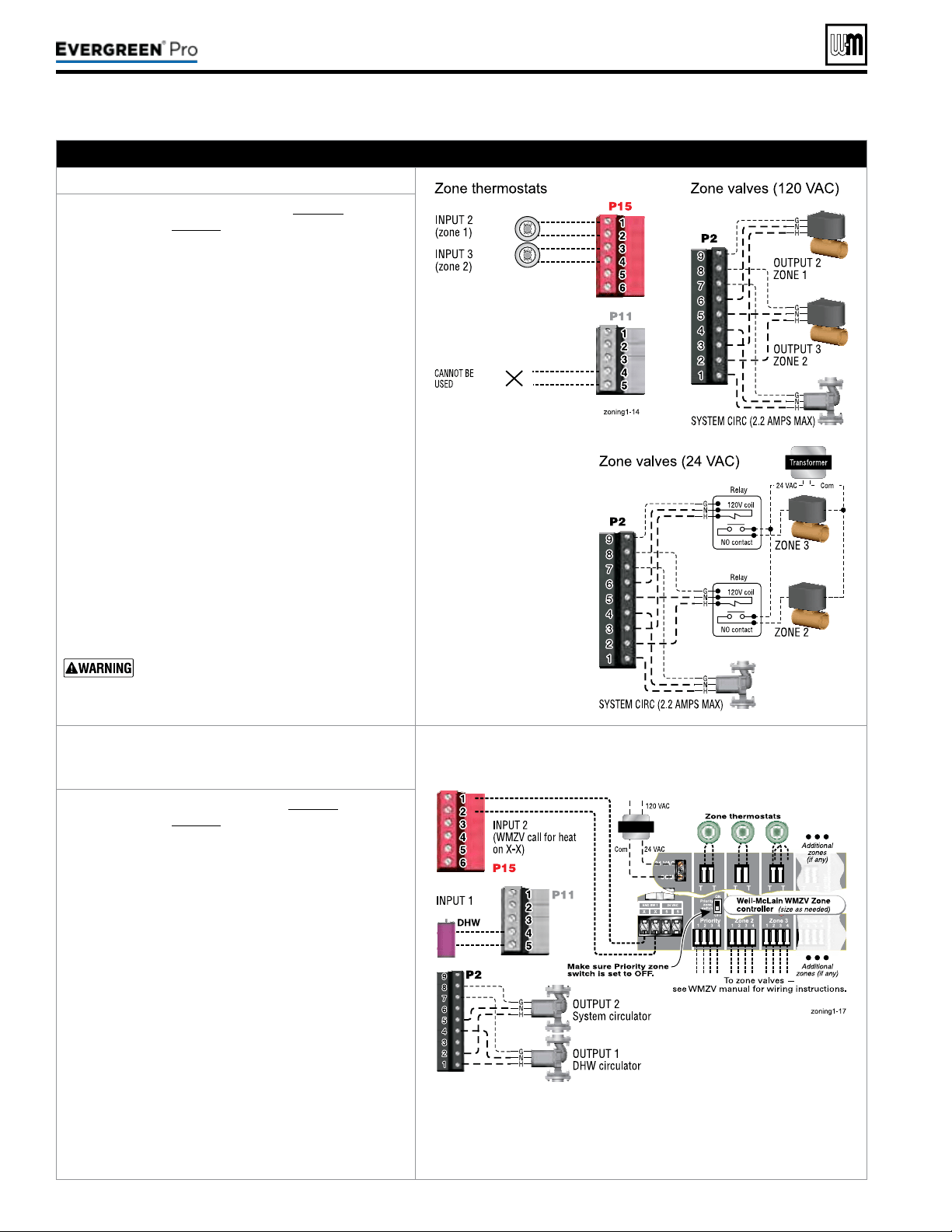
(continued)
B. Zoning with ZONE VALVES, suggested applications
Twospaceheatingzones(noDHW)
1. Review wiring information on page53 (120VAC
outputs) and page54 (24VAC inputs).
2. e conguration at right uses INPUT2 and3 for
space heating thermostats. INPUT1 is reserved
here for conguring the operation of the system
circulator.
3. e factory default settings assign inputs 1, 2 and3
to PRIORITY 2. Keep inputs2 and3 assigned to
PRIORITY2. To set up PRIORITY2, choose the
space heating system type that matches the heating
system during the WIZARD setup or manually in
the PRIORITY2 menu.
4. Use the factory default settings for the heating sys
-
tem type chosen, or change if needed.
5.
Assign INPUT1 to AUX PUMP/OUTPUT. en
select ANY INPUT BY ITS PRIORITY when
prompted for when to activate the output. is will
cause the system pump to run when either of the
zones calls for heat. Conrm that Priority2 RUN
AUX PUMP/OUT is set to YES.
6. INPUT1 (P11-4/5) cannot be used for a wired con
-
nection (as shown at right) because it is being used
in t
he control setup to run the system circulator.
7. Factory defaults should work for other settings not
listed above.
e system must be equipped with a by-pass
pressure regulating valve. Flow can occur
with zone valves closed.
WMZVzonevalvezonecontrollerplus
DHWcontrolledbyboiler,DHWpiped
directlytoboiler
P15, P11 and P2 are terminal strips on the EVG control.
1. Review wiring information on page53 (120VAC
outputs) and page54 (24VAC inputs).
2. e conguration at right uses INPUT2 for space
heating with the call for heat coming from the zone
controller (X-X). INPUT1 uses the input from a
DHW aquastat.
3. The factory default settings assign inputs 1, 2
and3 to PRIORITY 2. Keep input2 assigned to
PRIORITY2. To set up PRIORITY2, choose the
space heating system type that matches the heating
system during the WIZARD setup or manually in
the PRIORITY2 menu.
4. e system circulator, wired to OUTPUT2, will
turn on whenever there is a call for heat from the
zone controller.
5. Assign INPUT1 to PRIORITY1, which is factory
default congured for DHW applications. Wire the
DHW circulator to OUTPUT1.
6. Use the factory default settings for DHW and
for the heating system type chosen, or change if
needed. Factory defaults should work for other
settings not listed above.
Part number 550-100-211/0122
– 62 –
220 /29 9/3 00 /39 9
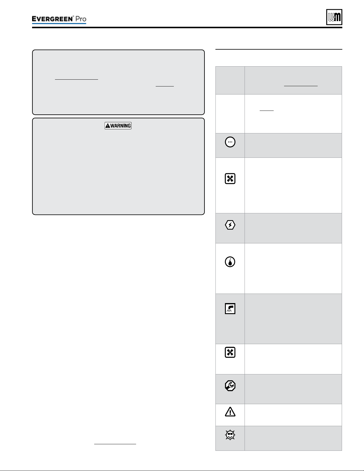
Part number 550-100-211/0122
– 63 –
220 /29 9/3 00 /39 9
1. Set control parameters using the WIZARD option provided on
initial start-up or manually enter parameters using control menus
(see Figure74,page75 and following pages for information.)
2. See
Expresssetup
instructions beginning on page68 for basic
systems and minimum settings required (using factory defaults).
3. is manual provides set-up information for a single boiler using
BASIC control setting options. See the EVG Advanced Manual for
single-boiler advanced settings and for all multiple boiler applications.
BoilerModel,AltitudeandFuelTypearecriticalsettings.
Failure to set correctly could result in severe personal injury, death or
substantial property damage.
Temperaturesettings — You must ensure that the Evergreen control
is set for the proper water temperatures for the system. Excessive water
temperature can cause signicant property damage in some applications.
Multi-temperaturesystems — If the heating system includes circuits
that require lower temperature water (radiant slab circuits, for example)
as well as higher temperature circuits (DHW, nned tube baseboard,
etc.), it is recommended to protect low-temperature circuits with limit
controls that are wired to an Evergreen
®
control external limit circuit.
Failure to provide regulation can result in substantial property damage.
Single or multiple boiler control (with lead boiler rotation).
Graphic and robust text display for ease of operation monitoring and
troubleshooting.
ree programmable priority assignments for up to three heat inputs.
Preset operating parameters for typical heating systems, including target
temperatures, reset curves and circulator assignments.
Integral outdoor reset option, with reset curves matched to the system
type selected.
ModBus communications for external communication and monitoring.
0-10VDC input modulation or remote target input.
Four pump outputs, including 1 boiler pump output.
Additional heat demand operation to call a second heat source to help
supply the energy required for heating.
Advanced PI response to anticipate system needs.
Flue temperature modier to target temperature.
Modulation based on ue sensor and boiler/system supply/return sensors.
Integral low water protection by monitoring heat exchanger temp.
Dual temperature sensors on boiler outlet and ue, providing redundant
protection.
Boiler is shipped with an outdoor sensor and strap on system supply
and return sensors.
Blower speed modulation to control boiler ring rate.
Alarm relay on error/fault for use with an audible safety.
ZoneStacking
TM
– Uses All boiler inputs, not just the rst and last boilers,
up to 24 customizable inputs across boiler network (3 per unit, maximum
of 8 boilers on the network).
SmartSequencing
TM
–
Uses a low ring rate setting, called BASERATE
LOW, to keep boilers at a low ring rate, bringing on additional boilers at
reduced rate until all boilers are on if necessary. Boilers are then allowed
to modulate together as high as necessary to meet demand.
1. Figure67 is a summary of the operating sequence for the Evergreen
®
control.
y e statuses shown appear in the display as the Evergreen
®
control
cycles the boiler. See Figure71,page67 for screen shots.
y e display will ash red if a problem has been detected.
Figure67 Control sequence of operation
Display
status
text
Controlaction
(also see Figure71,page67)
POWER
UP
y Check the boiler model listed on the power-up
screen. If it is not correct, turn o the boiler.
See page76 for instructions to change setting.
y When power is turned on, the screen lists sen
-
sors that are detected. If any sensor is not listed,
m
ake sure it is connected correctly. Turn o
power and restart.
Standby
y Standby - no calls for heat.
y Toggles through no dots, 1 dot, 2 dots, then 3
dots while in standby (wrench symbol will show
instead if maintenance is needed).
Blower
ON
y Call for heat detected.
y Display on with BLUE light (space heating) or
PURPLE light (DHW).
y Start min/max timers if more than one system is
calling - highest priority starts rst.
y Start circulators for this priority setup based
upon settings.
y Calculate target temp — If sensor temp is below
target temp, begin ring sequence.
y Blower to ignition speed for prepurge.
Ignition
y Aer prepurge times out, begin ignition cycle.
y Activate gas valve and ignition spark.
y Continue ignition spark for ignition period.
y Turn o spark and use electrode to check for
ame signal.
Space
Heating
y Flame detected.
y Release boiler to modulation.
y NOTE: If ame is not detected, the gas valve
is turned o, blower turns on (postpurge), and
control starts cycle again. Aer 5 failures, the
control waits 60 minutes, then tries again.
y If priority timer times out, switch to next priority
and start priority timer.
y If demand satised, go to postpurge.
DHW
Heating
y Flame detected.
y Release boiler to modulation.
y NOTE: If ame is not detected, the gas valve
is turned o, blower turns on (postpurge), and
control starts cycle again. Aer 5 failures, the
control waits 60 minutes, then tries again.
y If priority timer times out, switch to next priority
and start priority timer.
y If demand satised, go to postpurge.
Blower
OFF
y Demand satised (temperature reaches target
temperature or limit setting).
y Gas valve o.
y Blower to ignition speed for postpurge.
y Return to standby aer purge.
Maintenance
y Display turns BLUE, toggling between graphic
screen and maintenance screen (occurs if main-
tenance schedule timer times out).
y Will show during standby only.
y Boiler operates as normal.
Error/fault
y Display turns RED due to error or limit event.
y Flashing display means lockout condition.
WWSD
y Warm weather shut down - the boiler will not
be allowed to re on space heating if the outside
temperature is greater than the WWSD setting.
y DHW operation is not aected by WWSD.
(continued)
y For heating installations with multiple systems, the EVG control
uses PRIORITIES to determine the order of operation of the sys-
tems. e control’s MAX and MIN time settings determine the
maximum and minimum times a system will be operated before
being turned o to allow another system to operate. A typical
example is DHW priority — heat demand from the DHW system
is given preference over space heating, if set to use Priority 1.
y Each PRIORITY has its own set of operating parameters. e
control prompts the user to select the system type (nned tube
baseboard, DHW, etc.) and is factory programmed with param-
eters suited to each of these system types. e user can also choose
CUSTOM to create a system type.
y e EVG control provides up to three priorities for single boiler
applications and up to four priorities for network boiler appli-
cations. e order of operation is: PRIORITY 1, PRIORITY 2,
PRIORITY 3.
y e 120VAC power output to the boiler circulator is provided by
a relay located on the boiler’s Pump/Communications Board. For
each of the priorities, the control can be setup to run the boiler
pump or to leave it o. It is recommended to set Blr Circ to OFF
for DHW that is directly piped with its own DHW Circ.
y Each boiler has three input/output pairs (INPUT/OUTPUT1,
2 and3. Control setup prompts the user to assign each of these
I/O pairs to a PRIORITY. e EVG control then knows which
system (priority) to operate when the input receives a call for
heat. On a call for heat to an input, the EVG control closes the
corresponding output (120VAC) and begins controlling the boil-
ers according to the setup for the assigned priority.
y e MAX ON TIME setting controls the maximum time a priority
will be allowed to run before switching to a lower priority’s call
for heat. e MIN ON TIME setting controls the minimum time
a priority will be operated before switching to a higher priority’s
call for heat, or the next lower priority.
y When multiple inputs are set up on the same priority, they will
run at the same time if the priority and inputs are active.
y e control responds to signals from:
y Room thermostats.
y DHW aquastats (if used).
y Temperature sensors (boiler return, boiler supply, flue
temperature) and, when used, system supply and system
return, outdoor temperature). Foroptimalperformance,it
isrecommendedtoinstallthesystemsupplyandreturn
sensors.
y e control automatically adjusts blower speed (and gas ow
rate) to match boiler output to space heating and/or DHW heat-
ing demand.
y e control provides three inputs and three outputs (for circula-
tors or auxiliary devices) plus a fourth boiler circulator output.
y Outdoor reset must be used in all applications that are not exempt
as described on page129.
y e outdoor temperature is used for supply temperature reset
operation and for the warm weather shut down (WWSD)
option.
y System presets:
y e Evergreen control provides presets by system type (see
Figure73,page74 for complete list).
Part number 550-100-211/0122
– 64 –
• DETERMINE input/output needs –
• What are the inputs? – Thermostats, remote contacts,
end switches, etc.
• What does each control’s output need to do? – operate a
pump, activate an air louver, etc.
• Connect wiring to the control inputs and outputs to
accomplish the purposes set in Step 1.
• Install the boiler following all instructions in the Evergreen
Boiler Manual before proceeding further.
• See the Advanced Manual for multiple boiler installations.
• Follow instructions in the Boiler Manual to start up and
power the boiler.
• Use the WIZARD (below) or enter control parameters
manually (skip Wizard).
y e Wizard is available on initial setup of the boiler. It leads
through a step-by-step setup procedure designed for the
application chosen.
y Context-sensitive help is available to explain the purpose
of key setup items.
y Advanced settings for single boiler applications can be ac-
cessed manually from the Contractor menu.
Boiler
Settings
• Altitude –
– must be set correctly for proper
operation.
• WWSD – set outdoor temperature above which space
heating will be deactivated.
• Fuel (natural gas or propane) –
– must be set
correctly for proper operation – control will pause until
this value to selected.
Inputs/
Outputs
• Select the usage of inputs 1, 2 and 3.
• Determine usage of outputs 1, 2 and 3 (outputs
correspond to inputs).
Set
Priorities
• Assign priorities 1, 2 and 3 to the inputs.
System
Settings
• Set system settings or leave at their defaults.
System
Types
• Specify what system type is connected to each of the
three outputs; each system type causes the control to
preset. operating temperatures.
Output
Activation
• (When applicable) Select when to activate AUX PUMP/
OUTPUT – by input, always on, external switch, etc.
Priority
Switching
• Set maximum and minimum timings for priorities.
Date/Time
• Set date and time – important for control diagnostic
logging.
Information
• Set installer name and contact information.
• Enter CP#, install date, maintenance date, etc.
• Set automatic maintenance notication timing.
220 /29 9/3 00 /39 9
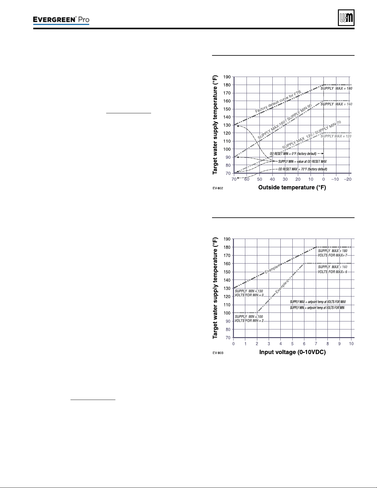
(continued)
Figure68 Outdoor reset operation
Figure69 Remote target operation
1. Set desired temperatures for space heating zones.
2. For an explanation of the target temperatures and associated
outdoor temperatures, see Figure68.
3. e temperature settings discussed below are accessed in the
priority menu for the applicable system. For detailed explanations
of the priority menus, see Figure76,page77.
SUPPLYMAX
1. Set Supply max to the required supply water temperature for the
system at design maximum heat loss (typically 180°F for nned
tube baseboard on new installations).
SUPPLYMIN
1. Supply min should equal the desired minimum supply water
temperature for the system.
2. is could be set as low as 70°F, which would supply “zero heat”
when outdoor temperature is 70°F, because supply water tem-
perature would equal room temperature.
3. See examples in Figure68.
ODRESETMAX
1. OD RESET MAX means the outdoor temperature at which the
target temperature reaches its minimum (Supply min).
2. In the examples of Figure68, this occurs at 70 °F (the factory
default).
ODRESETMIN
1. OD RESET MIN means the outdoor temperature at which the
target temperature reaches its maximum value (Supply max).
2. In the examples of Figure68, this occurs at 0°F outside (the fac-
tory default setting).
3. OD RESET MIN should equal the ODT (outdoor design tem-
perature) for the installation’s location.
1. is function allows a remote analog input to regulate the supply
temperature for control operation/modulation. is can be done
for any priority, including network and local priorities for multiple
boiler networks.
2. e settings discussed below are accessed in the priority menu
for the applicable system. For detailed explanations of the priority
menus, see Figure76,page77.
3. See Figure69 for an explanation of target temperature vs voltage
when using remote target operation.
4. In the priority menu for the applicable system, select 0-10v for
the TARGET ADJUST setting.
5. In the same priority menu, select the VOLTS FOR MIN and
VOLTS FOR MAX values. VOLTS FOR MIN sets the voltage
value for the desired minimum supply temperature. VOLTS FOR
MAX sets the voltage value for the desired maximum supply
temperature.
1. To use 0-10VDC for remote modulation, go to Con-
tractor Menu -> Assign Inputs. en change Input 1’s
source to 0-10V. e priority that is assigned to Input
1 cannot be used by any other Input.
2. e boiler comes on at 0.9VDC and turns o at 0.8VDC.
1VDC = 10% input. 10VDC = 100% input. ese volt-
age settings are not adjustable.
Part number 550-100-211/0122
– 65 –
220 /29 9/3 00 /39 9
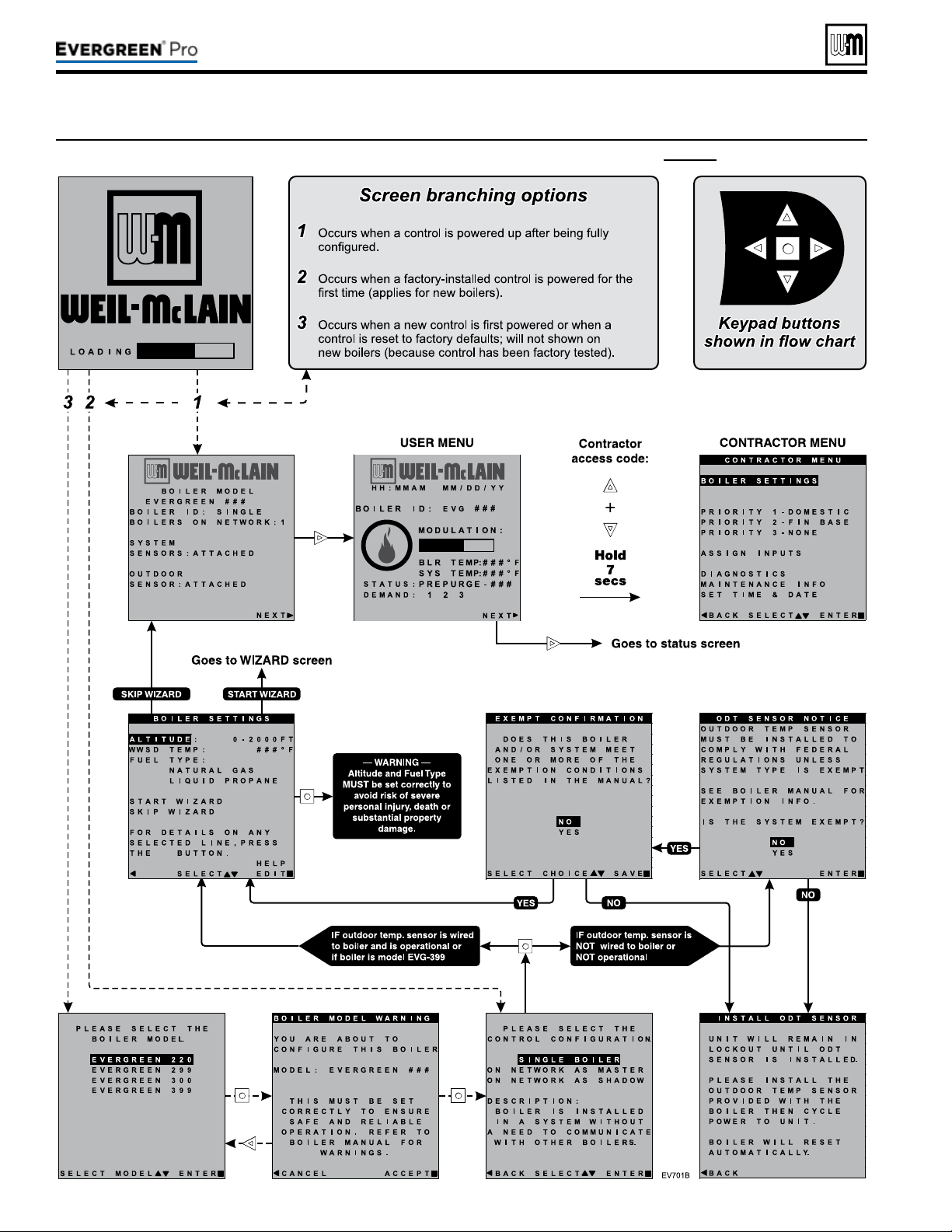
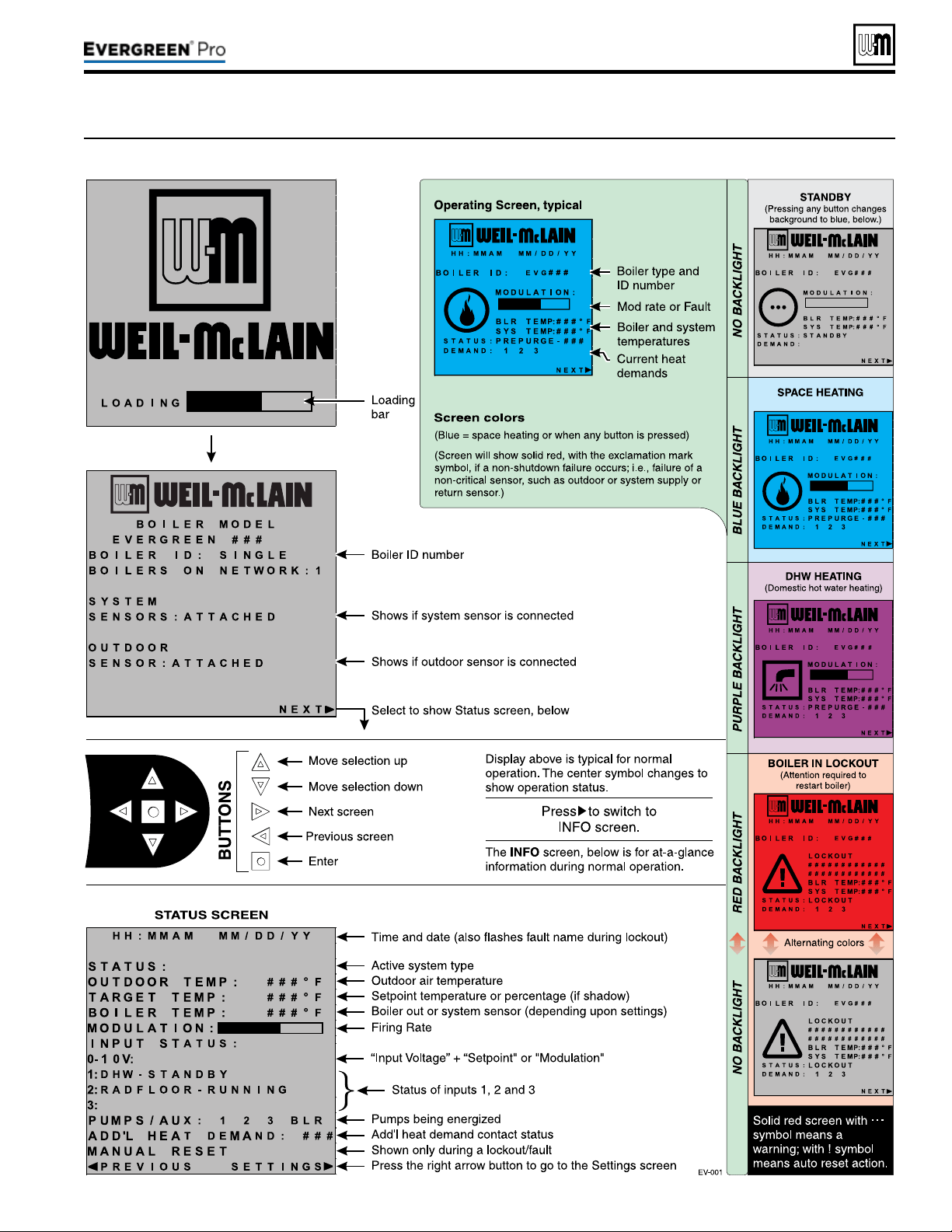
Part number 550-100-211/0122
– 67 –
220 /29 9/3 00 /39 9
(continued)
Figure71 Evergreen control display screens and typical navigation
Part number 550-100-211/0122
– 68 –
A
Multi-zoneSPACE H EATING(Circulatorswithcirculatorrelays)|DHW
(Direct-piped)
EVG
(in order of WiZArd sequences)
RED — vAlue must be set or verified
d — defAult AcceptAble; chAnge only
if desired
BOILER SET TI NGS
BOILER MODEL
Verifymodelnumberiscorrect
WWSDTEMP
Default(70°F)orasrequired
HIGHALTITUDE
Settoaltitudeifover2,000feet
(Assign to PRIORITY 1)
WHATISTHEUSEOFINPUT/OUTPUT1?
HEAT/DHWDEMAND
WHATPRIORITYISINPUT#1?
select
PRIORITY1
WHATSYSTEMTYPEISINPUT/OUTPUT1?
DHW(D)
TARGETMODSENSOR
BOILEROUT(D)
TARGETADJUST
NONE(D)
SUPPLYMAX
D (or change if desired)
RUNBOILERPUMP?
NO(D)
RUNAUXPUMP/OUTPUT?
D (not applicable)
IN PU T/OUT PU T 2 (Assign to PRIORITY 2)
WHATISTHEUSEOFINPUT/OUTPUT2?
HEAT/DHWDEMAND
WHATPRIORITYISINPUT#2?
PRIORITY2
WHATSYSTEMTYPEISINPUT/OUTPUT2?
Selectcorrectsystemtype
TARGETMODSENSOR
SYSTEMSUPPLY(D)
TARGETADJUST
ODT(D)
(outdoor sensor must be installed)
SUPPLYMAX
D (or change if desired)
SUPPLYMIN
D (or change if desired)
ODRESETMAX
D (or change if desired)
ODRESETMIN
D (or change if desired)
BOOSTTIME
D (or change if desired)
RUNBOILERPUMP?
YES(D)
RUNAUXPUMP/OUTPUT?
D (not applicable)
IN PU T/OUT PU T 3 (Not used)
WHATISTHEUSEOFINPUT/OUTPUT3?
NONE
P1MAXONTIME
D (or change if desired)
P2MAXONTIME
D (or change if desired)
P2MINONTIME
D (or change if desired)
P3MINONTIME
D (not applicable)
ENTERTIME,DATEANDMAINTENANCEINFORMATIONASPROMPTED
Boiler Model, Altitude and Fuel Type are critical
settings.
Failure to set correctly could result in severe
personal injury, death or substantial property damage.
Incorrect setup or piping can result in severe personal
injury, death or substantial property damage.
Use primary/secondary piping or equivalent ONLY. Do
notusedirect-connectsystempiping.
Verify that the correct system type is selected on the con-
trol and that operating temperature settings are suitable
for the system. System and structural damage can occur
if temperatures are too high.
y Space heating with multiple zones.
y Zoning with circulators using circulator relays.
y DHW piped directly to the boiler.
y DHW priority — space heating is disabled during call
for heat from water heater.
y See the table at right for required and optional settings.
y e sequence in the table follows the WIZARD.
y If not using the WIZARD, follow instructions elsewhere
in this manual to enter the settings manually.
Provide an external relay and external power
to any circulator if its load rating exceeds 2.2
amps FLA, 3.6amps locked rotor, or 16.4 amps
in rush.
y Piping must be primary/secondary as shown.
y DHW circulator must be selected to handle the pressure
drop through the boiler, water heater and piping. DHW
circulator supplied by installer.
y For some large indirect water heaters, the required ow
rate may require piping the water heater dierently.
y e control settings in table at right provide DHW
priority — space heating will be discontinued during
a call for DHW.
y Zone circulators and relays supplied by installer. For al-
ternate zone wiring using a zone controller, see page61.
BOILER
y Boiler circulator shipped loose with boiler.
y Follow all instructions in this manual for piping boiler
and system.
Note1: IfDHWisnotused, set the USE of INPUT/OUTPUT1
to NONE. Keep all other wiring as shown at right and
follow all settings given above for PRIORITY2.
220 /29 9/3 00 /39 9

Part number 550-100-211/0122
– 69 –
220 /29 9/3 00 /39 9
A (continued)
1 Evergreen boiler.
2 Indirect water heater, if
used (domestic water
piping not shown) —
MUST be direct piped
to boiler to use default
control settings.
3
Relief valve, supplied
with boiler, eld piped
— MUST be piped to
boiler supply connection
— see Figure6,page11
for information.
4 Relief valve pip-
ing to drain.
5 DHW circulator.
6 Isolation valves.
8 Expansion tank.
9 Air separator.
10 Flow/check or spring
check valves.
11 Purge/drain valves.
12
Boiler circula-
tor, supplied with
boiler, eld piped.
14 Unions as needed
for service.
15 Return tempera-
ture sensor.
16 Supply tempera-
ture sensor.
20 Make-up water supply.
24 Zone circulators.
25
Boiler drain
valve, supplied with
boiler, eld piped.
30
Pressure/temperature
gauge, supplied with
boiler, eld piped.
31 Outdoor sensor.
32 Low water cut-o.
33 120VAC power to
boiler — see page53.
35 EVG Control module.
= Items supplied with
boiler — all other items
supplied by installer.
Multi-zoneSPACE H EATING(Circulatorswithcirculatorrelays)|DHW
(Direct-piped)
Part number 550-100-211/0122
– 70 –
B
2-or3-ZoneSPACE H EATING(Circulatorswithoutcirculatorrelays)|DHW
(Direct-piped)
EVG
(in order of WiZArd sequences)
RED — vAlue must be set or verified
d — defAult AcceptAble; chAnge only
if desired
BOILER SET TI NGS
BOILER MODEL
Verifymodelnumberiscorrect
WWSDTEMP
Default(70°F)orasrequired
HIGHALTITUDE
Settoaltitudeifover2,000feet
(Assign to PRIORITY 1) (Note 1)
WHATISTHEUSEOFINPUT/OUTPUT1?
HEAT/DHWDEMAND
WHATPRIORITYISINPUT#1?
select
PRIORITY1
WHATSYSTEMTYPEISINPUT/OUTPUT1?
DHW(D)
TARGETMODSENSOR
BOILEROUT(D)
TARGETADJUST
NONE(D)
SUPPLYMAX
D (or change if desired)
RUNBOILERPUMP?
NO(D)
RUNAUXPUMP/OUTPUT?
D (not applicable)
IN PU T/OUT PU T 2 (Assign to PRIORITY 2)
WHATISTHEUSEOFINPUT/OUTPUT2?
HEAT/DHWDEMAND
WHATPRIORITYISINPUT#2?
PRIORITY2
WHATSYSTEMTYPEISINPUT/OUTPUT2?
Selectcorrectsystemtype
TARGETMODSENSOR
SYSTEMSUPPLY(D)
TARGETADJUST
ODT(D)
(outdoor sensor must be installed)
SUPPLYMAX
D (or change if desired)
SUPPLYMIN
D (or change if desired)
ODRESETMAX
D (or change if desired)
ODRESETMIN
D (or change if desired)
BOOSTTIME
D (or change if desired)
RUNBOILERPUMP?
YES(D)
RUNAUXPUMP/OUTPUT?
D (not applicable)
IN PU T/OUT PU T 3 (Assign to PRIORITY 2)
IfPRIORITY2isassigned,nofurtherstepsarerequired.IfPRIORITY3
isassigned,repeatthestepsfromINPUT/OUTPUT2,above.
P1MAXONTIME
D (or change if desired)
P2MAXONTIME
D (or change if desired)
P2MINONTIME
D (or change if desired)
P3MINONTIME
D (not applicable)
ENTERTIME,DATEANDMAINTENANCEINFORMATIONASPROMPTED
Boiler Model, Altitude and Fuel Type are critical
settings.
Failure to set correctly could result in severe
personal injury, death or substantial property damage.
Incorrect setup or piping can result in severe personal
injury, death or substantial property damage.
Use primary/secondary piping or equivalent ONLY. Do
notusedirect-connectsystempiping.
Verify that the correct system type is selected on the con-
trol and that operating temperature settings are suitable
for the system. System and structural damage can occur
if temperatures are too high.
y Space heating with multiple zones.
y Zoning with circulators using EVG control outputs to
operate zone circulators (3 zones if space heating only;
or 2space heating zones plus DHW.
y DHW piped directly to the boiler.
y DHW priority — space heating is disabled during call
for heat from water heater.
y See the table at right for required and optional settings.
y e sequence in the table follows the WIZARD.
y If not using the WIZARD, follow instructions elsewhere
in this manual to enter the settings manually.
Provide an external relay and external power
to any circulator if its load rating exceeds 2.2
amps FLA, 3.6amps locked rotor, or 16.4 amps
in rush.
y Piping must be primary/secondary as shown.
y DHW circulator must be selected to handle the pressure
drop through the boiler, water heater and piping. DHW
circulator supplied by installer.
y For some large indirect water heaters, the required ow
rate may require piping the water heater dierently.
y e control settings in table at right provide DHW
priority — space heating will be discontinued during
a call for DHW.
y Zone circulators supplied by installer. For alternate zone
wiring using a zone controller, see page61.
BOILER
y Boiler circulator shipped loose with boiler.
y Follow all instructions in this manual for piping boiler
and system.
Note1: IfDHWisnotused, provide a third space heating
zone by setting up INPUT/OUTPUT1 exactly the
same as INPUT/OUTPUT2. Make sure to assign
INPUT/OUTPUT1 to PRIORITY2. is is because
PRIORITY2 is factory preset for space heating
congurations. Wire the third zone thermostat to
P11–4&5 and its circulator to P9–1,4&5.
220 /29 9/3 00 /39 9
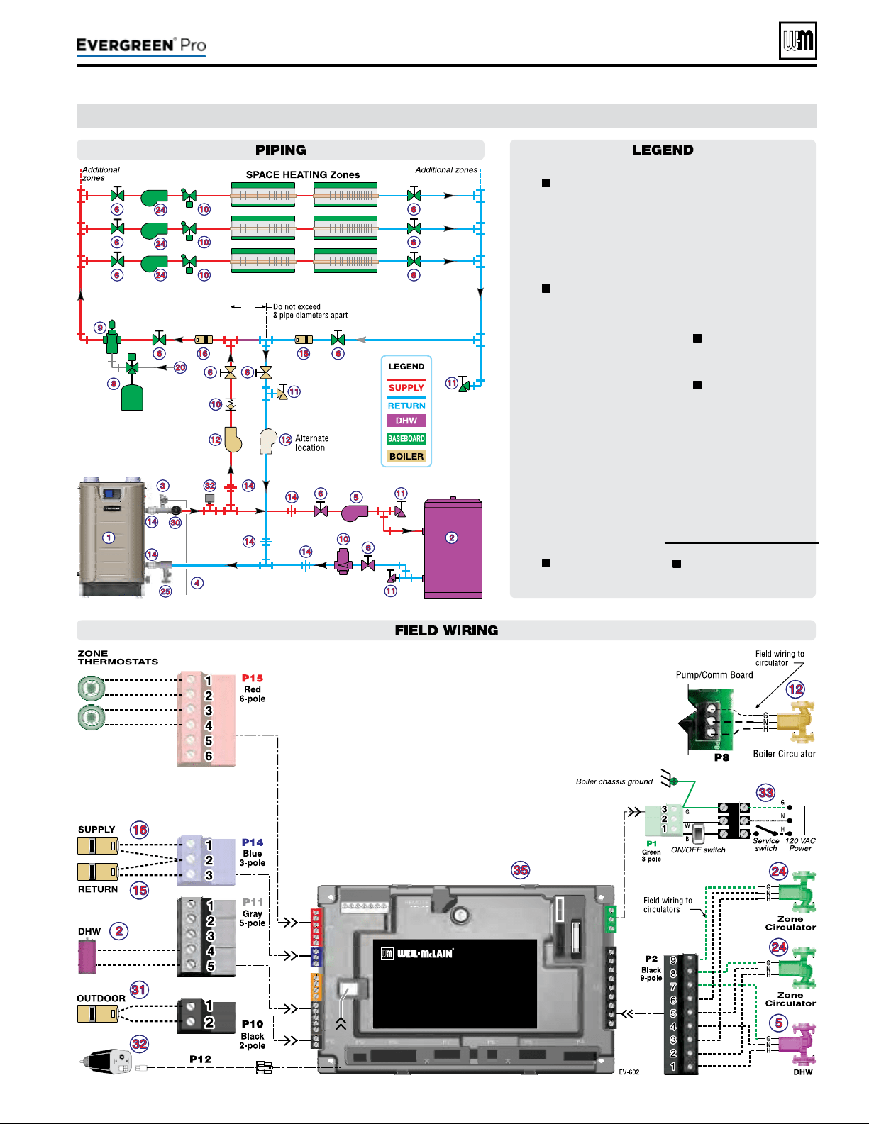
Part number 550-100-211/0122
– 71 –
220 /29 9/3 00 /39 9
B (continued)
1 Evergreen boiler.
2 Indirect water heater, if
used (domestic water
piping not shown) —
MUST be direct piped
to boiler to use default
control settings.
3
Relief valve, supplied
with boiler, eld piped
— MUST be piped to
boiler supply connection
— see Figure6,page11
for information.
4 Relief valve pip-
ing to drain.
5 DHW circulator.
6 Isolation valves.
8 Expansion tank.
9 Air separator.
10 Flow/check or spring
check valves.
11 Purge/drain valves.
12
Boiler circula-
tor, supplied with
boiler, eld piped.
14 Unions as needed
for service.
15 Return tempera-
ture sensor.
16 Supply tempera-
ture sensor.
20 Make-up water supply.
24 Zone circulators.
25
Boiler drain
valve, supplied with
boiler, eld piped.
30
Pressure/temperature
gauge, supplied with
boiler, eld piped.
31 Outdoor sensor.
32 Low water cut-o.
33 120VAC power to
boiler — see page53.
35 EVG Control module.
= Items supplied with
boiler — all other items
supplied by installer.
2-or3-ZoneSPACE H EATING(Circulatorswithoutcirculatorrelays)|DHW
(Direct-piped)
Part number 550-100-211/0122
– 72 –
C
Multi-zoneSPACE H EATING(Zonevalves+WMZVcontroller)|DHW
(Direct-piped)
EVG
(in order of WiZArd sequences)
RED — vAlue must be set or verified
d — defAult AcceptAble; chAnge only
if desired
BOILER SET TI NGS
BOILER MODEL
Verifymodelnumberiscorrect
WWSDTEMP
Default(70°F)orasrequired
HIGHALTITUDE
Settoaltitudeifover2,000feet
(Assign to PRIORITY 1)
WHATISTHEUSEOFINPUT/OUTPUT1?
HEAT/DHWDEMAND
WHATPRIORITYISINPUT#1?
select
PRIORITY1
WHATSYSTEMTYPEISINPUT/OUTPUT1?
DHW(D)
TARGETMODSENSOR
BOILEROUT(D)
TARGETADJUST
NONE(D)
SUPPLYMAX
D (or change if desired)
RUNBOILERPUMP?
NO(D)
RUNAUXPUMP/OUTPUT?
D (not applicable)
IN PU T/OUT PU T 2 (Assign to PRIORITY 2)
WHATISTHEUSEOFINPUT/OUTPUT2?
HEAT/DHWDEMAND
WHATPRIORITYISINPUT#2?
PRIORITY2
WHATSYSTEMTYPEISINPUT/OUTPUT2?
Selectcorrectsystemtype
TARGETMODSENSOR
SYSTEMSUPPLY(D)
TARGETADJUST
ODT(D)
(outdoor sensor must be installed)
SUPPLYMAX
D (or change if desired)
SUPPLYMIN
D (or change if desired)
ODRESETMAX
D (or change if desired)
ODRESETMIN
D (or change if desired)
BOOSTTIME
D (or change if desired)
RUNBOILERPUMP?
YES(D)
RUNAUXPUMP/OUTPUT?
D (not applicable)
IN PU T/OUT PU T 3 (Not used)
WHATISTHEUSEOFINPUT/OUTPUT3?
NONE
P1MAXONTIME
D (or change if desired)
P2MAXONTIME
D (or change if desired)
P2MINONTIME
D (or change if desired)
P3MINONTIME
D (not applicable)
ENTERTIME,DATEANDMAINTENANCEINFORMATIONASPROMPTED
Boiler Model, Altitude and Fuel Type are critical
settings.
Failure to set correctly could result in severe
personal injury, death or substantial property damage.
Incorrect setup or piping can result in severe personal
injury, death or substantial property damage.
Use primary/secondary piping or equivalent ONLY. Do
notusedirect-connectsystempiping.
Verify that the correct system type is selected on the con-
trol and that operating temperature settings are suitable
for the system. System and structural damage can occur
if temperatures are too high.
y Space heating with multiple zones.
y Zoning with zone valves.
DO NOT use 3-wire zone
valves — the voltage on the valve end switch will dam-
age the EVG control. Use only 4-wire zone valves with
isolated end switches.
y DHW piped directly to the boiler.
y DHW priority — space heating is disabled during call
for heat from water heater.
y See the table at right for required and optional settings.
y e sequence in the table follows the WIZARD.
y If not using the WIZARD, follow instructions elsewhere
in this manual to enter the settings manually.
y e system circulator is wired to OUTPUT2. It will
be activated on any call for heat from a zone valve end
switch.
Provide an external relay and external power
to any circulator if its load rating exceeds 2.2
amps FLA, 3.6amps locked rotor, or 16.4 amps
in rush.
y Piping must be primary/secondary as shown.
y DHW circulator must be selected to handle the pressure
drop through the boiler, water heater and piping. DHW
circulator supplied by installer.
y For some large indirect water heaters, the required ow
rate may require piping the water heater dierently.
y e control settings in table at right provide DHW
priority — space heating will be discontinued during
a call for DHW.
y Zone valves and system circulator supplied by installer.
For alternate zone wiring using a zone controller, see
page61.
y A by-pass pressure regulator is recommended when
used in a zone valve system as shown in this express
setup.
BOILER
y Boiler circulator shipped loose with boiler.
y Follow all instructions in this manual for piping boiler
and system.
Note1: IfDHWisnotused, set the USE of INPUT/OUTPUT1
to NONE. Keep all other wiring as shown at right and
follow all settings given above for PRIORITY2.
220 /29 9/3 00 /39 9
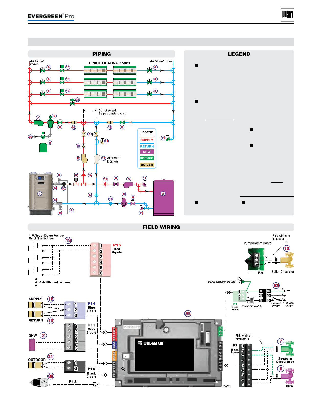
Part number 550-100-211/0122
– 73 –
220 /29 9/3 00 /39 9
C (continued)
1 Evergreen boiler.
2 Indirect water heater, if
used (domestic water
piping not shown) —
MUST be direct piped
to boiler to use default
control settings.
3
Relief valve, supplied
with boiler, eld piped
— MUST be piped to
boiler supply connection
— see Figure6,page11
for information.
4 Relief valve pip-
ing to drain.
5 DHW circulator.
6 Isolation valves.
7 System circulator.
8 Expansion tank.
9 Air separator.
10 Flow/check or spring
check valves.
11 Purge/drain valves.
12
Boiler circula-
tor, supplied with
boiler, eld piped.
13 Zone valves.
14 Unions as needed
for service.
15 Return tempera-
ture sensor.
16 Supply tempera-
ture sensor.
20 Make-up water supply.
21 By-pass pressure
regulator, REQUIRED
for zone valve systems.
25
Boiler drain
valve, supplied with
boiler, eld piped.
30
Pressure/temperature
gauge, supplied with
boiler, eld piped.
31 Outdoor sensor.
32 Low water cut-o.
33 120VAC power to
boiler — see page53.
35 EVG Control module.
= Items supplied with
boiler — all other items
supplied by installer.
Multi-zoneSPACE H EATING(Zonevalves+WMZVcontroller)|DHW
(Direct-piped)
Part number 550-100-211/0122
– 74 –
Figure72 Evergreen control settings available in BASIC MODE (see Advanced Manual for ADVANCED MODE settings)
Figure73 System types available in BASIC MODE (each option shown with factory settings)
AvailablesettingsfromCONTRACTORMENU
BoilerSettingsMenu Priority2menu AssignInputsmenu
y Boiler Model y Inputs Assigned (non-selectable)
Input1:TT1
y Control Type y System Type y Priority 1, 2 or 3
y High Altitude y Target Mod Sensor (non-selectable) y Source (TT1 or 0-10v)
y LP Gas y Target Adjust (non-selectable) y AUX PUMP/OUTPUT
y ODT Sensor Exempt y Supply Max y O
y Manual Reset High Limit Temp y Supply Min (not available for DHW) *
y WWSD Temp y OD Reset Max (or Volts for Max) *
Input2:TT2andInput3:TT3
y Adjust Outdoor y OD Reset Min (or Volts for Min) * y Priority 1, 2 or 3
y Circulator Exercising y Boost Time * y AUX PUMP/OUTPUT
y Freeze Protect Circs y O
y Reset Factory Default
Priority3menu
y Inputs Assigned (non-selectable)
Diagnosticsmenu
Priority1menu
y System Type
y See Figure80,page80 for details.
y Inputs Assigned (non-selectable) y Target Mod Sensor (non-selectable)
y System Type y Target Adjust (non-selectable)
MaintenanceInfomenu
y Target Mod Sensor (non-selectable) y Supply Max
y See Figure85,page85 for details.
y Target Adjust (non-selectable) y Supply Min (not available for DHW) *
y Supply Max y OD Reset Max (or Volts for Max) *
SetDateandTimemenu
y Supply Min (not available for DHW) * y OD Reset Min (or Volts for Min) *
y See Figure85,page85 for details.
y OD Reset Max (or Volts for Max) * y Boost Time *
y OD Reset Min (or Volts for Min) * * ese items only appear in the menus if Target Adjust is active.
y Boost Time *
SystemType
8-Character
Abbreviation
3-Character
Abbreviation
Supply Max
°F
OD Reset
Min °F
Supply
Min °F
OD Reset
Max °F
Run
Boiler Pump
Run AUX
PUMP/
OUTPUT
Fan-coil FAN-COIL
FCL 180 0 140 70 YES YES
Finned Tube
Baseboard
FIN BASE
FTB 180 0 130 70 YES YES
Cast Iron Baseboard IRONBASE
CIB 180 0 120 70 YES YES
Cast Iron Radiators RADIATOR
CIR 180 0 120 70 YES YES
Radiant - slab on grade RAD SLAB
RSG 120 0 80 70 YES YES
Radiant - thin slab RAD SLAB
RTS 140 0 80 70 YES YES
Radiant - below oor
(staple up)
RADFLOOR
RSU 160 0 90 70 YES YES
Radiant - above oor
(sleeper system)
RADFLOOR
RAF 140 0 90 70 YES YES
Domestic Hot Water DOMESTIC
DHW 180 N/A N/A N/A NO NO
Custom (user dened)
XXXXXXXX
(user input)
rst three of
user input
180 0 70 70 YES YES
220 /29 9/3 00 /39 9

Screensshownabovearetypicalonly.
Actualscreensdependoncontrol
settingschosen.
Part number 550-100-211/0122
– 75 –
220 /29 9/3 00 /39 9
BoilerModel,AltitudeandFuelTypearecriti-
cal
settings.Failure to set correctly could result in
severe personal injury, death or substantial property
damage.
1. Access contractor menus by pressing and holding the UP and
DOWN arrow keys at the same time for 7 seconds.
2. See the following pages for explanations of control setting
options.
MENUITEM PURPOSE
More
information
USER MODE
y e default for this setting is BASIC mode. Screens shown
in this manual assume the USER MODE is set to BASIC. For
advanced features available in ADVANCED mode, see the
Evergreen Advanced Manual.
BOILER
SETTINGS
y Set/change boiler model, control type,
high altitude setting, ODT sensor require-
ment, manual reset, high limit and WWSD
temperature settings, outdoor sensor temp
adjustment, circulator exercising, freeze
protection setup, and restore to factory
default option.
See page 76
PRIORITY 1
y ese settings control operating tempera-
tures and behaviors for systems that are
assigned to “PRIORITY 1.”
See page 77
PRIORITY 2
y ese settings control operating tempera-
tures and behaviors for systems that are
assigned to “PRIORITY 2.”
See page 77
PRIORITY 3
y ese settings control operating tempera-
tures and behaviors for systems that are
assigned to “PRIORITY 3.”
See page 77
ASSIGN INPUTS
y ese settings assign Priority 1, 2 or 3 to
each of the three inputs to the Evergreen
control.
See page 78
DIAGNOSTICS
y Use to review current and historical infor-
mation including previous lockouts.
See page 80
MAINTENANCE
INFO
y Used to set contractor contact information,
boiler information and maintenance dates.
See page 85
SET TIME &
DATE
y Use to set date and time — important since
fault occurrences are date/time stamped.
None
Figure74 Evergreen control menu access — accessing contractor menus
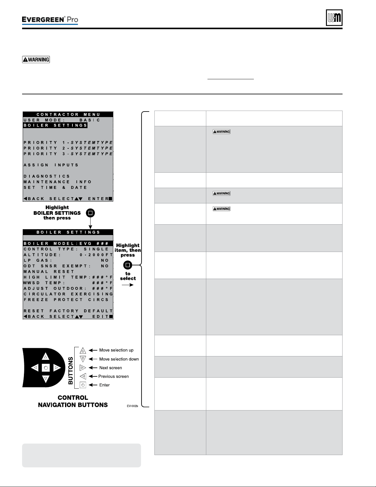
Screensshownabovearetypicalonly.
Actualscreensdependoncontrol
settingschosen.
Part number 550-100-211/0122
– 76 –
BoilerModel,AltitudeandFuelTypearecriti-
cal
settings.Failure to set correctly could result in
severe personal injury, death or substantial property
damage.
1. Access contractor menus by pressing and holding the UP and
DOWN arrow keys at the same time for 7 seconds.
2. See Figure74,page75 for the screen sequences up to the
CONTRACTOR menu.
MENUITEM DESCRIPTION
BOILER MODEL
y
MUST be set to correct model.
y Check the boiler model against the model listed on the
boiler’s rating plate. Change the selection to the correct
model if not. Also verify the model number on the
Evergreen control display at power-up. Failure to correct
would result in severe personal injury, death or substan-
tial property damage.
CONTROLTYPE
y Select single, master or shadow. Must be set to Single for
basic mode.
HIGHALTITUDE
y
MUST be set to correct value if altitude over
2,000feet — values selectable in 500 feet increments.
LPGAS
y
MUST be correct — YES if LP Gas is used or NO
if natural gas is used. Follow screen instructions to change
if necessary.
ODTSENSOR
EXEMPT
y Select YES only if boiler is exempt from the requirement
for outdoor reset operation stipulated in Section 303 of
the 2007 Energy Act. See information provided elsewhere
in this manual.
MANUALRESET
HIGHLIMITTEMP
y If boiler outlet water temperature exceeds this tempera-
ture, the Evergreen control will shut down the boiler and
enter lockout. Changing this setting is NOT recom-
mended.
WWSDTEMP
y WWSD stands for warm weather shut down. It means
the boiler will not be allowed to fire if the outside
temperature is greater than the WWSD setting.
When the boiler is kept off because the outside tem-
perature is above WWSD, the graphic display will show
WWSD, and the boiler will remain in standby until the
outside temperature drops below WWSD temperature.
WWSD does not apply to DHW systems.
e outdoor sensor must be installed to use this function.
ADJUSTOUTDOOR
y Use this setting to calibrate the outdoor sensor when needed
to compensate for variations in lead length or other factors
that could aect total resistance in sensor circuit.
CIRCULATOR
EXERCISING
y For each circulator, select whether you want the control
to automatically start the circulator and run for 10 sec-
onds for each 72-hour period of inactivity.
FREEZEPROTECT
CIRCS
y is function automatically res the boiler at low re and
starts the circulators chosen if the heat exchanger sensors
detect a temperature less than 45 °F. Burner is turned on
if temperature drops below 40 °F. Circulators and burner
turn o when the temperature rises above 48 °F.
RESETFACTORY
DEFAULTS
y Use this function to restore all control settings to fac-
tory default values — will require complete restart and
setup of control aer resetting. Record information from
the MAINTENANCE screen and any history informa-
tion that may be of use in the future. ALL stored data is
eliminated when reset to defaults except for boiler model
number.
Figure75 Evergreen BASIC mode BOILER SETTINGS options (USER MODE must be set to BASIC)
220 /29 9/3 00 /39 9

Figure76 Evergreen BASIC mode PRIORITY options (USER MODE must be set to BASIC)
Screensshownabovearetypicalonly.
Actualscreensdependoncontrol
settingschosen.
Part number 550-100-211/0122
– 77 –
220 /29 9/3 00 /39 9
BoilerModel,AltitudeandFuelTypearecriti-
cal
settings.Failure to set correctly could result in
severe personal injury, death or substantial property
damage.
1. Access contractor menus by pressing and holding the UP and
DOWN arrow keys at the same time for 7 seconds.
2. See Figure74,page75 for the screen sequences up to the
CONTRACTOR menu.
MENUITEM DESCRIPTION
INPUTS ASSIGNED
y Lists all the inputs already assigned to this PRIORITY.
Inputs will be listed as 1, 2, 3.
y Shows NONE if there are no inputs assigned to this
priority .
SYSTEM TYPE
y Select the system type for this PRIORITY, based
on the heating terminal units in the system (see
Figure73,page74). Use the CUSTOM selection to set the
control for a dierent system type. e factory preset val-
ues for SUPPLY MAX, SUPPLY MIN, OD RESET MAX
and OD RESET MIN are chosen based on the normal
best setting for the terminal units.
TARGET MOD
SENSOR
y Choose SYSTEM SUPPLY or BOILER OUT to deter-
mine which will be the primary temperature sensor. e
control will modulate boiler input to reach the TARGET
temperature. (Default is System Supply.) If system sensors
are not used, boiler defaults to using heat exchanger outlet
sensor in place of system sensor.
y Not adjustable in Basic Mode, see Advanced Manual for
information on adjusting this parameter.
TARGET ADJUST
y Select how target temperature is calculated by control:
NONE (no reset, xed target temperature), 0-10V (target
temperature based on analog input from remote source),
ODT (outdoor reset operation; default setting).
y Not adjustable in Basic Mode, see Advanced Manual for
information on adjusting this parameter.
SUPPLY MAX
y Set SUPPLY MAX to the required supply water tempera-
ture for the system at design maximum heat loss (typically
180 °F for nned tube baseboard on new installations.)
SUPPLY MIN
y SUPPLY MIN should equal the desired minimum supply
water temperature for the system.
y is line is not shown on priorities congured as DHW
system type or Heating system type, if outdoor tempera-
ture sensor not used. See Advanced Manual for informa-
tion on adjusting this parameter .
OD RESET MAX
(Not shown for
Priority 1 by default)
y OD RESET MAX is the outdoor temperature at which the
target temperature reaches its minimum (SUPPLY MIN).
y is line is not shown on priorities congured as DHW
system type or Heating system type, if outdoor tempera-
ture sensor not used. See Advanced Manual for informa-
tion on adjusting this parameter .
OD RESET MIN
y OD RESET MIN means the outdoor temperature at
which the target temperature reaches its maximum value
(SUPPLY MAX).
y OD RESET MIN should equal the ODT (outdoor design
temperature) for the installation’s location.
y is line is not shown on priorities congured as DHW
system type or Heating system type, if outdoor tempera-
ture sensor not used. See Advanced Manual for informa-
tion on adjusting this parameter .
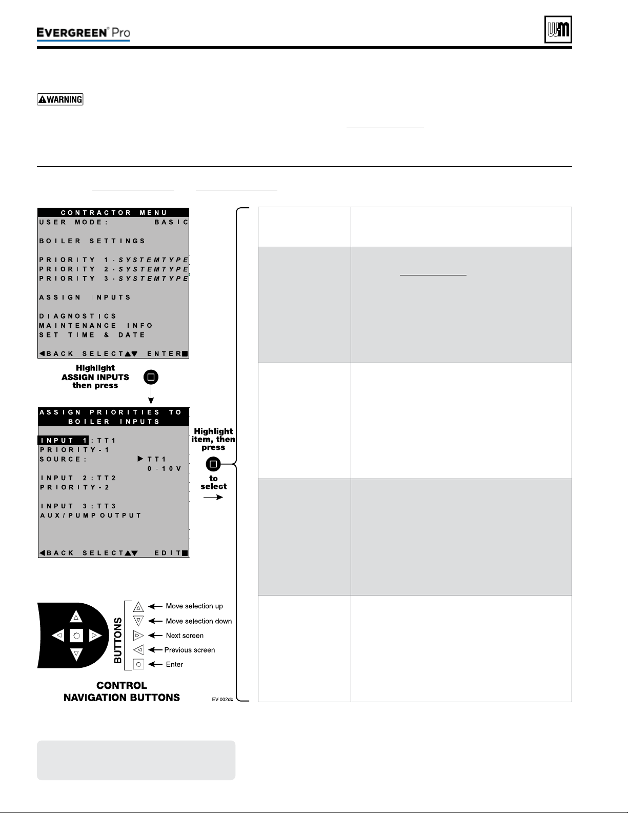
Figure77 Evergreen BASIC mode ASSIGN INPUT options (USER MODE must be set to BASIC) — see
Figure 78, page 79 and Figure 79, page 79 for explanation of AUX PUMP/OUTPUT settings
Screensshownabovearetypicalonly.
Actualscreensdependoncontrol
settingschosen.
Part number 550-100-211/0122
– 78 –
BoilerModel,AltitudeandFuelTypearecriti-
cal
settings.Failure to set correctly could result in
severe personal injury, death or substantial property
damage.
1. Access contractor menus by pressing and holding the UP and
DOWN arrow keys at the same time for 7 seconds.
2. See Figure74,page75 for the screen sequences up to the
CONTRACTOR menu.
MENUITEM DESCRIPTION
Overview
y ere are three priority levels dened by the settings
chosen in Figure76,page77.
y For DHW priority, make sure PRIORITY 1 is dened
for a DHW system.
y If DHW priority is required and analog input (0-10v
remote modulation) is used for space heating, wire the
DHW aquastat to Input 2 (TT2) and assign INPUT2
as PRIORITY 1 and INPUT1 as PRIORITY2 with
SOURCE set to 0-10V.
INPUT 1
y Assign priority (system type) for INPUT 1 — options are:
y PRIORITY 1 — assigns INPUT1 to PRIORITY1 system.
y PRIORITY 2 — assigns INPUT1 to PRIORITY2 system
y PRIORITY 3 — assigns INPUT1 to PRIORITY3 system
y AUX PUMP/OUTPUT
y OFF
y NOTE: For INPUT1 only, select SOURCE = TT1 for
thermostat input or 0-10V if analog input is required.
INPUT 2
y Assign priority (system type) for INPUT 2 — options are:
y PRIORITY 1 — assigns INPUT2 to PRIORITY1 system.
y PRIORITY 2 — assigns INPUT2 to PRIORITY2 system
y PRIORITY 3 — assigns INPUT2 to PRIORITY3 system
y AUX PUMP/OUTPUT
y OFF
INPUT 3
y Assign priority (system type) for INPUT 3 — options are:
y PRIORITY 1 — assigns INPUT3 to PRIORITY1 system.
y PRIORITY 2 — assigns INPUT3 to PRIORITY2 system
y PRIORITY 3 — assigns INPUT3 to PRIORITY3 system
y AUX PUMP/OUTPUT
y OFF
220 /29 9/3 00 /39 9
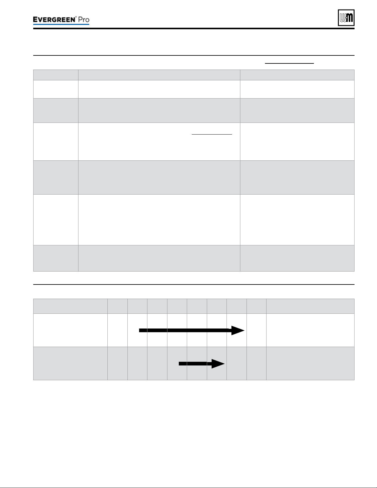
Part number 550-100-211/0122
– 79 –
220 /29 9/3 00 /39 9
(continued)
Figure78 AUX PUMP/OUTPUT operation (accessed in ASSIGN INPUTS menu – see Figure 77, page 78)
Option Activationconditions Suggesteduses
ALWAYSON
y Output is always energized whenever the control is powered.
y Hot loop for seasonal boilers that are manually
shut down at end of season and started up at
start of heating season.
EXTERNAL
SWITCH
y e output is energized on closure of an external switch wired to this
input and is de-energized when the external switch opens.
y Hot loop for boilers whose CH is manually
shut down at end of season and started up at
start of heating season, but remain available for
local calls (DHW, etc.).
OUTDOOR
BELOW WWSD
y is output is energized only when outdoor temperature is below the
WWSD setting (see BOILER SETTINGS menu, Figure75,page76).
y is setting is non-selectable if WWSD is set to OFF or ODT is not
connected at initial boiler power. If Outdoor Below WWSD is already
chosen and WWSD is later set to OFF, Outdoor Below WWSD will
behave as Always On.
y Hot loop for boilers whose CH is automati-
cally shut down based on outdoor temperature
(inferred heat loss), but remain on for local
calls (DHW, etc.).
ANYTTINPUT
y e assigned output is energized if there is an input closure on this boiler.
y e assigned output will de-energize once there are; no input on this
boiler, post-purge has nished and post-pump time has expired.
y If the closed input is congured for a heat demand, its output will de-
energize aer post-purge and post-pump.
y Energize a system pump relay if pump must
run during all heating calls.
ANYTTINPUT
BYITSPRIORITY
SETTINGS
y e assigned output is energized:
• If there is an input closure on this boiler.
. . . and . . .
• RUN AUX PUMP/OUTPUT is set to YES for the priority as-
signed to the closed input.
y e assigned output will de-energize once there are no input closures
on any of the network boilers, post-purge has nished, and post-pump
time has expired.
y Energize a system pump relay if pump must
run only on some heat calls (such as systems
with locally-connected DHW heating).
BURNER
DEMAND
y e assigned output is energized when the boiler receives a call for
heat and starts to pre-purge.
y e assigned output is de-energized once the burner is o and post-
purge is complete.
y Use for interlocking with combustion air
damper, ow switch, etc.
Figure79 AUX PUMP/OUTPUT operation — start, run and stop, based on boiler status
Option
Standby
TT
Closed
Pre-Pump Pre-Purge
Burner
Running
Post-
Purge
Post-
Pump
Standby
Comments
ANYTTINPUT
OR
ANYTTINPUTBYITS
PRIORITYSETTINGS
o
ON
o
y See Figure78 for explanation of
differences between the ANY TT
INPUT options.
BURNERDEMAND o o o
ON
o o
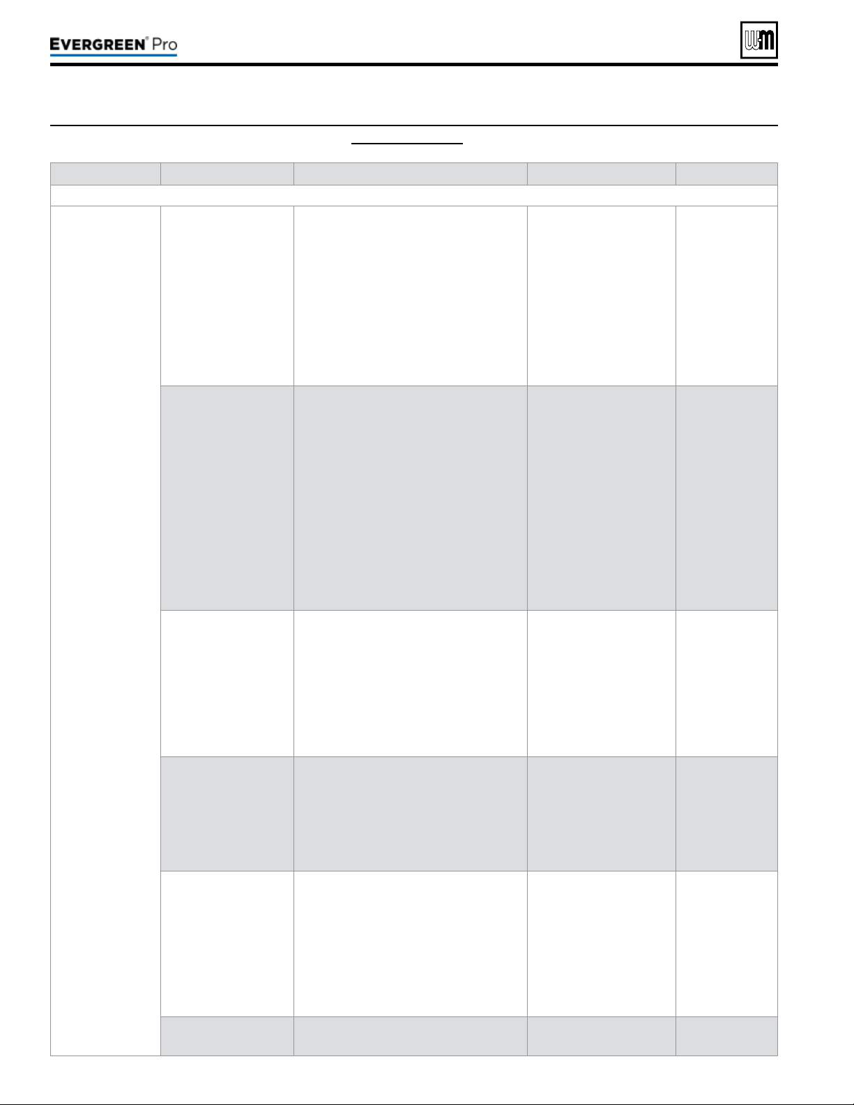
Figure80 DIAGNOSTICS menu navigation (see Figure 71, page 67 for access information)
Part number 550-100-211/0122
– 80 –
Menus Nextscreen Nextscreen Nextscreen Nextscreen
Follow information at the bottom of each screen to navigate to next/previous screen or enter/save data
DIAGNOSTICS TEMPERATURES STATUS: ##########
BOILER OUT1: ###
ºF
BOILER OUT2: ###
ºF
BOILER IN: ###
ºF
SYSTEM SUPPLY: ###
ºF
SYSTEM RETURN: ###
ºF
FROM SENSOR: ######
FLUE 1: ###
ºF
FLUE 2: ###
ºF
OUTDOOR TEMP: ###
ºF
FROM SENSOR: ######
See following pages for details.
INPUTS STATUS: ##########
INPUT1: ######## (8-character system type)
INPUT2: ######## (8-character system type)
INPUT3: ######## (8-character system type)
0–10v: ##. #V
LINKED TO MASTER: ###
DEMAND OF MASTER: ###
MANUAL LIMIT: ######
AUTO LIMIT: ######
LOW WTR CUTOFF: ######
AIR P-SWITCH: ######
CLOSURE SWITCH: ######
BLOWER SPEED: ####RPM
FLAME SIGNAL: ###
See following pages for details.
OUTPUTS STATUS: ##########
GAS VALVE: ###
CIRC OUTPUT 1: ###
CIRC OUTPUT 2: ###
CIRC OUTPUT 3: ###
BOILER CIRC: ###
BLOWER SIGNAL: ###%
ADD’L HEAT DEMANDS: ###
ALARM: ###
See following pages for details.
RUNTIME BURNER TIME: ###HR
ROTATE TIME: ###DAYS
INPUT1 TIME: ###HR
INPUT2 TIME: ###HR
INPUT3 TIME: ###HR
NETWORK TIME: ###HR
IGNITION COUNT: ###
See following pages for details.
MASTER-SHADOW COMM
(shows on shadow boilers only)
Boiler ID: ############
Linked to Master: ###
Boilers on Network: #
Requested to Run: ###
Type: ######-##
Requested Mod Rate: ###
Max Boiler Temp: ###
ºF
Boiler ON Di: ##
ºF
Boiler OFF Di: ##
ºF
See following pages for details.
NETWORK BOILERS
(shows on master boilers only)
Shows ring rate, boiler temperature, active priority,
with system type and sequence order of all boilers on the
network.
See following pages for details.
220 /29 9/3 00 /39 9

(continued)
Figure81 DIAGNOSTICS menu navigation, continued (see Figure 71, page 67 for access information)
Part number 550-100-211/0122
– 81 –
220 /29 9/3 00 /39 9
Menus Nextscreen Nextscreen Nextscreen Nextscreen
Follow information at the bottom of each screen to navigate to next/previous screen or enter/save data
DIAGNOSTICS (cont.) NETWORK INPUTS
(shows on master boilers only)
Shows input status of all network boiler inputs.
SOFTWARE VERSIONS DISPLAY WM#.##
MAIN MICRO WM#.##
SECOND MICRO WM#.##
See following pages for details.
PAST ERRORS CONTROL FAULTS: ###
IGNITION RETRIES: ###
See following pages for details.
MANUAL RESET CNT: ### See following pages for details.
AUTO RESET CNT: ### See following pages for details.
LOCKOUT HISTORY 1
LOCKOUT HISTORY 2
LOCKOUT HISTORY 3
LOCKOUT HISTORY #
FAULT NAME: ####
FAULT TYPE: ####
TIME: HH:MM AM
DATE: MM/DD/YY
STATUS: ########
TEMPERATURES
INPUTS
OUTPUTS
TEMPERATURES
INPUT STATUS
OUTPUT STATUS
MANUAL TEST MODE
(Single boiler or network
Shadow boiler)
STATUS: ########
INPUTS: ####
TARGET: ###
ºF or “%” for network
MODULATION: ########
BOILER OUT: ###
ºF
BOILER IN: ###
ºF
SYSTEM SUPPLY: ###
ºF
SYSTEM RETURN: ###
ºF
FLUE: ###
ºF
OUTDOOR: ###
ºF
BLOWER SIGNAL: ###%
BLOWER SPEED: ###RPM
FLAME SIGNAL: ###
FORCE RATE: AUTO
See following pages for details.
MANUAL RESET PRESS ENTER TO RESET THE FOLLOWING
ERROR (SCREEN SHOWS A LIST OF ERRORS)
See following pages for details.
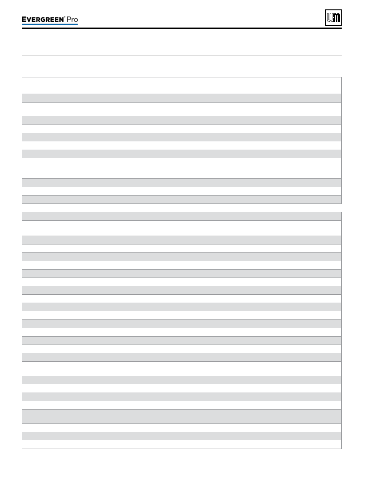
Figure82 DIAGNOSTICS menu details (see Figure 71, page 67 for access information)
(continued)
Part number 550-100-211/0122
– 82 –
Menu/Item Comment
Temperatures
Status
Current operating status of the boiler. Prepurge, Ignition, Name of the system Type being satised, post purge,
Warm Weather Shut down, Trouble
Boiler Out1
Temperature of the rst sensing element of the boiler’s heat exchanger outlet sensor
Boiler Out2
Temperature of the second s
ensing element of the boiler’s heat exchanger outlet sensor
Boiler In
Temperature of the boiler’s heat exchanger inlet sensor
System Supply
Temperature of the system water aer the boiler loop
System Return
Temperature of the system water returning to the boiler loop
From Sensor
Displays where System Supply/Return values are being read from. Most relevant when using multiple sensors
connected to the same Master Boiler Network. When Shadow boilers are connected, this will specify which boiler
it is reading.
Flue1
Temperature of the rst sensing element of the boiler’s ue gas sensor
Flue2
Temperature of the second sensing element of the boiler’s ue gas sensor
Outdoor
Temperature of the remote outdoor air temperature sensor
Inputs
Status
Current operating status of the boiler. Prepurge, Ignition, Name of the system Type being satised, post purge,
Warm Weather Shut down, Trouble
Input 1
Call for heat status on Input 1 (Input 1 can be TT1 or 0-10VDC input)
Input 2
Call for heat status on Input 2
Input 3
Call for heat status on Input 3
0–10V
Voltage input for target adjust or modulation for single boiler
Linked to Master
For Multiple Boiler Networks. Shows if current control is connected to Master boiler
Demand of Master
For Multiple Boiler Networks. Shows if the Master boiler is calling this boiler heat demand
Manual Limit
External manual limit on low voltage terminal strip
Auto Limit
External auto limit on low voltage terminal strip
Low Wtr Cutoff
Low water cuto device (inside boiler jacket)
Air P-Switch
Limit device (inside boiler jacket) that will shut o the boiler if ue pressure becomes too high
Closure Switch
P7 jumper circuit closed or open (ow switch, CAD, etc.)
Blower Speed
Feedback from blower sensor
Flame Signal
Number indicating the presence and quality of the ame used to shut down or boost the boiler
Outputs
Status
Current operating status of the boiler. Prepurge, Ignition, Name of the system Type being satised, post purge,
Warm Weather Shut down, Trouble
Gas Valve
Control’s gas valve circuit status
Circulator 1
Control’s circulator 1 relay status
Circulator 2
Control’s circulator 2 relay status
Circulator 3
Control’s circulator 3 relay status
Boiler Circ
Boiler’s circulator
Blower Signal
Control’s signal controlling the blower speed
Additional Heat Demand
Additional heat demand contact status
Alarm
Alarm contact status
220 /29 9/3 00 /39 9
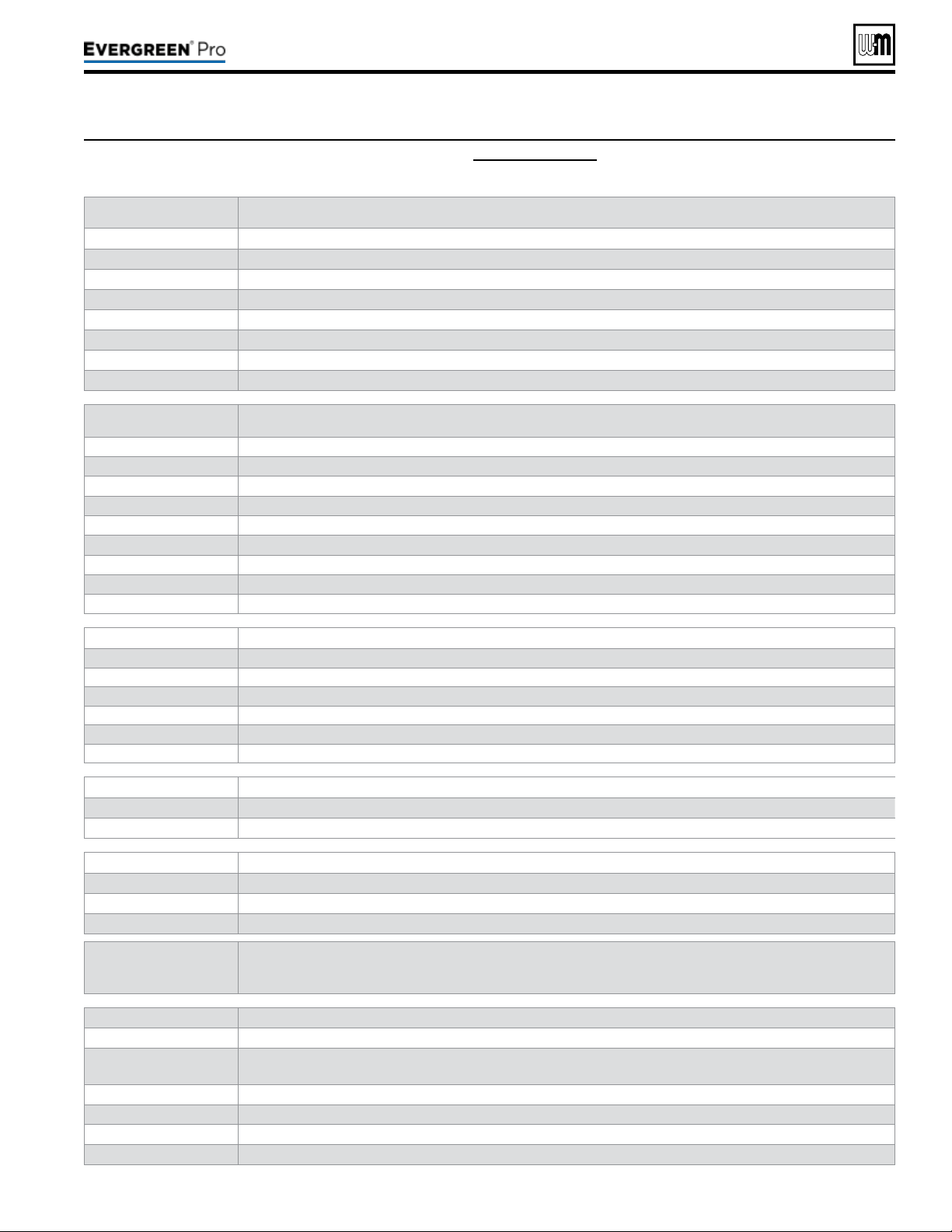
Figure83 DIAGNOSTICS menu details (continued) (see Figure 71, page 67 for access information)
Part number 550-100-211/0122
– 83 –
220 /29 9/3 00 /39 9
(continued)
Menu/Item Comment
RunTimes
Burner Time
Displays cumulative time the burner has been active (can be increased by user)
Rotate Time
Records the days of operation passed from the last time the Master boiler rotated the ring sequence.
Input 1 Time
Displays cumulative time that Input 1 has been closed (Or 0-10V ≥ 1 volt)
Input 2 Time
Displays cumulative time that Input 2 has been closed
Input 3 Time
Displays cumulative time that Input 3 has been closed
Network Time
Records time this boiler was running on a network call for heat generated by the Master boiler
Ignition Count
Displays total number of successful ignitions
Master-Shadow
Comm
Boiler ID
Displays boiler control type and ID number
Linked to Master
Shows if control is currently linked to a Master control
Boilers on Network
Shows number of boilers currently on network
Requested to Run
Shows if this control is being requested to satisfy a network call
Type
Shows whether the control is Network-P1, Network-P2, or NONE
Requested Mod Rate
Rate coming from the Master
Max Boiler Temp
Displays maximum allowable boiler temperature
Boiler On Diff
Temperature dierential from master boiler for network priorities
Boiler Off Diff
Temperature dierential from master boiler for network priorities
NetworkBoilers Formultipleboilersonly–SeeEVGAdvancedmanual
###%
Shows current rate of boiler
###F
Shows Boiler Out temperature of boiler
######
Shows priority being satised, updated based on active demand
######
Shows system type of call for heat, updated based on active demand
# OF #
Shows the sequence position of that boiler in all the boilers available
BLR#
Shows boiler number this data belongs to
NetworkInputs
Boiler number
Displays boiler number
Inputs
Displays input’s conguration and whether it is active. If input is active, it will be displayed in BOLD print
SoftwareVersions
Display Soware version of the microprocessor on the display circuit board
Main Micro Soware version of the main microprocessor on the control circuit board
Second Micro Soware version of the second microprocessor on the control circuit board
TORESETALL
HISTORYCOUNTERS
TOZERO:
To reset all history counters to zero: Enter the PAST ERRORS menu. en press and hold the le and right arrows
located below the control display. Hold for 5seconds. is will cause ALL history to be deleted. To maintain
history, reset counters individually.
PastErrors
Control Fault
Displays number of control faults
Ignition Retries
Displays cumulative ignition attempts. It is recommended that his be reset during yearly maintenance by holding
down the Le and Right arrows or by selecting this line and pressing the Enter button
Manual Reset Cnt
Displays number of manual reset lockouts since last cleared
Auto Reset Cnt
Displays number of auto reset lockouts since last cleared
Lockout History 1
Choose this to view the most recent error recorded
Fault Name
Displays the name of the fault that occurred

Figure84 DIAGNOSTICS menu details (continued) (see Figure 71, page 67 for access information)
Part number 550-100-211/0122
– 84 –
(continued)
Menu/Item Comment
Fault Type
Displays the type of fault that occurred
Time
Displays time that lockout occurred
Date
Displays date that lockout occurred
Status
Displays what the status of the boiler was at the time of the error
Temperatures
Choose this to view the Boiler Temperatures at the time of the error
Inputs
Choose this to view the status of the Boiler Inputs at the time of the error
Outputs
Choose this to view the status of the Boiler Outputs at the time of the error
Lockout History 2
Choose this to view the second most recent error recorded
Fault Name
Displays the name of the fault that occurred
Fault Type
Displays the type of fault that occurred
Time
Displays time that lockout occurred
Date
Displays date that lockout occurred
Status
Displays what the status of the boiler was at the time of the error
Temperatures
Choose this to view the Boiler Temperatures at the time of the error
Inputs
Choose this to view the status of the Boiler Inputs at the time of the error
Outputs
Choose this to view the status of the Boiler Outputs at the time of the error
Lockout History 3
Choose this to view the third most recent error recorded
Fault Name
Displays the name of the fault that occurred
Fault Type
Displays the type of fault that occurred
Time
Displays time that lockout occurred
Date
Displays date that lockout occurred
Status
Displays what the status of the boiler was at the time of the error
Temperatures
Choose this to view the Boiler Temperatures at the time of the error
Inputs
Choose this to view the status of the Boiler Inputs at the time of the error
Outputs
Choose this to view the status of the Boiler Outputs at the time of the error
ManualTestMode
Status Current operating status of the boiler. Prepurge, Ignition, Name of the system Type being satised, post purge,
Warm Weather Shut down, Trouble
Inputs Displays which inputs are presently calling for heat
Target Calculated target temperature based on outdoor temp or the max target if no ODR
Modulation Displays what sensor the boiler is using to modulate from. May also indicate reason for boiler rate self-limiting.
Boiler Out Temperature of the outlet sensor on the boiler heat exchanger
Boiler In Temperature of the inlet sensor on the boiler heat exchanger
System Supply Temperature of the system water aer the boiler loop
System Return Temperature of the system water returning to the boiler loop
Flue Temperature of ue gases
Outdoor Temperature of outdoor air
Blower Signal Control’s signal controlling the blower speed
Blower Speed Blower’s feedback to the control
Flame Signal Number indicating the presence and quality of the ame used to shut down or boost the boiler
Force Rate Used to manually force a rate during a call for heat. Choose auto for normal operation
ManualReset
Reset selected condition
220 /29 9/3 00 /39 9
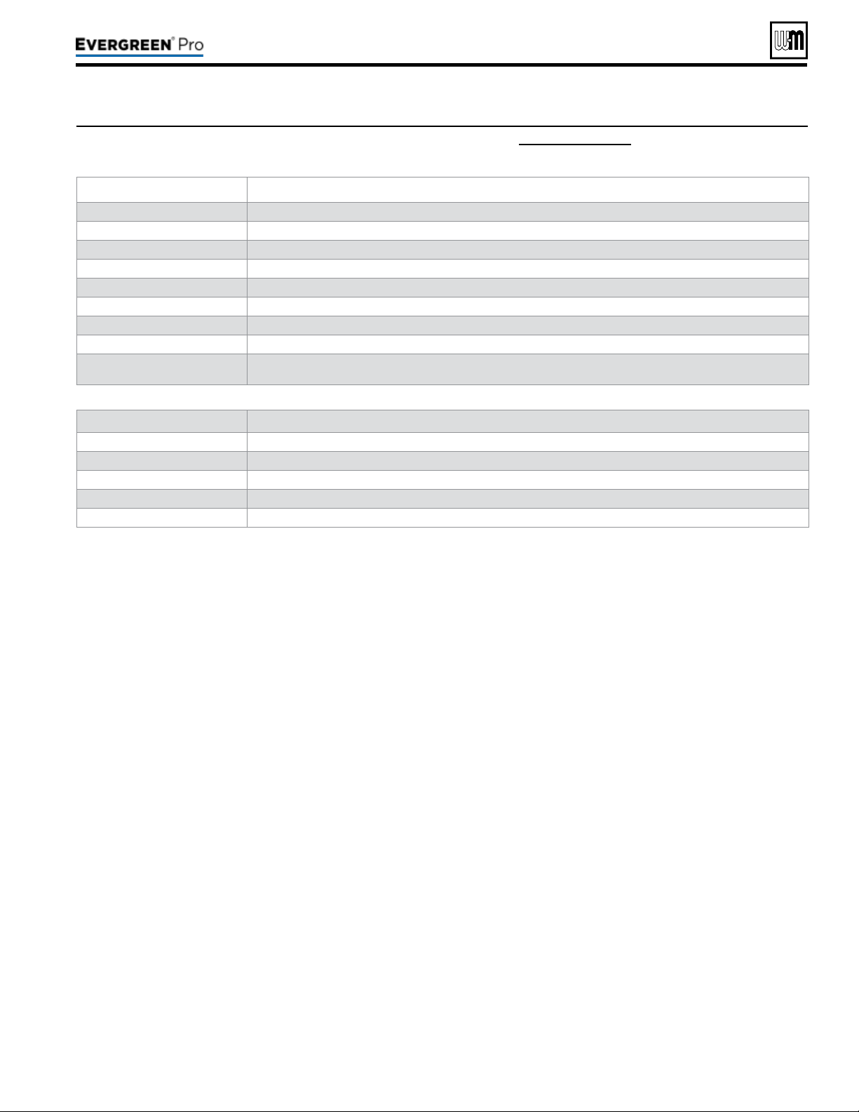
Part number 550-100-211/0122
– 85 –
220 /29 9/3 00 /39 9
Figure85 MAINTENANCE,DATEANDTIME menus — navigation (see Figure 71, page 67 for access information)
MAIN T ENAN CE INFO
1. Use this section to enter contractor’s information, CP number, install date and to enter an automatic notice for maintenance (de-
fault is 12 months). Because this shows on the display, it is an automatic means of notifying the homeowner of need for scheduled
maintenance by the technician. Select RESET REMINDER to reset for the next maintenance date.
SET T I ME AND DATE
1. Enter current date and time. is allows correct maintenance reminder timing and provides date and time stamp for lockout
histories on ERROR screen in Diagnostic Menu.
MaintenanceInfo
Comment
Name Contractor name to appear in maintenance reminders and during lockouts
Phone Contractor phone number
Model Displays the boiler model selected in the boiler setup
CP Number Enter the CP# of the boiler
Installed Enter the date the boiler was installed
Last Date Date automatically entered when Reset Reminder is chosen by contractor
Next Date Date automatically calculated when Reset Reminder is selected by contractor
Interval Settings Contractor selects maintenance reminder frequency based on service history
Reset Reminder Contractor selects this to update Last maintenance Date and Next Date. Homeowner uses this to ignore the
reminder and update only the Next Date.
SetTimeandDate
Ye a r Set year (homeowner or contractor)
Month Set month (homeowner or contractor)
Day Set day (homeowner or contractor)
Hour Set hour (homeowner or contractor)
Minute Set minute (homeowner or contractor)
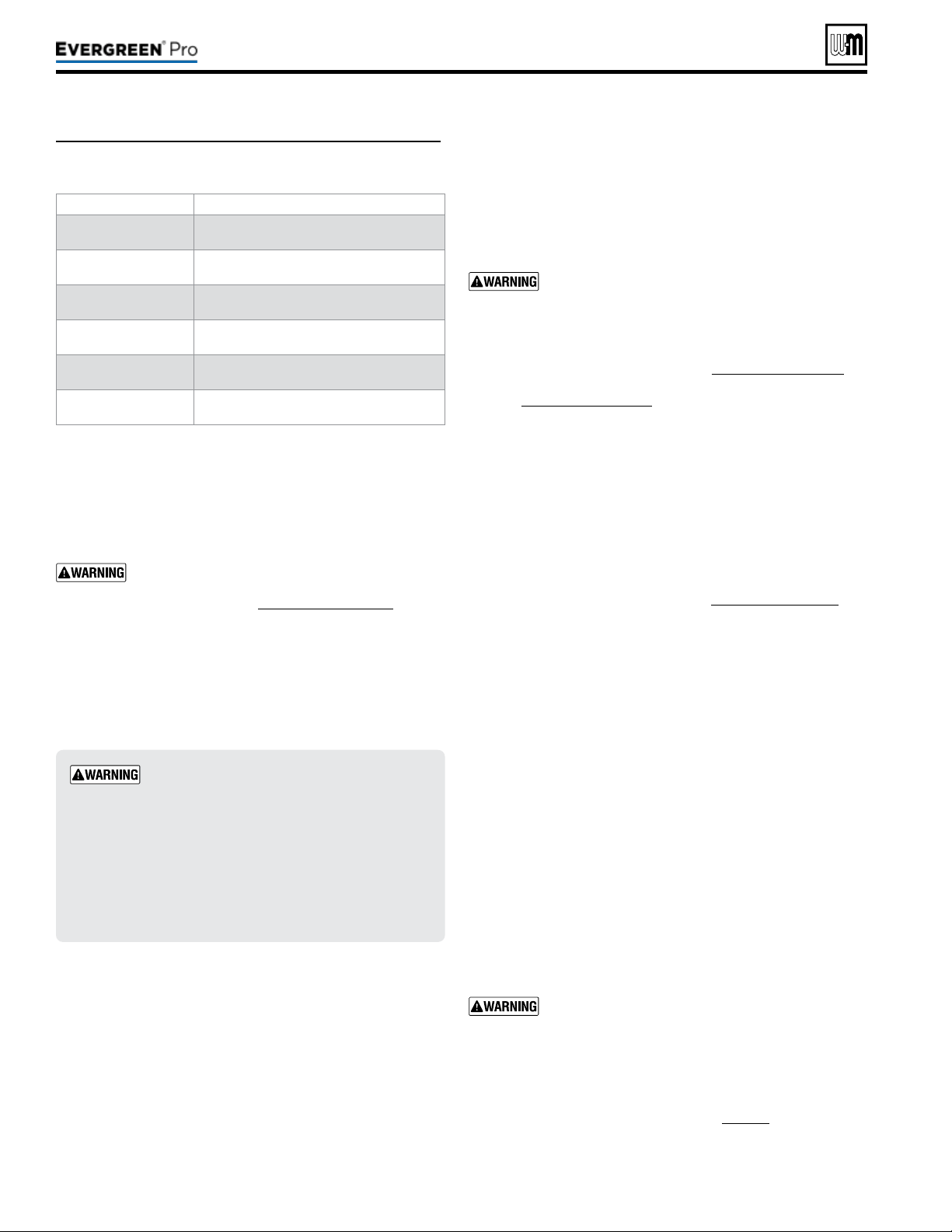
Part number 550-100-211/0122
– 86 –
Chlorideconcentrationrequirement
1. Filling with chlorinated fresh water should be acceptable since
drinking water chloride levels are typically less than 5 ppm.
2. Do not use the boiler to directly heat swimming pool or spa
water.
3. Do not ll boiler or operate with water containing chloride in
excess of 200ppm.
Verify that the water chemistry meets the limita-
tions and requirements of all other equipment in
the system.
Antifreeze
1. Use only antifreeze listed by Weil-McLain as suitable for use
with
Evergreen
®
Gas Boilers. See Figure111,page117 for
information.
2. See Replacement parts at the end of this manual for
Weil-McLain part numbers to obtain antifreeze through a
Weil-McLain distributor.
Usethecorrectamountofantifreeze
1. Determine the freezing temperature needed (to protect against
lowest likely temperature the system water will encounter).
2. Find the antifreeze concentration by volume needed for this
temperature from the antifreeze manufacturer’s data on the
antifreeze container.
3. Add up the volume (gallons) of all system piping and compo-
nents, including the expansion tank and boiler.
a. Boiler water content is listed in Figure124,page130.
b. Remember to include expansion tank water content.
4. Multiply this volume by the (percent) antifreeze needed to nd
the number of gallons of antifreeze to add.
1. Fill system only aer ensuring the water meets the require-
ments of this manual.
2. Close manual and automatic air vents and boiler drain valve.
3. Fill to correct system pressure. Correct pressure will vary with
each application.
a. Typical cold water ll pressure for a residential system is
12 psig.
b. Pressure will rise when boiler is turned on and system
water temperature increases.
c. Pressure should NOT exceed 24 psig when using as
shipped, 30 psig relief valve.
d. Operating pressure should be no higher than 80% of the
relief valve setting for most systems. Operating pressure
must never exceed 80 PSIG.
4. At initial ll and during boiler startup and testing, check system
thoroughly for any leaks. Repair all leaks before proceeding
further.
Eliminate all system leaks. Continual fresh make-up
water will reduce boiler life. Minerals can build up in
the heat exchanger, reducing heat transfer, overheat-
ing heat exchanger, and causing heat exchanger failure.
1. Connect a hose to the purge valve (see purge/drain valves, item
11, in piping diagrams beginning on page43). Route hose to
an area where water can drain and be seen.
2. Close the boiler or system isolation valve between the purge
valve and ll connection to the system.
Cleansystemtoremovesediment
1. You must thoroughly flush the system (without boiler
connected) to remove sediment. e high-eciency heat
exchanger can be damaged by buildup or corrosion due to
sediment.
If the system needs to be cleaned, we recom-
mend using Sentinel X400 cleaner, available from
Weil-McLain. See Figure111, page117 for in-
formation. Follow instructions supplied with the
X400 cleaner.
2. For zoned systems, ush each zone separately through a
purge valve. (If purge valves and isolation valves are not
already installed, install them to properly clean the system.)
3. Flush system until water runs clean and you are sure piping
is free of sediment.
Do not use petroleum-based cleaning or seal-
ing compounds in boiler system. Damage to
elastomer seals and gaskets in system could oc-
cur, resulting in substantial property damage.
Before lling the boiler and system with water,
verify the following. DO NOT ll with so-
ened water. Boiler corrosion can occur.
Failure to comply could result in boiler failure
or unreliable operation.
WaterpHrequirements
1. Maintain boiler water pH between 7.0 and 8.5. Check with
litmus paper or have chemically analyzed by water treat-
ment company.
2. If pH diers from above, consult local water treatment
company for treatment needed.
Hardnessrequirements
1. Consult local water treatment companies for unusually hard
water areas (above 7 grains hardness).
Figure86 Tools needed for start-up
Tool Purpose
#2 Phillips
screwdriver
Multiple uses
Flat blade
screwdriver
To assemble the condensate trap
Multimeter
Measurements on sensors and electrical com-
ponents
Manometer
(Inclined or digital)
Measure the INLET gas pressure to the boiler
Combustion analyzer
(Digital preferred)
Combustion testing and boiler adjustments
Contact thermometer
Checking surface temperatures of heat exchanger
and pipes
220 /29 9/3 00 /39 9

(continued)
Follow these guidelines to prevent pos-
sibility of severe personal injury, death
or substantial property damage:
Use only the products listed by
Weil-McLainforusewiththisboiler.
See page117forinformation.
Thoroughly ush any system that
hasusedglycol
before installing the
new Evergreen
®
boiler.
Review the material safety data
sheets (MSDS)
are available online.
e MSDS contains information on po-
tential hazards and rst aid procedures
for exposure or ingestion.
Check antifreeze inhibitor level at
least annually
. Glycol concentration
and inhibitor levels may change over
time. Add antifreeze to increase con-
centration if necessary. Add inhibitor as
needed to bring to acceptable level, using
inhibitor test kit to verify.
In addition to antifreeze and inhibitor,
use and maintain minimum level of
Sentinel X100 inhibitor as directed on
this page.
If using freeze protection fluid with
automatic ll,
install a water meter
to monitor water make-up
. Freeze
protection uid may leak before the wa-
ter begins to leak, causing concentration
to drop, reducing the freeze protection
level.
DO NOT exceed 50% antifreeze
by volume
. Antifreeze moves more
sluggishly than water and can interfere
with heat transfer. At antifreeze con-
centrations higher than 50%, sludge can
develop in the boiler, potentially causing
damage to the heat exchanger.
Clean the system before filling.
Always drain and ush the system thor-
oughly before filling with antifreeze.
Sludge, iron oxide deposits and other
sediment in the system inhibit ow and
can cause rapid breakdown of inhibitors.
Use only antifreeze recommended by
Weil-McLain.
Weil-McLain provides information for
application of the antifreeze products
listed in this document only for use in
Weil-McLain Evergreen
®
boilers. Do
not apply these products or instructions
for other applications. Local codes may
require a backow preventer or actual
disconnection from city water supply.
Part number 550-100-211/0122
– 87 –
220 /29 9/3 00 /39 9
3. Close zone isolation valves.
4. Open quick-ll valve on cold water make-up line.
5. Open purge valve.
6. One zone at a time, open the isolation valves. Allow water to run
through the zone, pushing out the air. Run until no noticeable air
ow is present. Close the zone isolation valves and proceed with the
next zone. Follow this procedure until all zones are purged. Follow the
same procedure to purge air from the boiler and its internal piping.
7. Close the quick-ll water valve and purge valve and remove the hose.
Open all isolation valves. Watch that system pressure rises to correct
cold-ll pressure.
8. Aer the system has operated for a while, eliminate any residual air by
using the manual air vents located throughout the system.
9. If purge valves are not installed in system, open manual air vents in
system one at a time, beginning with lowest oor. Close vent when
water squirts out. Repeat with remaining vents.
10. Open automatic air vent (diaphragm-type or bladder-type expansion
tank systems only) one turn.
11. Starting on the lowest oor, open air vents one at a time until water
squirts out.
12. Repeat with remaining vents.
13. Rell to correct pressure.
1. It is required that the Evergreen
®
boiler have Sentinel X100 added
to the system to prevent damage to the boilers’ heat exchanger.
See Replacement parts for re-ordering information.
2. Aer lling the system as directed in these instructions, use a caulk-
ing gun to inject the X100 inhibitor concentrate into the system, or
ll with the X100 in its liquid form, following the instructions on the
tube or container.
3. Aer adding the inhibitor to the system, allow time for the water
to circulate and mix. en check the inhibitor level. Add additional
inhibitor if necessary.
4. See separate instructions or Weil-McLain website for suggested guide-
lines to determine how much inhibitor to use.
1. e system may have residual substances that could aect water
chemistry.
2. Aer the system has been lled and leak tested, verify water pH and
chloride concentrations are acceptable.
3. Verify antifreeze concentration, if used.
4. Follow the instructions on the Sentinel test kit to sample the system
water and verify inhibitor concentration.
1. Test the pH of a sample of system water at least annually. e pH of
the water mixture must be between 7.0 and 8.5. (Or use the Sentinel
inhibitor test kit to check concentration.)
2. If pH is outside this range (or inhibitor test kit indicates low level), the
inhibitor level may not be sucient to prevent corrosion.
3. Test antifreeze concentration.
Test antifreeze concentration at least annually. If concentra-
tion is low, add antifreeze or drain system and rell with
correct mixture.
4. Follow instructions on antifreeze container to determine the amount
of antifreeze needed. DONOT exceed 50% by volume concentration
of antifreeze.
5. Check inhibitor level aer adjustments are made.

1. Disconnect wires connected to the Input1, Input2 and
Input3 thermostat terminals (see Field wiring, beginning
on page52 for low voltage terminal locations and applica-
tion information). Mark the wires before removing to avoid
wiring errors when re-connecting them.
2. Connect a voltmeter across each pair of incoming wires.
Close each thermostat, zone valve and relay in the exter-
nal circuits one at a time and check the voltmeter reading
across the incoming wires.
3. ThereshouldNEVERbeavoltagereading.
4. If a voltage does occur under any condition, check and
correct the external wiring.
DONOTconnectthethermostatterminalsto
3-wire zone valves
. is could cause control
damage.
5. Once the external thermostat circuit wiring is checked and
corrected if necessary, reconnect the external thermostat
circuit wires.
Inspect/checkcondensatelinesandttings
1. Inspect the condensate drain line, condensate PVC t-
tings and condensate trap. (See page49 for component
locations.)
2. Pour water into the top of the boiler’s ½” PVC condensate
tee and check for any leaks in the condensate drain line or
ttings. Repair any leaks.
Fillcondensatetrapwithwater
1. Loosen the hose clamp securing the right end of the condensate
trap to the PVC reducing elbow (see page49 for details).
2. Slide the trap hose end o of the elbow.
3. Fill the trap with fresh water to within an inch of the end of
the hose.
4. Replace trap hose on PVC reducing elbow and tighten the
hose clamp.
e condensate trap must be lled with water during
all times of boiler operation to avoid ue gas emission
from the condensate drain line. [Prime the conden-
sate trap (by pouring water into the outlet tee while
restricting ow in drain tube) if boiler has been out
of service for an extended period.] Failure to ll the
trap could result in severe personal injury or death.
Read the instructions to adjust and set up the control module.
Verify that the boiler model is set correctly in the control, and
that it displays correctly.
Verify that the boiler and system are full of water and all system
components are correctly set for operation.
Fill vent condensate trap with water (by removing hose clamp
and hose at PVC reducing elbow). Replace hose on PVC reduc-
ing elbow and tighten clamp.
Verify electrical connections are correct and securely attached.
Inspect vent piping and air piping for signs of deterioration from
corrosion, physical damage or sagging. Verify air piping and
vent piping are intact and correctly installed per this manual.
1. Follow the Operating Instructions, Figure87,page89.
2. e control display will show installed sensors when rst pow-
ered. Make sure the right sensors are detected and the correct
boiler model is identied. If not, determine the cause and cor-
rect before proceeding.
1. Check for loose connections, blown fuse or service switch o?
2. Are external limit controls (if used) open? Is boiler water tem-
perature above 200 °F?
3. Are thermostats set below room temperature?
4. Is gas turned on at meter and boiler?
5. Is incoming gas pressure less than the minimum values given
on page18?
6. Are control settings correct for the application?
7. Is the warm weather shut down activated?
8. If none of the above corrects the problem, refer to Troubleshoot-
ing, beginning on page102.
Part number 550-100-211/0122
– 88 –
Before starting the boiler, and during initial operation,
use a leak detector or smell near the oor and around
the boiler for gas odorant or any unusual odor. Remove
boiler front door and smell the interior of the boiler
jacket.
Donotproceedwithstartupifthereisany
indicationofagasleak.Repairanyleakatonce
.
DONOTadjustorattempttomeasuregasvalveout-
letpressure.
e gas valve is factory-set for the correct
outlet pressure. is setting is suitable for natural gas
and propane, requiring no eld adjustment. Attempting
to alter or measure the gas valve outlet pressure could
result in damage to the valve, causing potential severe
personal injury, death or substantial property damage.
Propaneboilersonly — Your propane supplier mixes
an odorant with the propane to make its presence de-
tectable. In some instances, the odorant can fade, and
the gas may no longer have an odor. Before startup
(and periodically thereaer), have the propane supplier
verify the correct odorant level in the gas.
220 /29 9/3 00 /39 9
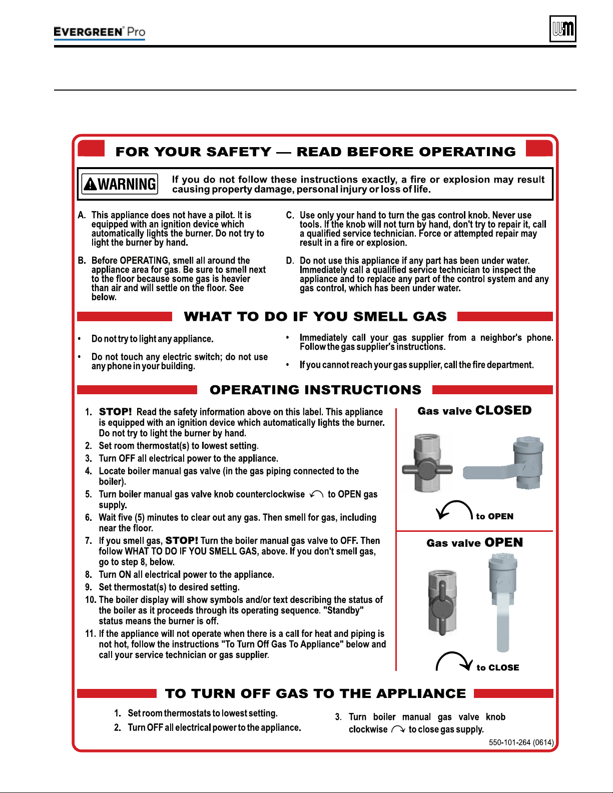
Part number 550-100-211/0122
– 89 –
220 /29 9/3 00 /39 9
Figure87 Operating instructions (WARNING — Verify that the Control is set for the correct boiler model before
proceeding.)
(continued)

Checksystemandboiler
1. Check system piping for leaks. If found, shut down boiler and
repair immediately. (See WARNING on page86 regarding
failure to repair leaks.)
2. Vent any remaining air from system using manual vents. Air
in the system will interfere with circulation and cause heat
distribution problems and noise.
Checkventpipingandairpiping
Check for gas-tight seal at every connection and seam of air pip-
ing and vent piping.
Venting system must be sealed gas-tight to prevent
ue gas spillage and carbon monoxide emissions
which will result in severe personal injury or death.
Checkgaspiping
Check around the boiler and inside the boiler jacket for gas odor
following the procedure of page51 of this manual.
If you discover evidence of any gas leak, shut down
the boiler at once. Find the leak source with bubble
test and repair immediately. Do not start boiler
again until corrected. Failure to comply could re-
sult in severe personal injury, death or substantial
property damage.
Propaneboilers—verifyconversion
Verify boiler has been converted for propane. See page12 .
DO NOT adjust or attempt to measure gas valve outlet
pressure. e gas valve is factory-set for the correct outlet
pressure. is setting is suitable for natural gas and pro-
pane, requiring no eld adjustment.
Attempting to alter or measure the gas valve outlet pressure
could result in damage to the valve, causing potential severe
personal injury, death or substantial property damage.
Evergreen
®
boilers are shipped ready to re natural gas ONLY.
Failure to comply could result in severe personal injury,
death or substantial property damage.
Checkame&combustionwithinstruments
1. Initiate a call for heat on one of the thermostat inputs.
2. Access the Evergreen
®
Control contractor menus by pressing
and holding the UP and DOWN arrow keys for seven seconds.
3. Make sure the Max ring rate is set to the maximum given
in the table. If not, adjust as necessary. en navigate to
DIAGNOSTICS — Manual test mode (see page101 for proper
instructions on testing a multiple boiler system) and force the
ring rate to HIGH (High re).
4. Look at the ame through the ame inspection window.
e high re ame should be blue and should be stable. e
burner surface should be covered with orange dots.
5. Insert combustion analyzer probe — Remove the ue
temperature sensor from the ue pipe and insert a combus-
tion test probe.
6. Test for CO
2
(or O
2
) and for CO. e CO
2
values must comply
with Figure88, page91. If results are acceptable, proceed
to step7. IFNOT, follow the instructions under “Gas Valve
Adjustment” on page91 to set the throttle screw position.
If combustion at either high or low re is
outside the range given in Figure88,page91,
follow the procedure given on page91 for
adjusting the throttle screw on the gas valve. If
throttle screw adjustment does not correct the
problem, then shut down the boiler and con-
tact your local Weil-McLain representative.
rottle screw adjustment must be done only
by a qualied technician, using calibrated test
instruments. Failure to comply could result in
severe personal injury, death or substantial
property damage.
7. Measure natural gas input:
a. Operate boiler 10 minutes. Turn o other appliances.
b. At natural gas meter, measure time (in seconds) required
to use one cubic foot of gas.
c. Calculate gas input:
3600 x 1000
= Btuh
number of seconds from step b
d. Btuh calculated should approximate input rating on boiler
rating label.
8. Use the control display to navigate to Manual test mode (see
Figure81,page81) and force the ring rate to MIN (Low re).
9. Look at the ame through the ame inspection window. e
low re ame should be stable and evenly distributed over
burner surface with a uniform orange color.
10. Repeat the combustion test as instructed in the previous steps.
11. Use the control display to navigate to Manual test mode
(see Figure81,page81)) and force the ring rate to AUTO
(normal operation).
12. Reinstall the ue gas temperature sensor. When replacing the
sensor, remove the rubber grommet from the probe. Insert
the rubber grommet into the ue pipe, then insert the probe
into the rubber grommet.
You must reinstall the ue gas temperature sensor
to prevent ue gas spillage into the boiler enclosure.
Failure to comply could result in severe personal
injury, death or substantial property damage.
Part number 550-100-211/0122
– 90 –
(continued)
220 /29 9/3 00 /39 9
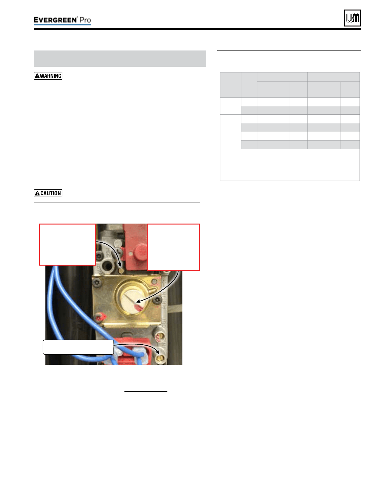
Part number 550-100-211/0122
– 91 –
220 /29 9/3 00 /39 9
DO NOT attempt to adjust the throttle or oset screw
unless done by a qualied technician, and with the use of
calibrated combustion test instruments. Adjust the throttle
or oset screw only as needed to meet the combustion val
-
ues given in Figure89. Must conrm correct low re RPM
b
efore making any adjustments to Oset regulating screw.
1. rottle screw adjustment is onlynecessaryif specied elsewhere
in this manual or if combustion tests indicate the need, as explained un-
der “Check
ame&combustionwithinstruments,” page90.
2. Boiler behavior that might indicate a need to check combustion values
at high re (as per page90) to verify boiler is in adjustment include:
diculty igniting, poor ame stability at low re, combustion noise
or high carbon monoxide values.
3. Combustion readings must be taken at both high re and low re.
DO NOT attempt an adjustment of the throttle screw at low re.
• See Figure88 for location of the throttle screw. Remove the cover
screw to access the throttle adjustment screw.
Adjust the throttle adjustment screw in small movements.
Figure88 Throttle screw (ONLY for use by a qualied technician,
using calibrated combustion test instruments)
Figure89 Acceptable combustion values — measured
values must be within the ranges given
below
Make sure the Max ring rate is set to the maximum and conrm the rpm
valve during operation given in the table Figure96,page100. If not, adjust
as necessary. en navigate to DIAGNOSTICS — Manual test mode
(Figure81,page81) and force the ring rate to HIGH (maximum output).
Aer the boiler has had time to stabilize, take a CO
2
and CO readings.
a. If the CO
2
is HIGH, turn the throttle screw CLOCKWISE to lower
the input. Allow the boiler to stabilize and take another reading.
Continue until the desired CO
2
value is achieved.
b. If the CO
2
is LOW, turn the throttle screw COUNTERCLOCKWISE
to increase the input. Allow the boiler to stabilize and take another
reading. Continue until the desired CO
2
value is achieved.
c. Conrm that the CO is within limits.
Boiler
model
Fuel
High
re Lowre
%
CO
2
CO
ppm
%
CO
2
CO
ppm
220
NG 9.25 ± 0.5 < 100 8.75 ± 0.5 < 50
LP 10.25 ± 0.25 < 120 9.75 ± 0.25 < 50
299/300
NG 9.25 ± 0.5 < 100 8.75 ± 0.5 < 50
LP 10.75 ± 0.5 < 120 10.25 ± 0.5 < 50
399
NG 9.25 ± 0.5 < 100 8.75 ± 0.5 < 50
LP 10.75 ± 0.5 < 120 10.25 ± 0.5 < 50
• Values above are with the boiler front door removed.
Values will increase about 0.2% once the door is reinstalled.
• REINSTALL the boiler door aer completing service.
• e low re CO
2
listed is typical. e valve may vary with conditions,
but must be 0.35% to 0.75% lower than the high re CO
2
value.
1. Adjust the boiler to (LOW) (minimum output) and allow the
boiler to stabilize. Conrm the rpm valve during operation
with the table Figure96,page100.
2. Remove the slotted cap, see Figure88, for Oset screw
adjustment.
a. If the CO
2
is HIGH, turn the offset regulating screw
COUNTERCLOCKWISE to lower the input. Allow the
boiler to stabilize and take another reading. Continue until
the desired CO
2
value is achieved.
b. If the CO
2
is LOW, turn the regulating screw CLOCKWISE
to increase the input. Allow the boiler to stabilize and take
another reading. Continue until the desired CO
2
value is
achieved.
c. Conrm that the CO is within limits.
CO
2
1. Turn o the boiler and then turn it back on and put in Test
Mode at maximum. Ensuring the CO2 setting level has re-
mained unchanged and conrm that CO is within limits.
2. Reduce to minimum and re-check the minimum rate
output ensuring the CO2 setting level has remained un-
changed and confirm that CO is within limits.
3. In the event that the CO2 and CO cannot be ob-
tained, please contact your Weil-McLain representative.
4. Should you require any assistance during the set up procedure
contact your Weil-McLain representative if the problem cannot
be addressed with the information provided in this manual.
Checkignitionsystemsafetyshutoffdevice
1. Aer the boiler has been installed, turn o the boiler.
2. Shut o the manual gas valve located on the gas line to stop
ow of fuel to the boiler.
3. Turn on the boiler. It will start the ignition sequence, but will
not light. Aer some time, the boiler will lockout, the display
screen will turn red, and the Control will ash “Ignition Fault”.
It means that the boiler tried to ignite without success for ve
(5) times and went into Lockout mode. is means that the
ignition system safety device worked properly.
4. Clear the Lockout condition by selecting “Manual Reset” in
the Diagnostic Menu.
5. Open the manual gas valve located on the gas line to resume
fuel supply to the boiler.
(continued)
GasInletPressure
TestPort
OffsetRegulatingscrew
• Turn clockwise
to increase CO
2
.
• Turn counter-clock-
wise to decrease CO
2
.
Note: Must remove cover.
Throttle adjustmentscrew
• Turn counter-clockwise
to increase CO
2
.
• Turn clockwise to
decrease CO
2
.
Part number 550-100-211/0122
– 92 –
1. Follow instructions in this manual to set and verify operation
of the boiler controls.
2. Follow low water cuto manufacturers instructions (If in-
stalled).
Control set for the correct boiler model?
Installation date and installer contact information entered
into Control?
Boiler and heat distribution units lled with water?
Water chemistry veried per page86?
Sentinel X100 corrosion inhibitor added and water tested to
be within range?
Automatic air vents, if used, opened one full turn?
Air purged from system?
Air purged from gas piping? Piping checked for leaks?
Condensate line primed?
Propane venturi installed for propane ring and propane
conversion label axed to jacket?
Evergreen
®
boilers are shipped ready to re natural
gas ONLY. To re on propane, you must follow the
instructions in this manual to install the propane
venturi kit, See page12. Failure to comply could
result in severe personal injury, death or substantial
property damage.
ermostat circuit wiring checked to ensure there are no
stray voltages?
Followed Operating Instructions, Figure87,page89?
Burner ame and combustion veried per pages 90 and91?
Control operation for space heating and DHW (if used) veri-
ed per this manual?
Additional eld-installed controls tested as outlined by control
manufacturers? (Boiler should be operating and should go o
when controls are tested. Verify controls cause automatic reset
lockout or manual reset lockout as desired.)
Additional eld-installed limit control(s) set to system tem-
perature requirements? Balancing valves and controls adjusted
to provide design temperature to system?
Flow adjusted/balanced for each zone of multiple zones
systems?
ermostat heat anticipator (if available) set properly?
Boiler cycled with thermostats (and with DHW aquastat, if
installed) — Raised to highest setting and veried boiler goes
through normal startup cycle? Lowered to lowest setting and
veried boiler goes o?
Natural gas input measured? (page90)
Incoming gas pressure checked by connecting manometer
to gas valve ahead of boiler? (Gas pressure must be at least
the minimum values given on page18, with boiler operating
at high re, and no more than 14 inches (356mm) w.c. with
boiler operating or boiler o.)
Observed several operating cycles for proper operation?
Room thermostats set to desired room temperature (and
DHW aquastat, if installed, to desired DHW storage tem-
perature)?
All instructions shipped with this boiler reviewed with owner
or maintenance person?
Fill in Installationcerticate, page131.
Return instructions to envelope and give to owner or place
inside boiler housing.
Fill out start-up data on the Installation
and Service Certicate, page131.
(continued)
CheckHeatexchangerandventseals
1. Operate the boiler on HIGH re.
2. Using an inspection mirror, move the mirror around all heat
exchanger joints and vent pipe connections at the top of the
boiler and at the connection to the condensate dish.
3. A leak would appear as vapor on the surface of the mirror.
4. If there is any indication of a leak at any joint, immediately
shut down the boiler.
a. If possible, tighten the retaining screws or nuts (without
over-tightening).
b. If this does not correct the problem, disassemble the
components where the leak appeared. Use the procedures
given in Maintenance.
c. When disassembling components, inspect gaskets to see
if there is damage. Replace any damaged gasket.
d. Contact your Weil-McLain representative if the problem
cannot be addressed with the information provided in
this manual.
5. Condensate dish joint
a. If the inspection mirror check shows a leak at the con-
densate dish-to-heat exchanger joint.
or
If the mirror test does not reveal a leak at the condensate
dish joint, but there are signs of weepage or other indica-
tions that there might be leakage, the boiler must not be
operated until a new sealing ring is obtained. Follow the
instructions supplied with the sealing kit to disassemble
boiler components as necessary to access and replace
the seal.
220 /29 9/3 00 /39 9

Part number 550-100-211/0122
– 93 –
220 /29 9/3 00 /39 9
Follow the service and maintenance procedures given throughout this manual and in component literature shipped
with the boiler. Failure to perform the service and maintenance could result in damage to the boiler or system. Failure to
follow the directions in this manual and component literature could result in severe personal injury, death or substantial
property damage.
Figure90 Service and maintenance schedules
Ownermaintenance
(see Evergreen
®
User’s Information Manual)
Daily
y Check boiler area.
y Check air openings.
y Check pressure/temperature
gauge.
y Verify boiler front door is
securely in place.
Monthly
y Check vent piping.
y Check air piping.
y Check relief valve.
y Check condensate drain
system.
y Check automatic air vents
(if used).
y Verify that domestic hot
water is being supplied
to xtures at the correct
temperature.
(If Indirect Tank installed)
Every
6months
y Check boiler piping (gas and
water).
y Operate relief valve.
Servicetechnician
(see page numbers indicated for details)
ANNUALSTART-UP(SeeFirst-yearspecialinspection)
y Handling ceramic ber materials . . . . . . . . . . . . . . . . . 94
y First-year special inspection . . . . . . . . . . . . . . . . . . . 94
y Address reported problems . . . . . . . . . . . . . . . . . . . 95
y Inspect boiler area . . . . . . . . . . . . . . . . . . . . . . . . 95
y Inspect boiler interior & door gaskets . . . . . . . . . . . . . . 95
y Clean condensate trap . . . . . . . . . . . . . . . . . . . . . . 95
y Check all piping for leaks . . . . . . . . . . . . . . . . . . . . 96
y Check air openings. . . . . . . . . . . . . . . . . . . . . . . . 96
y Inspect ue vent system and air piping . . . . . . . . . . . . . 96
y Check water system . . . . . . . . . . . . . . . . . . . . . . . 96
y Remove the burner access panel . . . . . . . . . . . . . . . . 96
y Remove and inspect ignition electrode assembly and wiring . . 97
y Remove and inspect ame sense rod and wiring . . . . . . . . 97
y Remove, inspect and clean the burner. . . . . . . . . . . . . . 97
y Inspect combustion chamber and refractory . . . . . . . . . . . 97
y Replace all components . . . . . . . . . . . . . . . . . . . . . 98
y Check all boiler wiring . . . . . . . . . . . . . . . . . . . . . . 99
y Check control settings . . . . . . . . . . . . . . . . . . . . . . 99
y Inspect pressure switch, wiring and tube . . . . . . . . . . . . 99
y Perform startup and checks . . . . . . . . . . . . . . . . . . . 99
y Check low water cutoff service light . . . . . . . . . . . . . . . 99
y Check burner ame and ame signal . . . . . . . . . . . . . . 99
y Check blower speeds . . . . . . . . . . . . . . . . . . . . . .100
y Check ue gas temperature . . . . . . . . . . . . . . . . . . .100
y Check boiler relief valve . . . . . . . . . . . . . . . . . . . . .101
y Reinstall jacket door after servicing . . . . . . . . . . . . . . .101
y Review with owner . . . . . . . . . . . . . . . . . . . . . . . .101
Part number 550-100-211/0122
– 94 –
HANDLI NG CERAMIC FIBER
MATERI ALS
REMOVINGCOVERPLATEREFRACTORY
e Evergreen
®
cover plate refractory contains
ceramic ber
materials that have been identied as
carcinogenic, or possibly carcinogenic, to humans
.
Ceramic bers can be converted to cristobalite in
very high temperature applications.
e International Agency for Research on Cancer
(IARC) has concluded, “Crystalline silica inhaled in
the form of quartz or cristobalite from occupational
sources is carcinogenic to humans (Group 1).”:
Avoid breathing dust and contact with skin and eyes.
• Use NIOSH certied dust respirator (N95). is type of
respirator is based on the OSHA requirements for cris-
tobalite at the time this document was written. Other
types of respirators may be needed depending on the job
site conditions. Current NIOSH recommendations can
be found on the NIOSH web site at http://www.cdc.gov/
niosh/homepage.html. NIOSH approved respirators,
manufacturers, and phone numbers are also listed on
this web site.
• Wear long-sleeved, loose tting clothing, gloves, and eye
protection.
Handle carefully to minimize dust that could be caused by
abrasion.
If replacement is necessary, remove the refractory from the
boiler and place it in a plastic bag for disposal.
Wash potentially contaminated clothes separately from other
clothing. Rinse clothes washer thoroughly.
NIOSHstatedFirstAid
Eye: Irrigate immediately.
Breathing: Fresh air.
FIRST
-
INSPECT ION
It is recommended that you obtain
a Weil-McLain
Evergreen
®
Boiler
Maintenance kit before attempting
the rst-year inspection, to ensure
all parts that may be needed are
available
. This kit includes essential
components, gaskets and seals required to
perform the annual start-up procedures.
See listing in Replacement parts. ese
parts must be on hand when you perform
the rst-year inspection in the event they
must be replaced.
Failure to replace the items above when
needed could result in severe personal
injury, death or substantial property dam-
age.
1. No later than 12months aer the boiler is in-
stalled, perform a rst-year inspection of the boiler.
is should include the following inadditionto
routineannualstart-upprocedures
.
a. Inspect the heat exchanger and clean if nec-
essary (see page111 for access and cleaning
procedures).
b. Inspect the cover plate refractory and gasket.
Replace if not in good condition.
c. Inspect the burner carefully. Clean the burner
thoroughly using a vacuum cleaner or com-
pressed air if needed.
d. Make sure there is no blockage or accumula-
tion of debris in the burner or the burner ports.
Replace the burner if necessary.
e. Check the burner for tightness.
f. Disconnect the condensate trap and drain lines.
Inspect, then ush thoroughly. Reinstall and
rell the trap per page88.
g. Check heat exchanger seals and vent seals, pro-
cedure described on page92, “Check exchanger
and vent seals”.
2. Determine any follow-up maintenance and service
needs based on the condition of the heat exchanger
and condensate lines.
a. If the heat exchanger shows substantial fouling,
or if condensate lines show accumulation of
sediment, schedule a follow-up service call to
perform the rst-year inspection again, sooner
than the normal twelve months between.
b. Heavy fouling of the exchanger or condensate
lines indicates possible combustion air contami-
nation. Inspect the air intake area carefully, and
remove possible contaminants. See page19, for
products to avoid.
You must eliminate causes of corrosion
and contamination to ensure reliable
operation of the boiler and system.
ANNU AL ST ART UP
Theboilershouldbeinspectedandstarted
annually, at the beginning of the heating season,
only by a qualied service technician. In addition,
the maintenance and care of the boiler designated
in Figure90,page93 and explained on the follow-
ing pages must be performed to assure maximum
boiler eciency and reliability. Failure to service
and maintain the boiler and system could result in
equipment failure.
TOOLS REQUI RED
Before beginning annual start-up or rst-year special inspec-
tion, obtain the tools listed on page102.
220 /29 9/3 00 /39 9
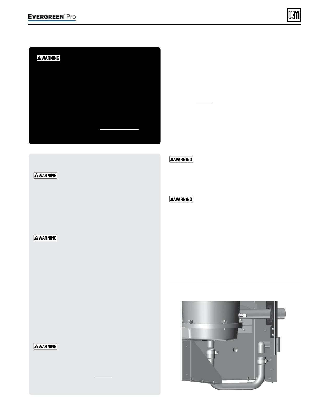
(continued)
Inspect any problems reported by owner and correct before
proceeding.
1. Verify that boiler area is free of any combustible materials,
gasoline and other ammable vapors and liquids.
2. Verify that air intake area is free of any of the contaminants
listed on page19 of this manual. If any of these are present
in the boiler intake air vicinity, they must be removed. If
they cannot be removed, reinstall the air and vent lines per
this manual.
1. Remove jacket front door and inspect interior of boiler.
2. Visually inspect the door gaskets. Make sure all are in good
condition. Obtain replacements if any gasket is damaged.
Door gaskets must be intact, and must provide a
reliable seal. Replace any damaged gasket.
3. Remove the venturi air inlet silencer and clean if necessary.
Reinstall silencer.
4. Vacuum any sediment from the inside of the boiler and
components. Remove any obstructions.
Do not use solvents to clean any of the boiler
components. e components could be damaged,
resulting in unreliable or unsafe operation.
1. See Figure91. Loosen condensate trap line hose clamps and
remove trap line.
2. Empty water from trap line and inspect. Flush out if needed
with fresh water.
3. Check condensate elbow, tee, and condensate line to drain.
Flush if necessary to clean.
4. Fill trap with fresh water.
5. Reinstall condensate trap line and tighten hose clamps.
DO NOT SERV I CE T H E BOI LER
WI THOUT AN Evergre en
®
INSPECTION K I T AVAILABLE
Before each annual inspection, obtain an EVG Inspection
Kit, which includes parts required for the procedures
given in this manual. It is recommended to also obtain
an EVG Maintenance Kit, which includes additional parts
that may be required if inspection of components indicates
the need for replacement. See Replacement parts for kit
part numbers.
ELECTRICALSHOCKHAZARD — Discon-
nect all electrical power to the boiler before
attempting maintenance procedures. Failure
to complete could result in severe personal
injury, death or substantial property damage.
Reinstall boiler jacket door aer start-up or
servicing. e boiler front door must be se-
curely fastened to the boiler to prevent boiler
from drawing air from inside the boiler room.
is is particularly important if the boiler is
located in the same room as other appliances.
Inspect boiler jacket door gaskets. Gaskets
must be in good condition, with no tears or
gaps. Replace if necessary.
Failure to keep the door securely sealed and
fastened could result in severe personal injury
or death.
Removing and reinstalling components can
change boiler behavior. Aer any maintenance
procedure, you must prove the boiler is oper-
ating correctly. To do so, follow the complete
procedure for boiler and system start-up,
beginning on page86. Failure to comply
could result in severe personal injury, death
or substantial property damage.
Part number 550-100-211/0122
– 95 –
220 /29 9/3 00 /39 9
Figure91 Condensate drain line cleaning
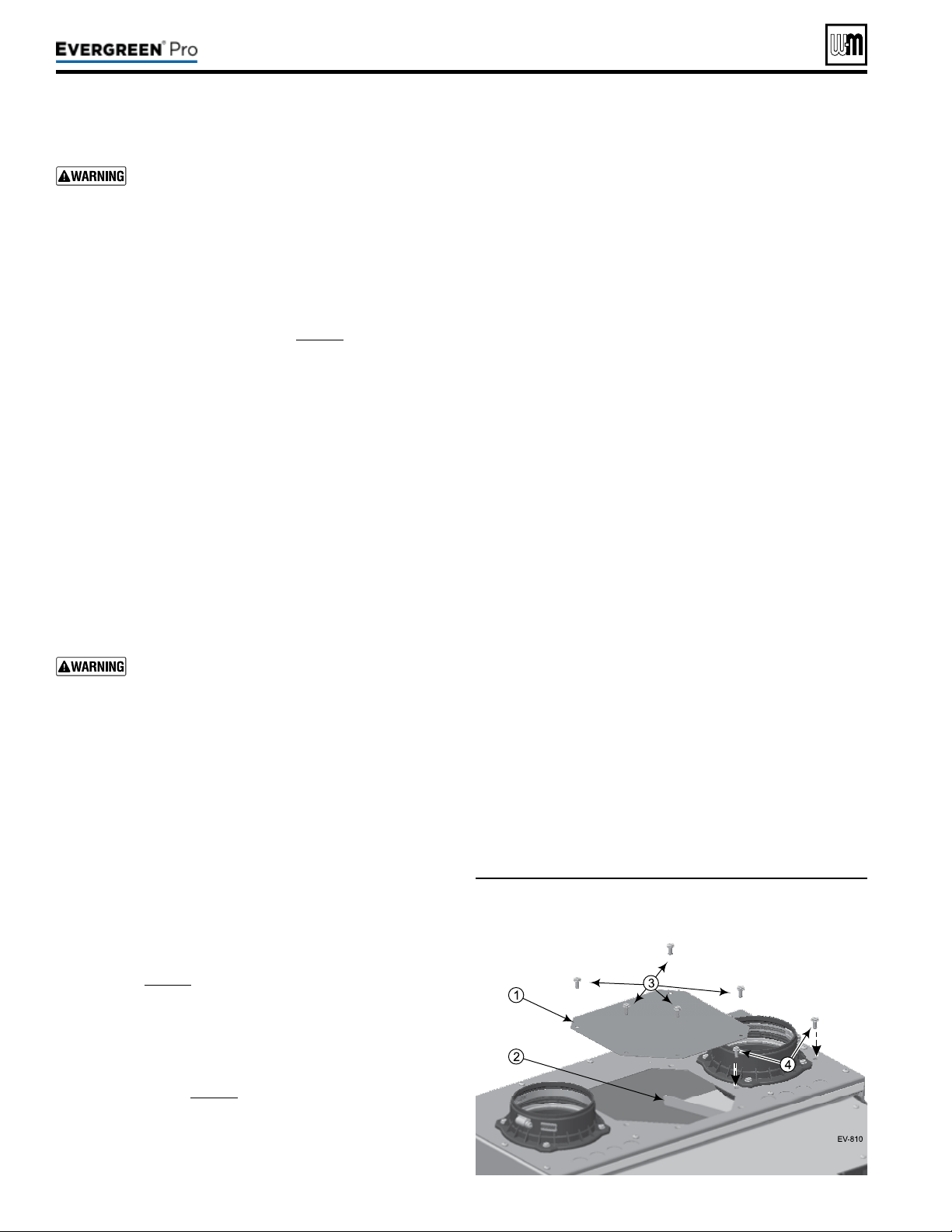
Eliminate all system or boiler leaks. Continual fresh
make-up water will reduce boiler life. Minerals
can build up in the heat exchanger, reducing heat
transfer, overheating heat exchanger, and causing
heat exchanger failure. Leaking water may also
cause severe property damage.
1. Inspect all water and gas piping and verify to be leak free.
2. Look for signs of leaking lines in the system and in the boiler
and correct any problems found.
3. Check gas line using procedure on page51.
1. Verify that combustion and ventilation air openings to the
boiler room and/or building are open and unobstructed.
2. Check operation and wiring of automatic combustion air
dampers, if used.
3. Verify that boiler vent discharge and air intake are clean and
free of obstructions.
Visually inspect entire ue gas venting system and combustion air
piping for blockage, deterioration or leakage. Proper replacement
of damaged components, reassembly, and resealing of the vent-
air intake system must be done if any of these signs are present
in accordance with the vent manufacturer’s instructions. Verify
that air inlet piping is connected and properly sealed.
Failure to inspect for the above conditions and have
them repaired can result in severe personal injury
or death.
1. Verify all system components are correctly installed and
operational.
2. Check the cold ll pressure for the system. Verify it is correct
(usually around 12 PSIG).
3. Watch the system pressure as the boiler heats up (during
testing) to ensure pressure doesn’t rise too high. Excessive
pressure rise indicates expansion tank sizing or performance
problem.
4. Inspect automatic air vents and air separators. Remove air
vent caps and briey press push valve to ush vent. Reinstall
caps. Make sure vents do not leak. Replace any leaking vents.
5. Check system water chemistry (pH, hardness and inhibitor
level). See page86.
1. Expansion tanks provide space for water to move in and
out as the heating system water expands due to temperature
increase or contracts as the water cools.
2. Tank types — see page42.
y Closed-type — welded gas tight and located above boiler.
Tank is partially lled with water, leaving an air cushion
for expansion.
y Make sure a closed-type tank is tted with a tank t-
ting, such as the B & G Tank-Trol or Taco Taco-Trol.
is tting reduces gravity circulation of air-saturated
tank water back to the system and prevents the air
from bubbling up through the water as it returns
from the system.
y Do not use automatic air vents in systems with closed-
type tanks. e air will escape from the system instead
of returning to the tank.
y Eventually, the tank will waterlog and no longer
control pressurization. e boiler relief valve will
weep frequently.
y
Diaphragm-orbladder-type — welded gas tight with a
rubber membrane to separate the tank pressurizing air
and the water. May be located at any point in the system,
but preferably located on the suction side of the system
circulator.
y Systems with this type of expansion tank require at
least one automatic air vent, preferably located on
top of an air eliminator, as shown in examples in this
manual.
3. If relief valve has tended to weep frequently, the expansion
tank may be waterlogged or undersized.
a.
Diaphragm-orbladder-typeexpansiontank — rst,
check tank size to be sure it is large enough for the sys-
tem. If size is too small, add additional tank (or tanks) as
necessary to provide sucient expansion. If tank size is
large enough, remove tank from system and check charge
pressure (usually 12 PSIG for residential applications). If
tank won’t hold pressure, membrane has been damaged.
Replace tank.
b.
Closed-typeexpansiontank — tank is most likely water-
logged. Install a tank tting if not already installed. en
check ll level per tting manufacturer’s instructions. If
ll level is correct, check tank size against manufacturer’s
instructions. Replace with a larger tank if necessary.
1. See Figure92.
2. Remove the burner access panel (item1) located on the top
of the boiler jacket by removing the screws (item3).
Part number 550-100-211/0122
– 96 –
Figure92 Remove the burner access panel and screws
(1 and 3) and air bafe and screws (2 and 4)
from the jacket top as shown below
(continued)
220 /29 9/3 00 /39 9

3. Remove the air bae (item2) and screws (item4) from the
jacket top as shown.
1. See Figure 93, page98 (EVG 220 shown) for component
references below.
2. Disconnect the ground wire and ignition cable connected to
the ignition electrode assembly (item7).
3. Use a 3mm Allen wrench to remove the two (2) screws se-
curing the ignition electrode assembly to the heat exchanger
cover plate (item6).
4. Carefully remove the ignition electrode assembly from the
heat exchanger cover plate.
5. Discard the ignition electrode assembly gasket.
6. Inspect the ignition electrodes and ceramic insulators.
a. Remove any white oxides accumulated on the ignition
electrodes using steel wool.
b. Clean the gasket surfaces on the ignition electrode as-
sembly ange and on the mating surface of the heat
exchanger cover plate.
c. If the ignition electrode ceramic is cracked or damaged, or
if the electrodes cannot be cleaned satisfactorily, replace
the ignition electrode assembly with a new one.
7. Slide the new gasket onto the ignition electrode assembly.
8. Set the ignition electrode assembly with new gasket aside for
later re-insertion.
9. Check ignition cable electrical resistance.
a. A good cable will have resistance between 950 and 1050
ohms.
b. Replace cable if not acceptable.
10. Verify all wiring is in good condition and securely attached.
11. Inspect boiler ground wire from heat exchanger access cover
to ground terminal screw in control tray.
a. Check resistance. It should be 0 ohms.
b. Check ground continuity of wiring using continuity
meter.
c. Replace ground wires if results are not satisfactory.
1. See Figure 93, page98 (EVG 220 shown) for component
references below.
2. Disconnect the ame sense wire connected to the ame sense
rod (item8).
3. Use a 3mm Allen wrench to remove the two screws secur-
ing the ame sense rod assembly to the heat exchanger cover
plate. Carefully remove the ame sense rod.
4. Discard the ame sense rod gasket.
5. Inspect the ame sense rod and ceramic.
a. Remove any white oxides accumulated on the ame
sense rod.
b. Clean the gasket surfaces on the ame sense assembly
ange and on the mating surface of the heat exchanger
cover plate.
c. If the ame sense rod is bent or cannot be cleaned satis-
factorily or if the ceramic is cracked or damaged, replace
the ame sense rod assembly with a new one.
6. Slide the new gasket onto the ame sense rod assembly.
7. Inspect ame sense wire from ame sense connector to the
connector at the control module in boiler control tray.
a. Check resistance. It should be 0 ohms.
b. Replace Wire Harness– Low Voltage if results are not
satisfactory.
1. See Figure93,page98 (EVG220 shown).
2. Use a Phillips stubby screwdriver to remove the four (4) M4
screws (item10) that secure the burner access cover (item4)
to the heat exchanger cover plate (item6).
3. Remove the burner access cover (item4) and the burner
(item11).
Use caution when removing the burner to pull it
directly up and out. DO NOT angle the burner as
you remove it. Angling the burner could cause it to
strike the refractory, damaging the refractory and
causing fragments to fall into the heat exchanger.
Should this happen, a heat exchanger refractory
replacement kit must be installed and the heat ex-
changer must be thoroughly cleaned following the
procedures given in this manual and the refractory
replacement instructions.
4. Remove and discard the burner gasket (item12). is gasket
is graphite and may pull apart or stick to the burner on re-
moval. Use a so brush if necessary to remove residue. DO
NOT allow debris to drop into the heat exchanger. A new
gasket must be installed later when the burner is re-inserted.
5. Inspect the burner access cover seal (item13). Discard and
use a new seal during re-assembly if the seal is damaged in
any way.
6. Inspect the interior of the burner. Brush and vacuum the
interior if needed to remove lint or sediment. Alternative
cleaning methods:
a. Blow air or nitrogen from the inside out.
b. Clean with a water spray from inside the burner.
7. Inspect the burner exterior. It must be in good condition,
with no visible damage.
8. Clean the under side of the burner ange (see item15) with
a so brush to remove any gasket fragments remaining.
9. Set the burner aside for re-insertion later.
1. Look into the burner opening in the heat exchanger cover
plate.
2. Use a trouble light and inspection mirror to inspect the heat
exchanger interior.
a. Make sure that there is no debris inside the heat ex-
changer.
b. Use the inspection mirror to check the condition of the
burner refractory that is adhered to the bottom of the
heat exchanger cover plate. It must be in good condition
with no indication of damage or sagging.
Part number 550-100-211/0122
– 97 –
220 /29 9/3 00 /39 9
(continued)
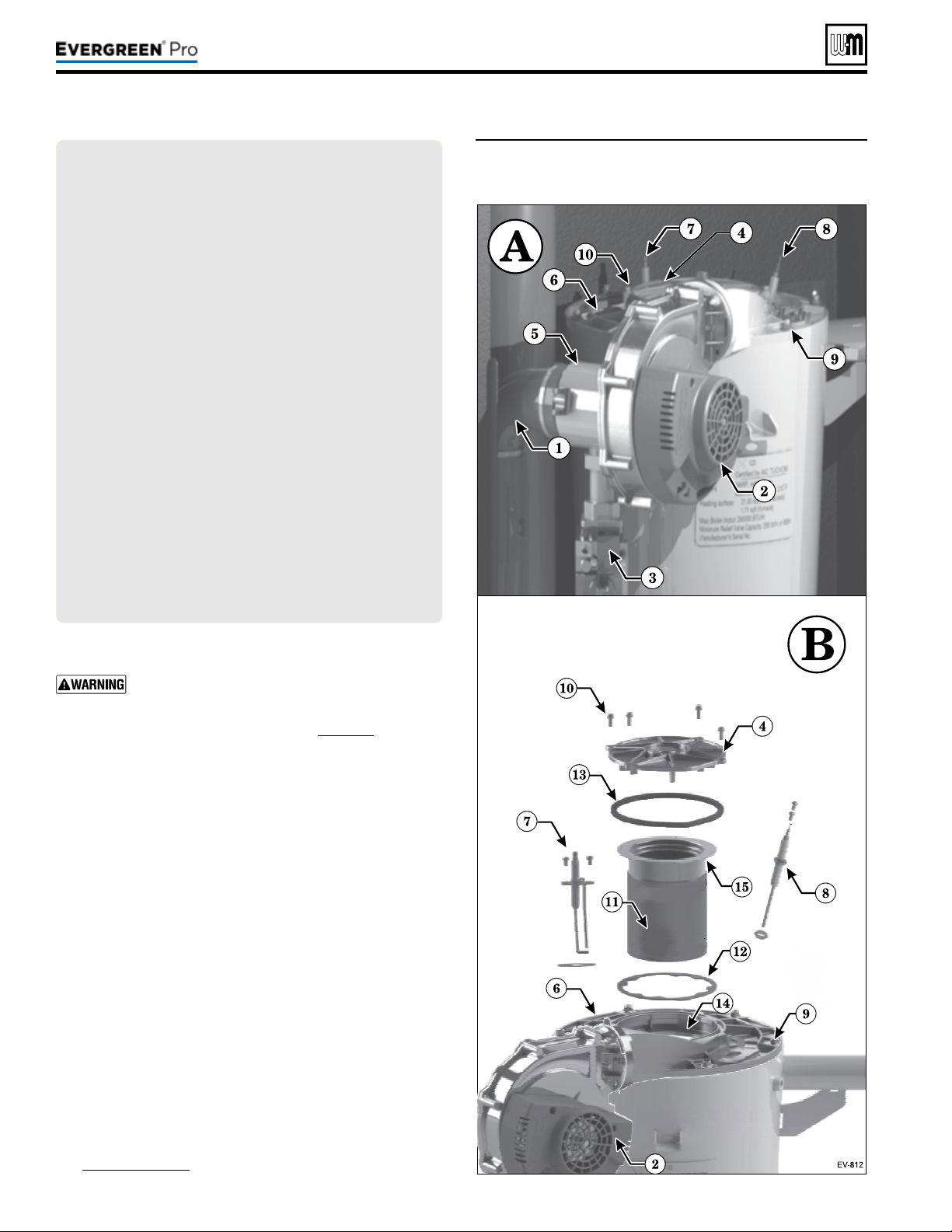
Part number 550-100-211/0122
– 98 –
(continued)
Figure93 Accessing burner, ignition electrode, ame
sense rod and inspection glass assembly
(EVG 220 shown)
LEGEND— Figure93PARTSAandB
A Boiler interior assembled view (Model EVG220 shown;
component locations vary with other models)
B Boiler interior exploded view, showing heat exchanger
cover plate (item6) blower, burner assembly, burner access
cover seal (item13), ignitor, ame sense rod, and sight
glass.
1 Inlet air silencer
2 Blower assembly
3 Gas valve
4 Burner access cover
5 Venturi assembly
6 Heat exchanger cover plate
7 Ignition electrode assembly
8 Flame sense rod
9 Heat exchanger cover plate retainer nuts (6) M6 hex
10 Burner cover retainer screws, M4 Phillips with captive
washers
11 Burner
12 Burner gasket
13 Burner access cover seal
14 Burner gasket sealing surface
15 Burner sealing surface (lower surface of burner ange)
c. Make sure there are no signs of overheating or of ue
gas leakage.
If visual inspection of the heat exchanger indicates
the need, follow the procedures in “Cleaning
the heat exchanger FLUE SIDE or accessing the
burner, when required” on page111 to remove
the heat exchanger cover plate and fully inspect
and clean the interior. Obtain replacement parts
for any components that may be damaged or that
show signs of leakage.
1. Reinstall the burner.
a. Insert a new burner gasket (item12) into the heat exchanger
cover plate (item4).
b. Insert the burner into position.
c. Insert the burner access cover seal into the heat exchanger
cover plate.
d. Place the burner access cover (item4) into position and
secure the four screws (item10).
2. Reinstall ignition electrode assembly and gasket, making
sure that it is correctly positioned. Tighten the two (2) screws
securely.
a. Re-attach igniter cable and ground wire to the ignition
electrode assembly.
3. Reinstall ame sense rod assembly and gasket, making sure that
it is correctly positioned. Tighten the two (2) screws securely.
a. Re-attach the wire to the ame sense rod.
4. Reinstall the burner access panel and air baffle (see
Figure92,page96). Tighten screws securely.
220 /29 9/3 00 /39 9
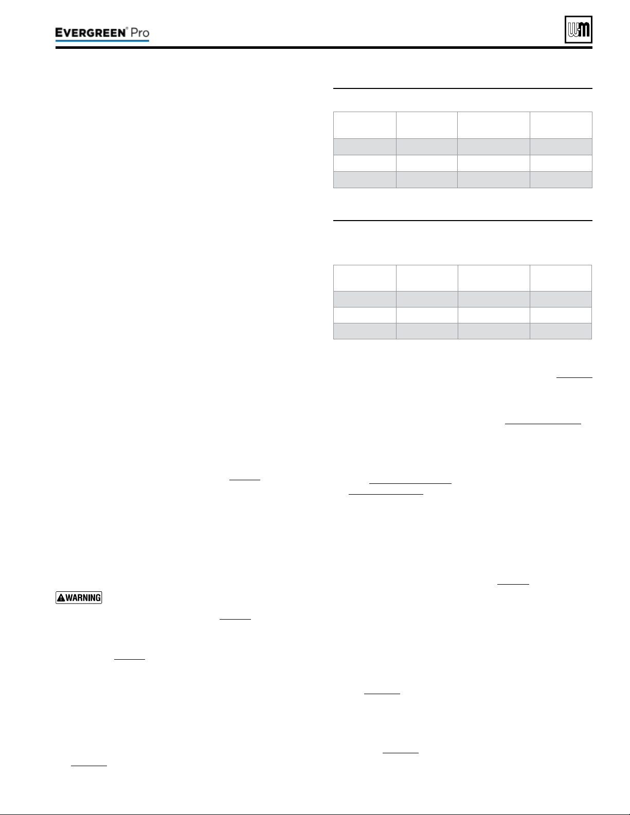
Part number 550-100-211/0122
– 99 –
220 /29 9/3 00 /39 9
Figure94 Minimum ame signal values during operation
Model Minimum
amesignal
Model Minimum
amesignal
EVG 220
100 EVG 220 LP 100
EVG 299/300 100 EVG 299/300 LP 100
EVG 399 124 EVG 399 LP 100
Figure95 Flame signal shut down values — the control
will shut the boiler down if ame signal levels
drop below the values below
Model Shutdown
amesignal
Model Shutdown
amesignal
EVG 220
80 EVG 220 LP 80
EVG 299/300 80 EVG 299/300 LP 80
EVG 399 104 EVG 399 LP 80
(continued)
1. Inspect all boiler wiring, making sure wires are in good condi-
tion and securely attached.
2. Verify that all connectors are securely inserted.
3. Verify ground wires are connected to jacket right side and
control tray cover.
1. Use the Control display to navigate through all settings. Adjust
settings if necessary.
2. Check settings of external limit controls (if any) and adjust
if necessary. Adjust as needed to accommodate the system
design.
1. Inspect pressure switch, ensuring wire connects are properly
connected and tube is secured to pressure port.
2. Inspect tube for any signs of damage or debris collected in
tube, replace if necessary.
3. Aer checking Control Settings (see above), disconnect tube
connection with condensate dish. Gently blow on tube until
pressure switch opens and control displays lockout error.
Clear lockout on control and conrm that lockout does not
re-appear. Reconnect tube connection with condensate dish,
making sure connection is secure.
1. Start boiler and perform checks and tests specied in this
manual.
2. Verify cold ll pressure is correct and that operating pressure
does not go too high. Adjust water pressure and expansion
tank charge pressure as necessary.
3. Complete the check-out procedure on page92.
1. If the low water cuto amber LED is on, the LWCO requires
service.
2. Follow the manufacturer’s instructions packed with the low
water cut-o (shipped as standard equipment with all Ever-
green boilers, in the kit box).
The boiler contains ceramic fiber materi-
als. Use care when handling these ma-
terials per instructions on page94 of this manual.
Failure to comply could result in severe personal injury.
1. Inspect ame through observation window using the pro-
cedure on page90.
2. If ame is unsatisfactory at either high re or low re, check
combustion values. If combustion is properly adjusted, turn
o boiler and allow boiler to cool down. en remove burner
and clean it thoroughly using a vacuum cleaner or compressed
air. Do not use compressed air to clean burner if performed
inside a building.
3. To access the burner, remove the burner access panel and
the cover plate top following the procedure beginning on
page111.
4. If removing the cover plate top and /or the burner, the burner
gasket must be replaced. Follow all instructions on page114
to reinstall all components.
5. Restart the boiler.
6. Inspect the ame at high and low re. If ame is still not
acceptable, check combustion values, Figure89,page91. If
combustion can not be properly adjusted, obtain a replace-
ment burner from Weil-McLain.
7. Check ame signal at both high re and low re.
8. Navigate to Diagnostics/Inputs on the Control display
(see Figure74,page75 for navigation instructions and
Figure80,page80 for the complete Diagnostics menus).
9. e ame signal value must be at least equal to the values
listed in Figure94.
10. If the ame signal drops below this level, the Control will
attempt to correct by increasing the boiler ring rate to in-
crease ame signal.
11. A low ame signal may indicate a fouled ame sense rod.
a. See “Inspect Flame Sense Rod,” page97to remove and
inspect the ame sense rod.
b. If required, clean the ame sense rod as instructed.
c. Check combustion values.
d. If cleaning the ame sense rod does not improve, ame
sense wiring is in good condition, and ground continuity
is satisfactory, replace the ame sense rod.
12. If ame signal still remains low:
a. See “Remove, Inspect and Clean the Burner,” see
page111 to remove and replace burner gasket.
b. Inspect the vent and air piping.
c. en inspect the heat exchanger, following the procedures
given in this manual for removal and reinstallation of the
heat exchanger cover plate and other boiler components
(see page111).
d. Clean the exchanger as described in this manual if nec-
essary.
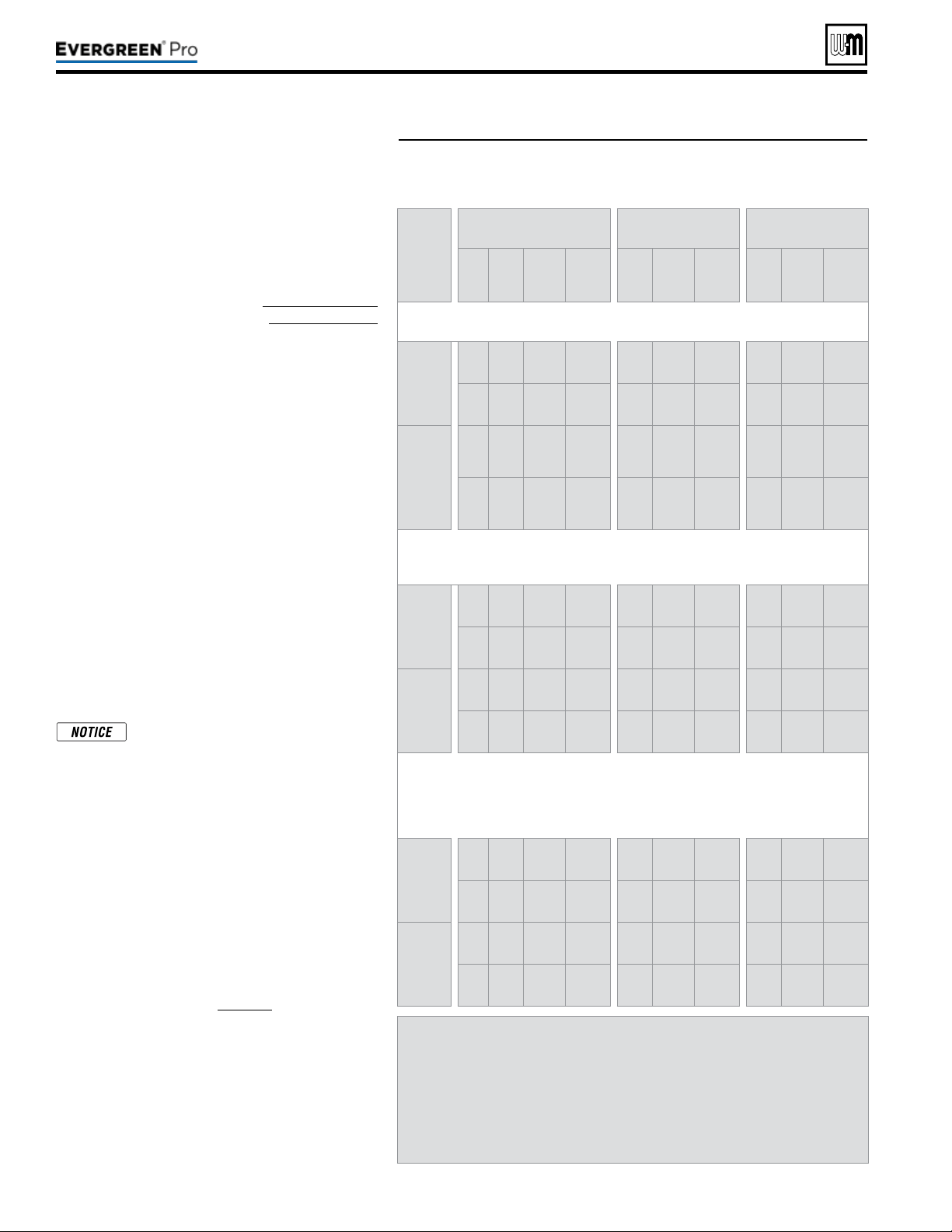
Part number 550-100-211/0122
– 100 –
Figure96 Firing rates and corresponding blower speeds (low re,
ignition, and high re) — for altitudes up to 5,500 feet and
high altitude (above 5,500 feet).
(continued)
1. For installations at altitudes above 2,000 feet,
make sure the control is set up for correct altitude
in the boiler setup menu. e Control automati-
cally adjusts low re and ignition rates to com-
pensate for high altitude conditions.
2. Use the Control display to navigate to DIAGNOS-
TICS/Manual test mode (see Figure74,page75
for navigation instructions and Figure80,page80
for the complete Diagnostics menus).
3. Set the ring rate to MINIMUM (low re).
4. Write down the blower RPM value shown and
compare to the value in Figure96. e value
should no less than the “Minimum setting” and no
higher than the Ignition “Factory setting” listed.
Low re rate (% of Max Rate) is adjusted in the
“Priority” setup menu.
5. Set the ring rate to MEDIUM (ignition rate).
6. Write down the blower RPM value. It should be
within 200 RPM of the value listed in Figure96.
7. Set the ring rate to MAXIMUM (high re).
8. Write down the blower RPM value. It should be
within 200 RPM of the value given in Figure96.
9. If any of the values are outside the ranges listed in
the previous steps, contact the factory for techni-
cal assistance.
Minimum and maximum blower
speeds can be adjusted within limits,
but changing speeds will aect AFUE
ratings.
1. Set the boiler to high re. en adjust the Control
display to view ue gas temperature and boiler
return temperature.
2. e ue gas temperature should be no more than
50°F higher than the boiler return temperature.
3. If the ue temperature is higher than this, shut
down the boiler, allow to cool, and follow the
procedure starting on page111 to clean the heat
exchanger.
Model EVG 220 EVG299/300 EVG 399
Fuel
Type
% RPM Btu/Hr
Note 1
% RPM Btu/Hr
Note 1
% RPM Btu/Hr
Note 1
Factory
setting
NG
10
%
1,115 22,000
10
%
1,175 29,900
10
%
1,210 39,900
LP
10
%
1,250 22,000
10
%
1,145 29,900
10
%
1,150 39,900
High
altitude
NG
11%
to
19
%
1,190
to
1,587
22,000
11
%
to
18
%
1,235
to
1,601
29,900
11
%
to
18
%
1,297
to
1,695
39,900
LP
11
%
to
18
%
1,315
to
1,632
22,000
11
%
to
16
%
1,192
to
1,469
29,900
11
%
to
18
%
1,247
to
1,645
39,900
(“Medium” setting in manual test mode)
Factory
setting
NG
43
%
3,000 94,550 38% 2,800 113,600 39% 3,150 156,300
LP
43
%
2,850 94,550 38% 2,640 113,600 39% 3,000 156,300
High
altitude
NG 57% 3,830
will
vary
51% 3,540
will
vary
52% 4,030
will
vary
LP 57% 3,620
will
vary
50% 3,330
will
vary
52% 3,840
will
vary
(adjust if desired to match maximum system load —
High re % rate = Max heat load / Boiler output)
(adjusting speed will affect boiler AFUE rating)
Factory
setting
NG
96
%
6,030 211,200
96
%
6,100 287,040
96
%
6,930 383,040
LP
96
%
5,660 211,200
96
%
5,800 287,040
96
%
6,600 383,040
Maximum
setting
NG
100
%
6,260 220,000
100
%
6,325 299,000
100
%
7,200 399,000
LP
100
%
5,875 220,000
100
%
6,020 299,000
100
%
6,850 399,000
Note 1 — The boiler will automatically derate the Btu values listed in this
table by 4% per 1,000 feet above sea level.
Low re high altitude rpm’s change starting at 2,500 feet. The rpm’s will
increase from the low value to the high value (11,000 feet) in a linear
fashion.
Ignition high altitude rpm’s change at 5,500 feet.
220 /29 9/3 00 /39 9
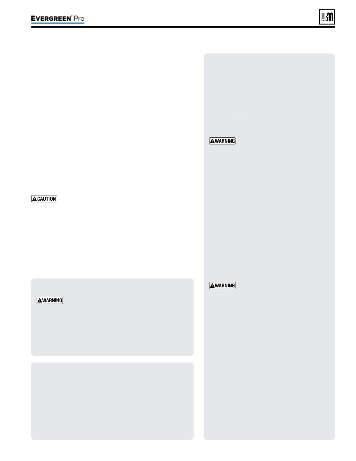
Part number 550-100-211/0122
– 101 –
220 /29 9/3 00 /39 9
(continued)
1. Inspect the relief valve and li the lever to verify
ow as in the following warnings, excerpted from
a relief valve manufacturer’s warning label. Before
operating any relief valve, ensure that it is piped
with its discharge in a safe area to avoid severe
scald potential.
2. Read page41 before proceeding further.
3. Follow instructions below or perform procedures
per relief valve manufacturer’s printed instruc-
tions.
Safety relief valves should be rein-
spected AT LEAST ONCE EVERY
THREE YEARS, by a licensed plumb-
ing contractor or authorized inspection
agency, to ensure that the product has
not been aected by corrosive water
conditions and to ensure that the valve
and discharge line have not been altered
or tampered with illegally. Certain natu-
rally occurring conditions may corrode
the valve or its components over time,
rendering the valve inoperative. Such
conditions are not detectable unless the
valve and its components are physically
removed and inspected. is inspection
must only be conducted by a plumbing
contractor or authorized inspection
agency — not by the owner. Failure
to reinspect the boiler relief valve as
directed could result in unsafe pres-
sure buildup, which can result in severe
personal injury, death or substantial
property damage.
Following installation, the valve lever
must be operated AT LEAST ONCE
A YEAR to ensure that waterways are
clear. Certain naturally occurring min-
eral deposits may adhere to the valve,
rendering it inoperative. When manu-
ally operating the lever, water will dis-
charge and precautions must be taken
to avoid contact with hot water and to
avoid water damage. Before operating
lever, check to see that a discharge line
is connected to this valve directing the
ow of hot water from the valve to a
proper place of disposal. Otherwise
severe personal injury or property dam-
age may result. If no water ows, valve
is inoperative. Shut down boiler until a
new relief valve has been installed.
4. Aer following the above warning directions, if
the relief valve weeps or will not seat properly,
replace the relief valve. Ensure that the reason
for relief valve weeping is the valve and not over-
pressurization of the system due to expansion tank
waterlogging or under-sizing.
1. Review the User’s Information Manual with the owner.
2. Emphasize the need to perform the maintenance schedule
specied in the User’s Information Manual (and in this manual
as well).
3. Remind the owner of the need to call a licensed contractor
should the boiler or system exhibit any unusual behavior.
4. Remind the owner to follow the proper shut down procedure
and to schedule an annual startup at the beginning of the next
heating season.
Reinstall boiler jacket front door aer start-up or servicing. e
boiler front door must be securely fastened to the boiler to pre-
vent boiler from drawing air from inside the boiler room. is is
particularly important if the boiler is located in the same room as
other appliances.
Failure to keep the door securely sealed and fastened could result
in severe personal injury or death.
Single Boiler
1. Navigate to Manual Test Mode screen under DIAGNOSTICS menu.
2. Generate a call for heat and wait until the burner is lit, if not yet in
operation.
3. Press ENTER and select the desired FORCE RATE. Rate will be
forced to setting for 10 minutes.
Multiple Boiler Running
1. Generate a call for heat on a Network Priority or a Local Priority
a. Local Priority—allows Force Rate only on the boiler with the
call for heat. Follow Single Boiler procedure, above.
b. Network Priority—allows Force Rate on any boiler in the net-
work. Follow procedure outline below in steps 2-5.
2. On the Master boiler, navigate to Manual Test Mode screen under
DIAGNOSTICS menu. Select desired boiler to be tested.
3. e Manual Test Mode screen will automatically appear on the boiler
you selected. On the selected boiler’s control, press ENTER and
select the desired FORCE RATE (HIGH, MED, OR LOW).
When forcing a rate on a Network Priority call, only
boilers running Local Priority calls will remain on.
All other boilers on the network will not re until the
Manual Test has ended. Ensure critical applications
remain heated. Long periods of low heating can cause
property damage.
4. e selected boiler will run at the forced rate until it is either re-
turned to AUTO, the user selects “End Manual Test” on the Master’s
Manual Test Mode screen, or aer 30 minutes of inactivity on the
Master control.
5. To test the next boiler, return to the master and select the next
desired boiler to test.
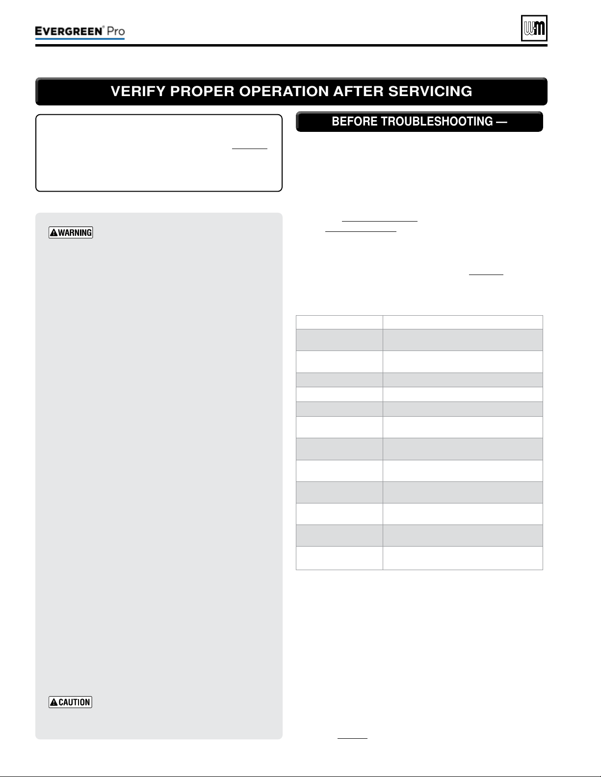
Part number 550-100-211/0122
– 102 –
BEFORE TROUBLESHOOTING —BEFORE TROUBLESHOOTING —
1. See below for tools and kits recommended for troubleshooting
Evergreen
®
boilers.
2. Check for 120 VAC (minimum 102 VAC to maximum 132
VAC) to boiler.
3. Check the Control’s last three lockout histories. (Navigate to
the DIAGNOSTICS menus.)
a. See Figure74,page75 for navigation instructions and
Figure80,page80 for the complete Diagnostics menus.
b. In the DIAGNOSTICS menu, scroll down to PAST ER-
RORS and press the enter key.
c. Record the rst three data records and then highlight the
history record you want to view. See page132, (Data col-
lection sheet).
d. Follow information at the bottom of the screen to navigate
through your lockout histories.
Tool Purpose
#2 Phillips
screwdriver
Multiple uses
Flat blade
screwdriver
To assemble the condensate trap
3 mm Allen wrench
For removing igniter and ame sense screws
10 mm wrench
For removing heat exchanger cover plate
T20 Torx
For removing burner access cover
8 mm socket with 8”
extension
For removing blower
5/16” socket or nut
driver
For removing air bae and burner access panel
Multimeter
Measurements on sensors and electrical com-
ponents
Manometer
(Inclined or digital)
Measure the INLET gas pressure to the boiler
Combustion analyzer
(Digital preferred)
Combustion testing and boiler adjustments
Contact thermometer
Checking surface temperatures of heat exchanger
and pipes
Maintenance kit
ALWAYS have this kit on hand when performing
maintenance in case replacement is required.
1. Make sure thermostat is calling for heat and contacts (includ-
ing appropriate zone controls) are closed. Check for 24 VAC
between thermostat wire nuts and ground.
2. Make sure all external limit controls are either installed (and
closed) or temporarily jumpered for testing.
3. Make sure that connectors to Control are securely plugged in
at module and originating control.
4. Gas pressures:
y Maximum: 14” (356mm) w.c. with no ow (gas valve
lockup pressure).
y Minimum: must be no less than the minimum values given
on page18 while operating on High re.
Failuretoadheretotheseguidelines
canresultinseverepersonalinjury,
deathorsubstantialpropertydamage.
ELECTRI CAL SHOCK H AZARD
e boiler ON/OFF switch does not turn o all power to
the boiler.
TURNOFFALLPOWERTOTHEBOILER
WHENSERVICING
. Internal wiring is still powered when
the switch is o.
DO NOT J UMPER DEV ICES
Never jumper (bypass) any device except for momentary
testing.
REIN STALL JACKET DOOR
e boiler door must be securely fastened to the boiler
to prevent boiler from drawing air from inside the boiler
room. is is particularly important if the boiler is located
in the same room as other appliances. Failure to keep the
door securely fastened could result in severe personal
injury or death.
ALWAYSTURNPOWEROFFTOTHEBOILERTO
PREVENT ELECTRICALSURGES, WHICH CAN
DAMAGEBOILERCOMPONENTS.
LABEL WIRES BEFORE REMOVIN G
Label all wires prior to disconnection when
servicing controls. Wiring errors can cause
improper and dangerous operation.
Before calling for troubleshooting assistance, ll in the
“
Evergreen
®
GasDataCollectionSheet” (page132).
Record the boiler size and CP number (located on the out-
side le jacket above the rating label).
VERIFY PROPER OPERATION AFTER SERVICINGVERIFY PROPER OPERATION AFTER SERVICING
220 /29 9/3 00 /39 9
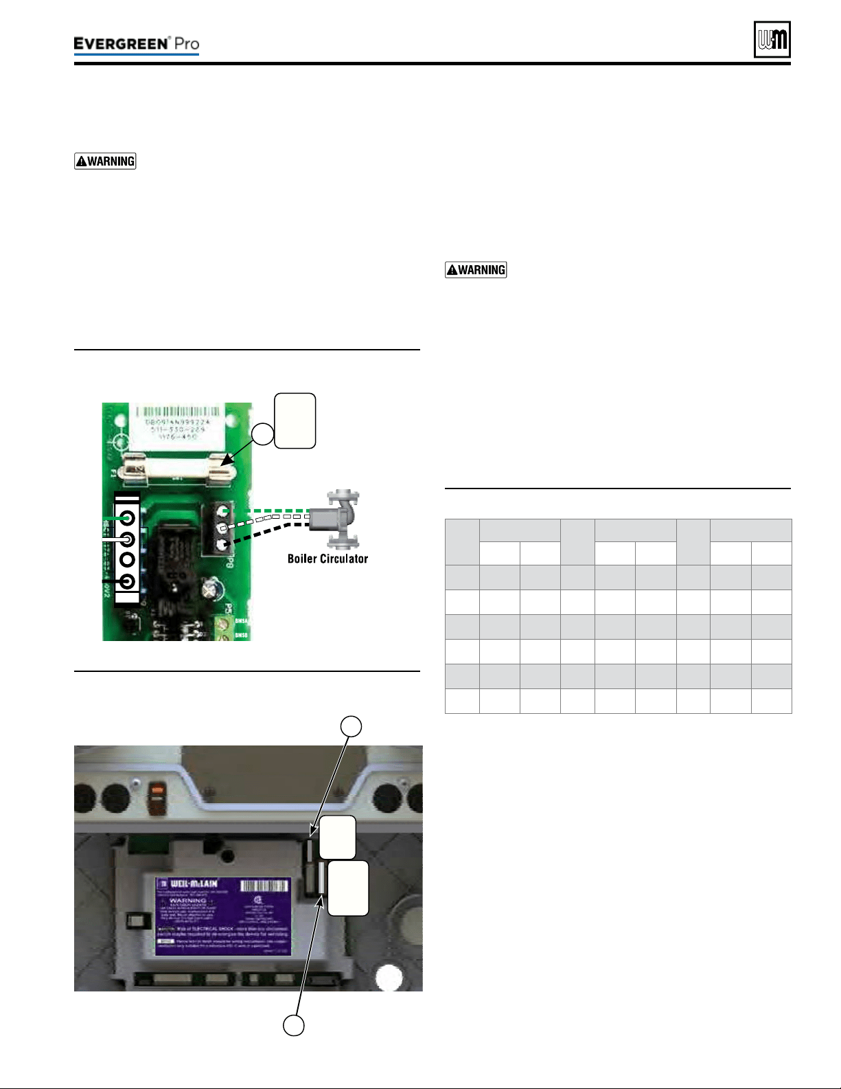
Part number 550-100-211/0122
– 103 –
220 /29 9/3 00 /39 9
(continued)
Temp
(°F)
Sensorohms Temp
(°F)
Sensorohms Temp
(°F)
Sensorohms
Min Max Min Max Min Max
32 34265 37871 90 8504 9399 150 2517 2782
40 27834 30764 100 6847 7568 160 2091 2311
50 21630 23907 110 5545 6129 170 1744 1928
60 16944 18727 120 4517 4992 180 1461 1615
70 13372 14780 130 3698 4088 190 1229 1359
80 10629 11747 140 3043 3364 200 1038 1147
Figure97 Boiler Circ fuse (control cover removed)
Figure98 Control module fuses (control cover removed)
Figure99 Sensor resistance valves
5. If necessary, replace one or all of the fuses:
a. Item 1 - Boiler Circ fuse is a 3-amp fast-blow (Littelfuse
0314003 MXP or Bussman ABC-3-R).
b. Item 2 - Low voltage circuit fuse is a 3-amp fast-blow
(Littelfuse 0287003).
c. Item 3 - Line voltage circuit fuse is a 12-amp fast-blow
(Littelfuse 0314012 MXP or Bussman ABC-12-R).
Do not jumper either fuse or replace with any fuse
except as specied. Failure to comply could result in
severe personal injury, death or substantial property
damage.
6. Reinstall control tray cover.
1. e boiler temperature sensors (ue, outdoor, return wa-
ter, supply water and system temperature sensors) are all
resistance-type devices. Figure99 shows the correct value
for the sensor at various temperatures. For dual sensors,
the temperature dierence between the sensors must be no
more than 10°F.
2. Use the resistance values at 32°F, 60°F, 70°F and 212°F to
measure the sensor resistance at known temperatures (ice
point, room temperature and sea level boiling point). For
ice point and boiling point, insert the sensor in water at that
temperature. Use an ohmmeter to read resistance value.
3. To check whether the Control is correctly sensing tem-
perature, you can use a resistance decade box. Connect the
decade box temporarily in place of a sensor and read the
corresponding temperature on the Control display. The
temperature should be close to the value corresponding to
the input resistance.
ALWAYS check control fuses before replacing
control or any major components (blower, etc.). If
one of these fuses is blown, it can prevent control
or other components from operating.
1. Turn OFF power to boiler at external line switch. en remove
the jacket door.
2. Remove four (4) screws holding control tray cover in place.
3. Remove control tray cover to access the fuses.
4. Remove and inspect the one (1) fuse (item 1, Figure97)
and remove and inspect the two (2) fuses (items2 and3,
Figure98) on the control module.
Fuse
3-amp
120vac
BoilerCircfuse
1
LineVoltage
LowVoltage
2
3
Fuse
3-amp
24VAC
Fuse
12-amp
120vac
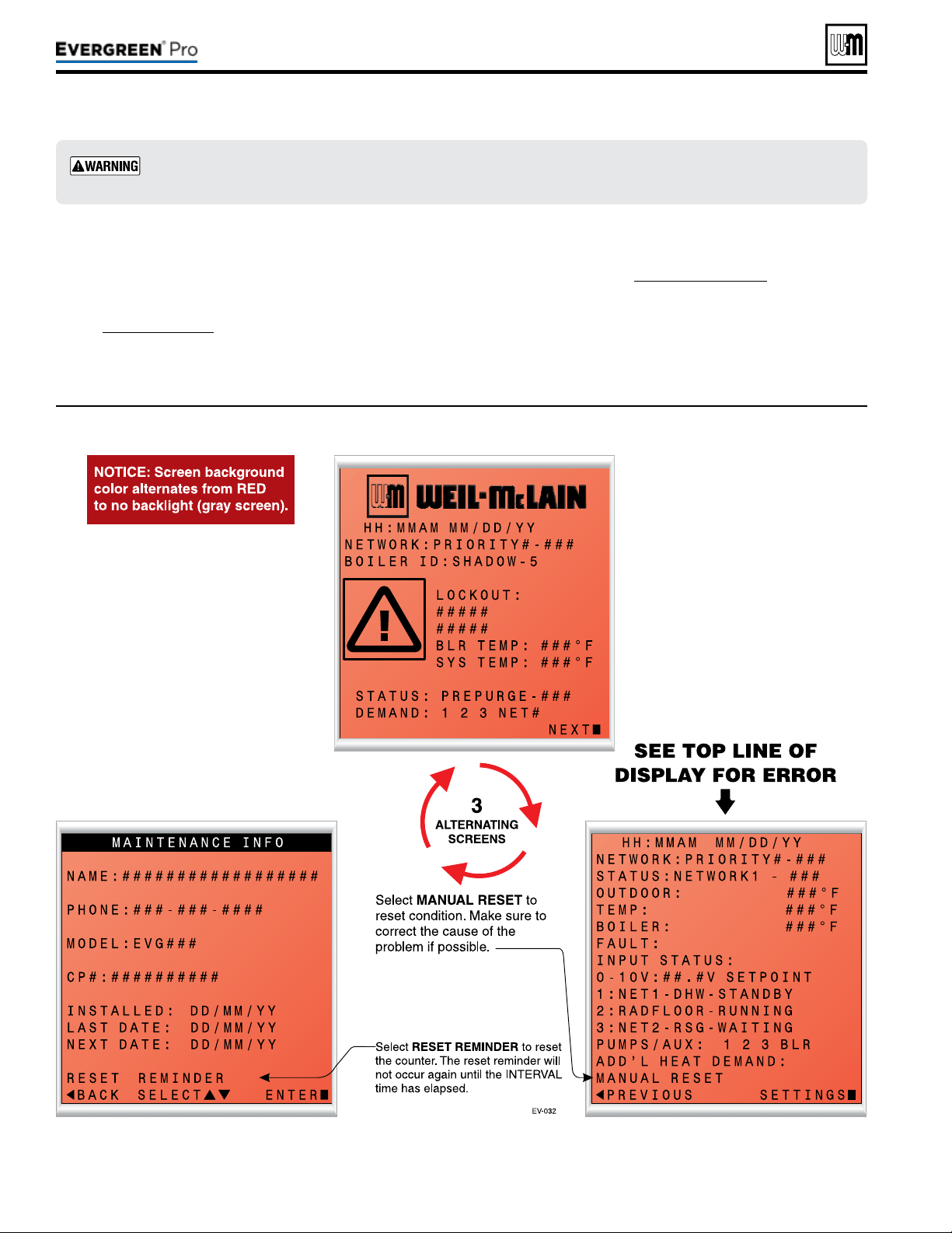
Figure100 Control display toggles when in lockout, with screen ashing red to gray
Part number 550-100-211/0122
– 104 –
(continued)
1. e control provides diagnostic infor-
mation for both automatic reset con-
ditions and manual reset conditions.
See Figure71,page67 for information
available on the control display and
navigation instructions for all menus.
2. Figure100 shows the screen behavior
during a fault condition. e display il-
lustration and text below in Figure100
shows how to reset faults from the
Home Owners screen.
3. Figure101, page105 lists conditions
that will cause the control to display
a constant red screen. e boiler will
automatically restart if the condition
self-corrects or the technician uses the
control’s manual reset screens to reset.
Makesuretodeterminethecausesofoutages.Donotleavetheboileroperatingwithoutacom-
pletediagnosis.
220 /29 9/3 00 /39 9

Figure101 Troubleshooting suggestions for Evergreen
®
boilers — ControlErrorConditionLog
Part number 550-100-211/0122
– 105 –
220 /29 9/3 00 /39 9
(continued)
e Control is able to record information about the boiler’s condition at the time of the three previous faults or errors. is infor-
mation is available to view in Contractor Menus under “DIAGNOSTICS” by selecting “PAST ERRORS.” e control will display
the following information:
Information Description Action
Control Fault
Records the number of internal control faults. Press the < + > key to reset this count.
Ignition Retries
Displays cumulative ignition attempts.
It is recommended that his be reset during yearly
maintenance.
Press the < + > key to reset the count or select this
parameter and press enter to reset.
Manual Reset Count
Records number of lockouts that required a manual
reset since this count was last cleared.
Press the < + > key to reset this count.
Auto Reset Count
Records number of lockouts that have automatically
reset since this count was last cleared.
Press the < + >- key to reset this count.
Lockout History 1
Details of present or last recorded lockout. Select and press the enter key for more details.
Lockout History 2
Details of boiler during the second oldest lockout still in
memory.
Select and press the enter key for more details.
Lockout History 3
Details of boiler during the oldest lockout still in
memory.
Select and press the enter key for more details.
How to read the last 3 lockout histories:
1. Scroll down to “DIAGNOSTICS” and press
the enter key (Square Key in center).
2. Scroll down to “PAST ERRORS” and press
the enter key (Square Key in center).
3. Scroll down to “LOCKOUT HISTORY #”
and press the enter key(Square Key in
center).
4. Review fault information displayed on
screen.
5. Scroll up or down to highlight other choices
and press the enter key to view the details
of the boiler’s condition when the lockout
was recorded.
How to clear all lockout histories:
1. While on the “PAST ERRORS” screen,
hold the Left and Right arrow buttons
simultaneously for 7 seconds.
1. Selecting this will prompt the user to hold the enter button
for a specied length of time. Upon completion, this will
reset the control settings back to factory installed settings.
ONCE THIS IS CHOSEN, PREVIOUS SETTINGS CAN-
NOT BE RECOVERED. ENSURE THIS ACTION IS
TRULY DESIRED BEFORE CONTINUING.
2. Reset to Factory Default can be found on the BOILER
SETTINGS menu, see Figure75,page76.
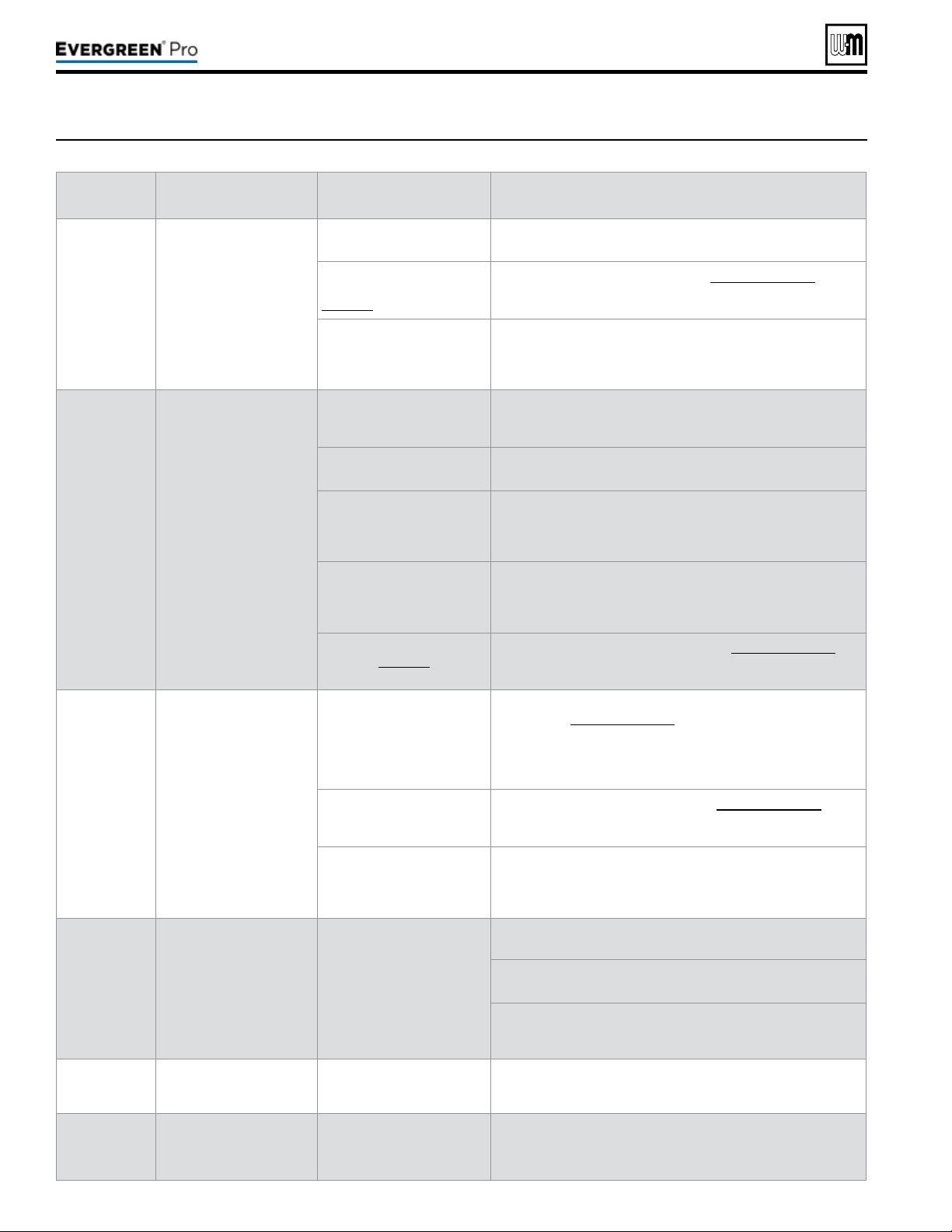
Part number 550-100-211/0122
– 106 –
(continued)
Figure102 Troubleshooting suggestions for Evergreen
®
boilers — Faultdisplays,diagnosticsandcorrectiveactions
Display
Condition Diagnostics Corrective Action(s)
Nothingshown
ondisplay
screenand
boilerwillnot
respondtocall
forheat
Control is not receiving 24V
power.
Check wiring for short circuit
or incorrect wiring.
Correct wiring per wiring diagram including connection of
transformer to the control.
Check 3-amp low voltage
fuse on control shown on
page 103.
Replace fuse with proper part found in Replacement parts. If fuse
blows again recheck wiring per diagram.
Check transformer
connection to the control per
wiring diagram. Check for
24V output of transformer.
Replace transformer if it is receiving 120VAC, but not outputting
24VAC.
Nothing
isshown
indisplay
screenandno
otherboiler
components
areoperating
Control is not receiving
120V power.
Check service switch and/
or circuit breaker to boiler is
turned on.
Turn on service switch to power boiler.
Is there 120 VAC at the
service switch?
Troubleshoot and correct the power supply to the service switch.
Is the
Evergreen's ON/OFF
POWER SWITCH located
on the upper right side of the
boiler, switched ON ?
Turn the Evergreen's power switch to ON.
Check for 120 VAC at the line
voltage terminal block located
inside the top left electrical
compartment.
Correct wiring inside the control pod using the wiring diagram in
this manual.
Inspect 12-amp fuse as
shown on page 103. Replace
if necessary.
Replace the fuse with proper part found in Replacement parts. If
fuse blows again recheck wiring per diagram.
Nothingis
shownon
displayscreen,
butboileris
operating
Occurs if the
communication is lost from
the control to the display.
or
Display contrast needs to
be adjusted.
Check for loose connections
and proper pin alignment/
engagement on the control's
plug P9, Pump/Com board
P6 + J1, and the back of the
display circuit board.
Check for continuity on the wire harness from the display to the
control. See Replacement parts for proper part.
Cycle power off and on using
boiler power switch and
check for operation.
Replace with new display module. See Replacement parts for
proper part.
Look at the screen from other
angles.
Power cycle the boiler, wait about 45 seconds then Press and
hold the Enter button. While holding the Enter button, tap the up
or down buttons to adjust the contrast level. If this does not work
replace display.
TEMP RISE TOO
QUICKLY
Occurs if supply water
temperature in heat
exchanger rises faster than
2º F per second during the
rst two minutes the burner
is on.
Automatically resets after 1
minute delay or using manual
reset on display.
Manual reset is necessary
after 5 automatic resets have
occurred during the same
Priority heat demand. Reset
using manual reset screen on
display.
Verify water pipe is installed correctly per instructions in this
manual.
Verify proper circulator and speed for boiler size and system
requirements.
See message displayed TEMPERATURE SENSOR and follow
procedure for loose connections.
DISPLAY COMM
Fault
Occurs if display
communications out for 30
seconds.
Automatically resets when
communication is re-
established.
Check for a loose connection at the molex plug on the control and
connection on the back of the display.
Hardware Fault
Occurs when micro-
controllers on main board
have a RAM or ROM error,
or communication is cut off.
Check for hardware
damages.
RAM or ROM errors can be reset with the manual reset option.
If problems persist, replace main board.
220 /29 9/3 00 /39 9
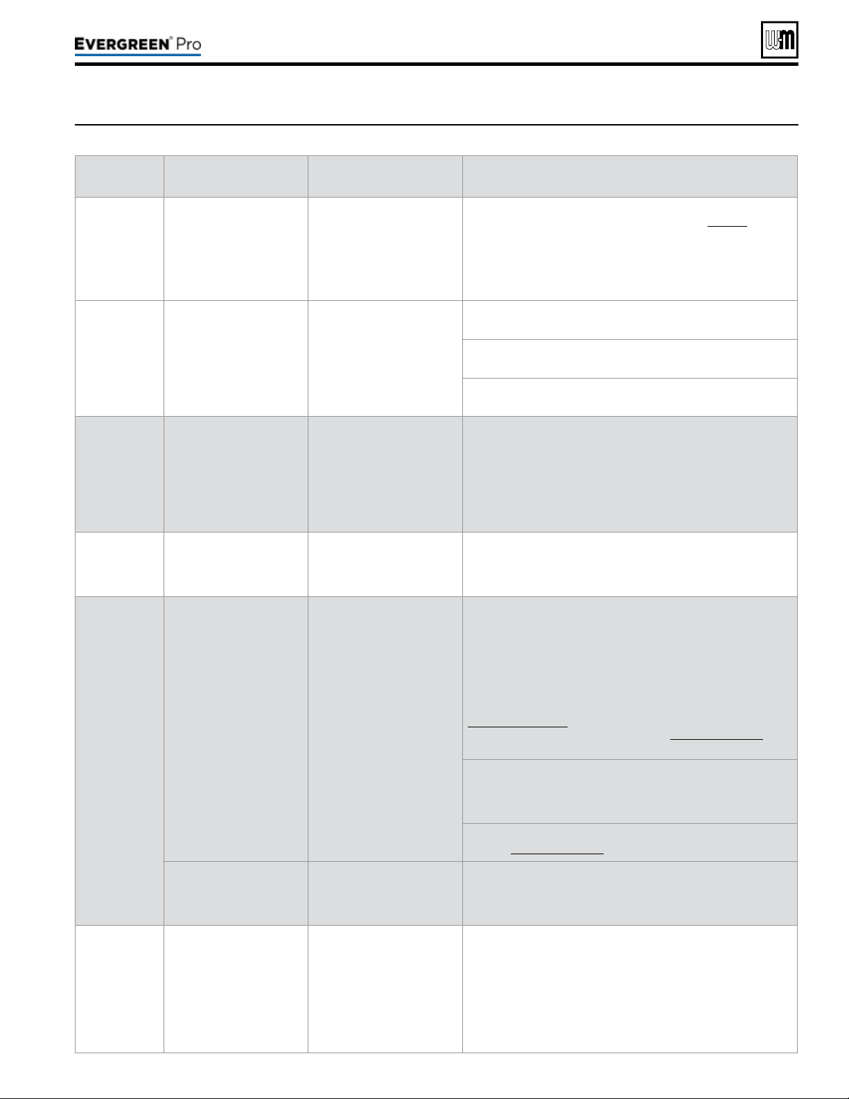
Part number 550-100-211/0122
– 107 –
220 /29 9/3 00 /39 9
Figure103 Troubleshooting suggestions for Evergreen
®
boilers — Faultdisplays,diagnosticsandcorrectiveactions
(continued)
Display
Condition Diagnostics Corrective Action(s)
LOW WTR
CUTOFF OPEN
Occurs if internal low water
cutoff contacts open.
Automatic reset occurs if
contacts are open at least
one second, but less than
5 seconds.
Manual reset of control if
contacts are open longer
than 5 seconds.
Check for low water condition in system. Repair system as
necessary; refer to the piping section starting on page 39.
If low water condition does not exist, check Diagnostics — Inputs
screen to view status of Low Water Cutoff. If shown as OPEN
check wiring between LWCO and control. If wiring is ne, remove
LWCO and Clean probe. If problem still exist, then replace the
LWCO.
SUPPLY 58° F >
RETURN
Boiler Out temperature
has exceeded the Boiler In
temperature by more than
58º F.
Automatically resets after
30 second delay when
conditions no longer exist
or using manual reset on
display.
Verify water pipe is installed correctly per instructions in this
manual.
Verify proper circulator and speed for boiler size and system
requirements.
See message displayed TEMPERATURE SENSOR and follow
procedure for loose connections.
RETURN >
SUPPLY
Occurs if a return water
temperature is greater
than the corresponding
supply temperature by 10º
F or more.
Automatically resets when
condition no longer exists.
Verify proper ow direction of the boiler circulator.
Verify proper placement of system sensors for single or multiple
boiler system. System sensors should be on system piping not on
the boiler loop.
Verify sensors are wired to correct terminal locations.
System sensors may need to be located further away from the
boiler loop connection to the system, if proximity to the boiler loop
is causing sensors to be heated inaccurately.
SUPPLY WATER
TEMPERATURE
TOO HIGH
Occurs when the System
Supply temperature goes
above 200º F when the
burner is running.
Automatically resets when
Supply temperature goes
below 200º F.
Verify proper ow direction of the boiler circulator. This circulator
must be installed to push water through the system.
TEMPERATURE
SENSOR FAULT
Occurs if a temperature
sensor has electrically
shorted (SHORT) or has
become disconnected
(OPEN).
Will automatically reset if the
condition clears.
Check all the temperature readings of the boiler on the
DIAGNOSTICS - TEMPERATURES menu to determine if any
sensors are currently displayed as SHORT or OPEN. Compare
this to the boiler temperatures recorded in the DIAGNOSTICS -
ERRORS - LOCKOUT HISTORY # - TEMPERATURES during
the last several lockout conditions.
Determine which sensors are suspect and measure their
resistance value and compare it to the values shown in
Figure 99, page 103. If the resistance values are incorrect
replace the temperature sensor. Refer to Replacement parts for
proper part number.
Check wire harness for loose connections and pin engagement
at sensor connection, chassis mount connection through control
housing, and the control. Unplug connection at sensor and at
control and check continuity between ends.
If problem persists after checking items above, replace control.
Refer to Replacement parts for kit number.
Occurs if dual temperature
sensors values have
spread by more that 10º F
if the burner is on.
Automatically resets when
sensors are within 10º F.
Follow procedure for above for SHORT and OPEN sensor
conditions to properly diagnose sensor. If measured resistance
values of sensors convert to temperatures separated by more
than 10º F replace the sensor.
FLUE TEMP
TOO HIGH
Occurs if ue temperature
sensor exceeds 210º F
(Warning) or 220º F
(Lockout).
Automatic reset occurs if
temperature drops below
210º F for 2½ minutes.
Manual reset is required if
the temperature rises above
220° F. Reset using manual
reset screen on display.
Follow procedure for above for SHORT and OPEN sensor
conditions to properly diagnose sensor. In addition inspect heat
exchanger combustion chamber and ueways for abnormal wear
or buildup.
Inspect vent system for abnormal wear or damage.
Contact Weil-McLain Technical Support.
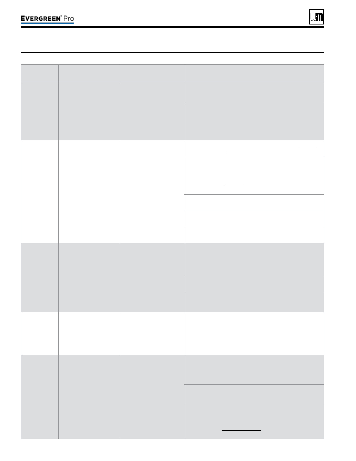
Part number 550-100-211/0122
– 108 –
Figure104 Troubleshooting suggestions for Evergreen
®
boilers — Faultdisplays,diagnosticsandcorrectiveactions
(continued)
Display
Condition Diagnostics Corrective Action(s)
LIMIT OPEN
Occurs if manual or
automatic reset limit op
ens.
Automatic external limit
will reset 2½ minutes after
external limit device closes.
Manual limit fault must be
reset by choosing Manual
Reset on the display.
Is there an external safety device connected? If yes, trouble
shoot the external limit to determine and correct the cause that
opened the limit. Also check for loose wiring connections.
Remove the top right Control tray cover and inspect the
connector.
Ensure a jumper is installed across the MAN LIMIT terminals if
not using a manual reset external limit.
Ensure a jumper is installed across the AUTO LIMIT terminals if
not using a automatic reset external limit.
HIGH TEMP
LIMIT
Boiler temperature sensor
reached High Temp Limit
setting (no higher than 200°
F).
Reset using manual reset
screen on display.
Verify that high limit setting is at least 10° F above the maximum
target temperature plus the off differential.
Verify all isolation valves are open and circulators are
programmed into the control properly.
The boiler circulator output and System Pump/Aux. output can be
congured to turn on or off with each priority. Refer to the control
section starting on page 63 to congure these properly for the
system.
Verify water pipe is installed correctly per instructions in this
manual.
Verify proper circulator sizing for boiler size and system
requirements.
See message displayed TEMPERATURE SENSOR and follow
procedure for loose connections.
FLAME FAULT
Occurs if ame is detected
when there should be no
ame.
Reset using manual reset
screen on display.
Burner may be operating too hot due to incorrect combustion.
Inspect ame and conduct combustion test.
Force boiler into high re. Check ue gases with combustion
analyzer and correct using the maintenance and startup
procedure in this manual.
Verify FLAME SIGNAL value quickly goes to zero on the
DIAGNOSTICS - INPUTS screen when the gas valve closes.
Check for ame at burner via ame current with burner off. Turn
boiler off and watch ame through observation port. If ame
continues after shut down replace gas valve.
GAS VALVE
F A U LT
The control has detected
a problem with gas valve
output circuit.
Control will do automatic
retry; lockout if retry
unsuccessful; retry 1 hour
after lockout — restart if
condition cleared, but lockout
requires manual reset if
condition still present.
If lockout reoccurs replace control.
BLOWER FAULT
Blower unable to reach
required speed or does
not reach 0 RPM when
turned off.
Reset using manual reset
screen on display; Control
will check again after 1 hour
and will automatically restart
if condition is corrected.
Check wire harness for loose connections and pin engagement
at blower connections, chassis mount connection through control
housing, and control. Unplug connection at blower and at control
and check continuity between ends. Blower is connected to both
low voltage and line voltage harness.
Check Diagnostics - Inputs screen with boiler in standby mode
and blower not running. If BLOWER SPEED is not 0 RPM then
replace blower.
If blower does not rotate during ignition sequence check for 120V
power at blower connection. If 120 VAC power at blower motor
and it doesn't start replace blower. Check power at control. If
120VAC is not present at control when boiler is powered replace
Control. Refer to Replacement parts.
220 /29 9/3 00 /39 9
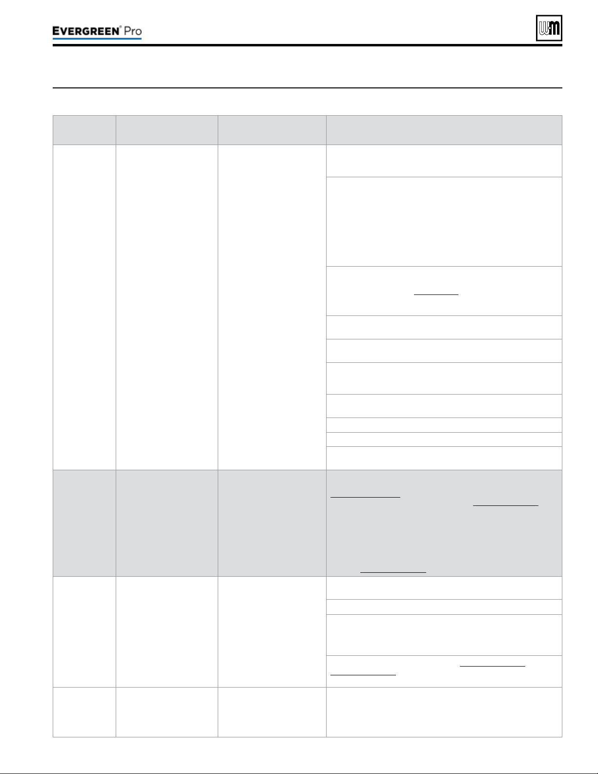
Part number 550-100-211/0122
– 109 –
220 /29 9/3 00 /39 9
Figure105 Troubleshooting suggestions for Evergreen
®
boilers — Faultdisplays,diagnosticsandcorrectiveactions
(continued)
Display
Condition Diagnostics Corrective Action(s)
IGNITION
FAU LT
Boiler went through 5
ignition attempts and never
detected ame or ame
sense value never reached
minimum threshold for
boiler model.
Automatically resets after
1 hour or can be reset by
performing manual reset on
boiler.
Check condensate trap for blockage allowing condensate to
accumulate inside heat exchanger.
Check ignition cable connection.
Fouled, worn, bent, or faulty igniter.
Fouled igniters can be cleaned for additional use with steel wool.
Worn or badly fouled igniters should be replaced with the proper
repair part.
Igniter rods should be parallel with a 3.5 mm (0.138 in) spark gap.
NOTICE: Thin white deposits on the igniter are typical, but brown
or black deposits could be the result of ue gas recirculation.
Thoroughly inspect the venting system and termination for the
possibility of leakage or ue gas feedback into the air line.
Dirty burner and/or heat exchanger will cause high back pressure
and poor ignition.
Follow procedure in the Maintenance section of this manual to
clean burner and heat exchanger. Visual inspection of ueways
may not be sufcient to diagnose condition.
Check combustion settings on high and low re and adjust per
setup instructions if necessary.
Check incoming gas pressure with boiler off and at high re.
Adjust within limits on rating label.
Verify correct boiler model and altitude is selected in control and
correct elevation must be entered when operating above 2,00
feet.
Check ignition cable resistance. Should measure 1000 Ohms
(+/- 50 Ohms).
Check for ue pipe and intake pipe restrictions or blockage.
Check burner fasteners and gaskets.
Check venturi gaskets and proper venturi. (Propane models use
different venturi’s).
OUTDOOR
SENSOR ERROR
Outdoor temperature
sensor short or OPEN.
Will automatically reset if the
condition clears.
Warning only. Supply Max is
targeted until ODT is
restored, if used for target
adjustment.
Determine which sensors are suspect and measure their
resistance value and compare it to the values shown in
Figure 99, page 103. If the resistance values are incorrect
replace the temperature sensor. Refer to Replacement parts for
proper part number.
Check wire harness for loose connections and pin engagement
at sensor connection, chassis mount connection through control
housing, and the control. Unplug connection at sensor and at
control and check continuity between ends.
If problem persists after checking items above, replace control.
Refer to Replacement parts for kit number.
AIR PRESSURE
Switch Open
Occurs when Air Pressure
connection is open.
Reset using Manual Reset
screen on display.
High pressure in the exhaust
pipe or high vacuum in the
boiler intake or cabinet has
caused the air switch to
open. The switch is closed in
normal operating conditions.
Check boiler size selected in control against boiler rating label.
Correct if necessary to select the proper boiler size.
Check exhaust and intake pipe for restrictions or blockage.
Check condensate drain for blockage. If condensate is unable
to drain out of the boiler it can begin to block the ow of exhaust
gases. Clean the condensate collection area of the base and
condensate trap. Rell trap with fresh water.
Check the P7 connection as seen on Figure 65, page 59 &
Figure 66, page 60. Check the connections on the pressure
switch.
Closure Switch
fault
Proof of Closure
connections on P7 Pins 2
and 3 are open.
Soft lockout for 3½
minutes boiler retries. Each
consecutive failure adds 1
minute to lockout time, up to
6½ minutes maximum.
None - Check jumper on correct pins and secure connection.
Flow switch attached - Check correct pump is on, check wiring to
ow switch, and check switch is closing CAD - Check voltage to
damper. Check damper is opening.
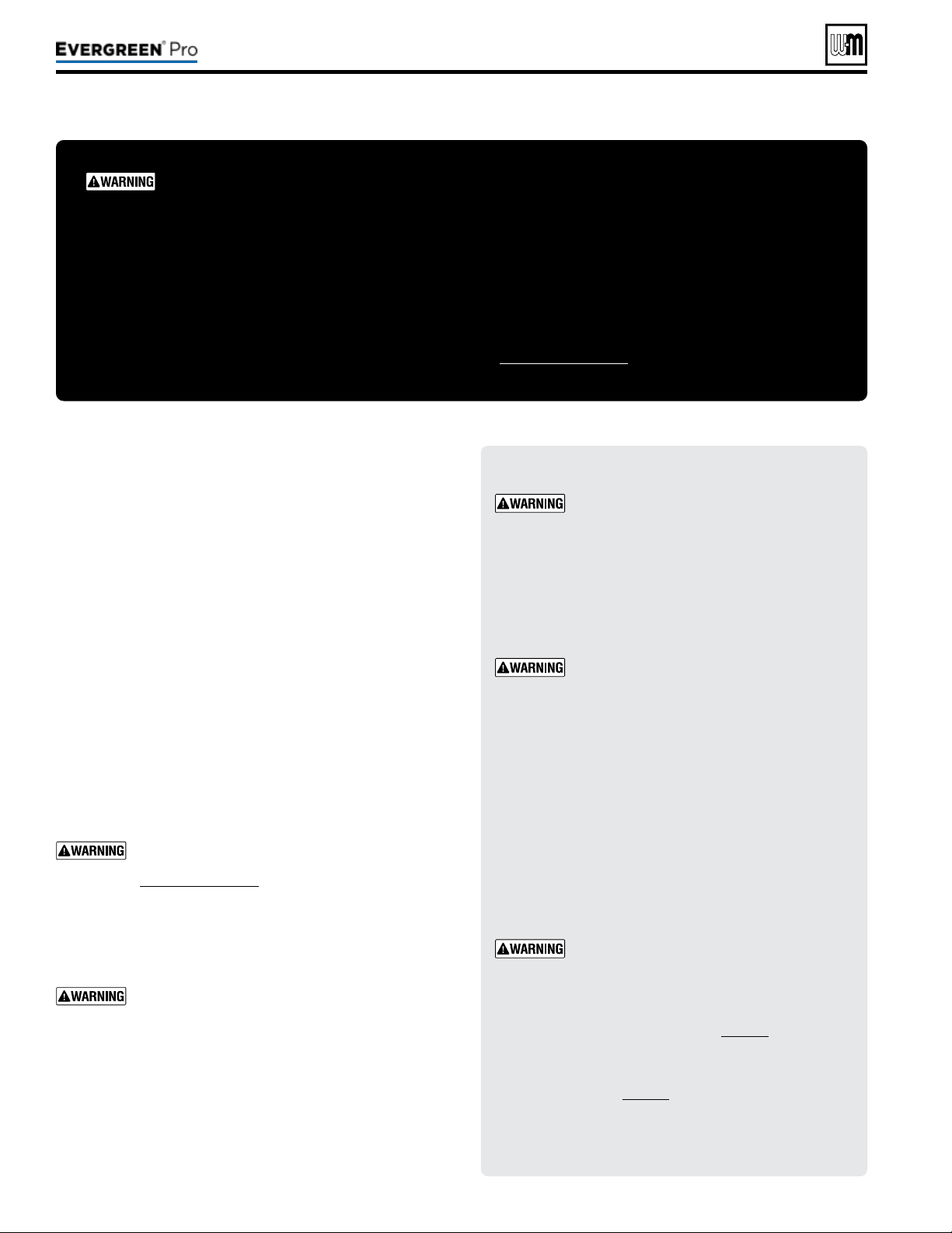
Part number 550-100-211/0122
– 110 –
1. Oil motors in system requiring regular oiling.
2. See Oiled bearing circulators for motor oiling procedures.
1. Check circulators in the system. Oil any circulators requiring
oil, following circulator manufacturer’s instructions. Over-
oiling will damage the circulator.
1. Isolate the boiler from the heating system.
2. Obtain Sentinel X400 cleaner from Weil-McLain. Follow
instructions supplied with the cleaner to clean the boiler
heat exchanger.
We recommend using the cleaning product
available from Weil-McLain, Sentinel X400. See
Replacement parts for ordering information.
Using other cleaning materials or methods could
cause permanent damage to the boiler heat ex-
changer.
Inspect the heating system water. If there is evi-
dence of sediment or corrosion, the boiler must
be isolated from the system. e system must then
be thoroughly cleaned to remove all sediment.
Isolate the cause of the system corrosion and cor-
rect the problem(s) before placing the boiler back
in s
ervice.
Failure to comply could result in severe personal
injury, death or substantial property damage.
DO NOT SERV I CE T H E BOI LER
WI THOUT AN Evergre en
®
MAINTENAN CE K I T AVAILABLE
e Evergreen
®
maintenance kit includes essential compo-
nents that must be replaced when accessing or disassembling
parts of the boiler.
Failure to replace damaged components and to use only the
parts specically intended for the boiler can result in severe
personal injury, death or substantial property damage.
See Figure111,page117 for part number.
Electrical shock hazard — Disconnect all elec-
trical power to the boiler before attempting
maintenance procedures. Failure to complete
could result in severe personal injury, death
or substantial property damage.
Reinstall boiler jacket door aer start-up or
servicing. e boiler front door must be se-
curely fastened to the boiler to prevent boiler
from drawing air from inside the boiler room.
is is particularly important if the boiler is
located in the same room as other appliances.
Inspect boiler jacket door gaskets. Gaskets
must be in good condition, with no tears or
gaps. Replace if necessary.
Failure to keep the door securely sealed and
fastened could result in severe personal injury
or death.
Removing and reinstalling components can
change boiler behavior. Aer any mainte-
nance procedure, you must prove the boiler
is operating correctly. To do so, follow the
complete procedure for boiler and system
start-up, beginning on page86.
After placing the boiler in operation, the
ignition system safety shuto device must be
tested, page91.
Failure to comply could result in severe per-
sonal injury, death or substantial property
damage.
220 /29 9/3 00 /39 9
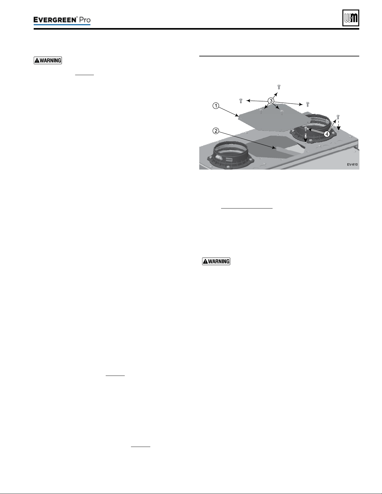
e boiler contains ceramic ber materials. Use
care when handling these materials per instructions
on page94 of this manual. Failure to comply could
result in severe personal injury.
1. Allen wrench, 3mm (T-wrench preferred).
2. 8mm socket with 8-inch extension.
3. Metric wrench or socket, 10mm.
4. T20 Torx.
5. 5/16” socket or nut driver.
6. Torque wrench.
7. Putty knife.
1. Shut down the boiler:
a. Follow “To Turn O Gas to Appliance” instructions on
boiler and Operating instructions.
b. Close the boiler manual gas valve.
2. Allow time for the boiler to cool to room temperature if it
has been ring.
3. Remove jacket front door by removing the two (2) latches at
the top of the jacket door.
4. Rotate and li the jacket door away from the boiler to remove.
5. See Figure106 (EVG220 shown).
a. Remove the burner access panel (item1) located on the
top of the boiler jacket by removing the screws (item3).
b. Remove the air bae (item2) and screws (item4) from
the jacket top as shown.
1. Carefully remove the ignition electrode assembly, following
the instructions in “Remove and inspect ignition electrode
assembly and wiring” on page97.
2. Set ignition electrode assembly and new gasket aside for
later re-insertion.
1. Carefully remove the ame sense rod assembly, following the
instructions in See instructions on page97 under “ Inspect
Flame Sense Rod”.
2. Set the ame sense rod with new gasket aside for later re-
insertion.
1. See Figure109,page115 (EVG220 shown).
2. Use a T20 Torx to remove the four (4) M4 screws (item10)
that secure the burner access cover (item4) to the heat ex-
changer cover plate (item6).
3. Remove the burner access cover (item4) and the burner
(item11).
Use caution when removing the burner to pull it
directly up and out. DO NOT angle the burner as
you remove it. Angling the burner could cause it to
strike the refractory, damaging the refractory and
causing fragments to fall into the heat exchanger.
Should this happen, a heat exchanger refractory
replacement kit must be installed and the heat ex-
changer must be thoroughly cleaned following the
procedures given in this manual and the refractory
replacement instructions.
4. Remove and discard the burner gasket (item12). is gasket
is graphite and may pull apartor stick to the burner on re-
moval. Use a so brush if necessary to remove residue. DO
NOT allow debris to drop into the heat exchanger. A new
gasket must be installed later when the burner is re-inserted.
5. Inspect the burner access cover seal (item13). Discard and
use a new seal during re-assembly if the seal is damaged in
any way.
6. Inspect the interior of the burner. Brush and vacuum the
interior if needed to remove lint or sediment. Alternative
cleaning methods:
a. Blow air or nitrogen from the inside out.
b. Clean with a water spray from inside the burner.
7. Inspect the burner exterior. It must be in good condition,
with no visible damage.
8. Clean the under side of the burner ange (see item15) with
a so brush to remove any gasket fragments remaining.
9. Set the burner aside for re-insertion later.
Figure106 Remove the burner access panel and screws
(1 and 3) and air bafe and screws (2 and 4)
from the jacket top as shown
Part number 550-100-211/0122
– 111 –
220 /29 9/3 00 /39 9

1. Look into the burner opening in the heat exchanger cover
plate.
2. Use a trouble light and inspection mirror to inspect the heat
exchanger interior.
a. Make sure that there is no debris inside the heat ex-
changer.
b. Use the inspection mirror to check the condition of the
burner refractory that is adhered to the bottom of the
heat exchanger cover plate. It must be in good condition
with no indication of damage or sagging.
c. Make sure there are no signs of overheating or of ue
gas leakage.
If visual inspection of the heat exchanger indicates
the need, follow the procedures in the following to
remove the heat exchanger cover plate and fully
inspect and clean the interior. Obtain replacement
parts for any components that may be damaged or
that show signs of leakage.
1. See Figure109,page115 partA to locate components refer-
enced in the following.
2. Remove the air silencer and disconnect gas line:
a. See Figure109,page115 partA and partB.
b. Locate the clips connecting the air silencer (item1) to the
venturi (item5). Gently pull clips out and away from the
venturi. While holding clips out, slide silencer back and
o of the venturi. Set the air silencer aside.
c. Disconnect the exible gas line where it connects just
below the gas valve (item3).Lay the free end of the ex-
ible gas line to the side.
Usetwowrenches when disconnecting the
exible gas line to prevent damage to the gas
valve and other gas line components.
d. Disconnect wire harness connected to the gas valve and
two wire harnesses connected to the blower.
3. Remove the blower/venturi/gas valve assembly.
a. See Figure109,page115, partA.
b. Remove the two (2) 8mm locknuts connecting the blower
and cover plate.
c. Gently set blower/venturi/gas valve assembly aside. In-
spect blower/cover plate gasket. If gasket appears dam-
aged, discard and replace with a new gasket.
The burner, igniter and flame sense
rod must be removed and inspected
followingthe procedures beginning on
page111.
4. Remove the heat exchanger cover plate:
a. See Figure109,page115 partA, partB and partC.
b. Use a 10mm wrench or socket to remove the nuts
(item9) that secure the heat exchanger cover plate
(item6) to the heat exchanger. [Six (6) nuts (EVG220)
or seven (7) nuts (EVG299/300/399).]
c. Carefully li the cover plate assembly straight up vertically
until the cover plate refractory (partD, item16) clears
the heat exchanger studs.
d. Pull the assembly forward and out of the jacket.
e. Turn the cover plate assembly over and place on a at
surface.
1. See Figure109,page115 partB and C.
a. Use a wide-blade putty knife to gently pry the refractory
from the heat exchanger cover plate. e refractory is at-
tached with silicone adhesive and should separate with a
little pressure on the putty knife.
DO NOT gouge or crack the refractory. e re-
fractory is made of ceramic ber materials. Read
the ceramic ber WARNING on page94 before
handling or disposing of ceramic ber materials.
b. Carefully scrape o any adhesive residue with the putty
knife, avoiding scratching or gouging the heat exchanger
cover plate surface.
c. Wipe o any residue, clean o the work table surface and
turn the cover plate over, bottom side on the work surface.
2. Remove the burner gasket (item12) from the heat exchanger
cover plate.
3. Clean the gasket surface with a so brush to remove any
gasket residue.
4. Lay the heat exchanger cover plate aside for re-installation
later.
1. Remove and discard the heat exchanger cover plate gasket.
a. e Maintenance Kit includes a new gasket for use when
re-installing the cover plate.
b. Clean o any residue on the heat exchanger cover plate
gasket surface.
2. See Figure109,page115 partD.
3. Use a strong light to visually inspect the interior of the heat
exchanger. Make sure the ueways (tubes) are clear and
unobstructed.
4. Use a vacuum cleaner to remove any accumulation on the
heating surfaces. is includes removing any pieces of cover
plate insulation assembly than may have dropped into the
exchanger.
DO NOT use any solvent when cleaning the heat-
exchanger.
Part number 550-100-211/0122
– 112 –
(continued)
220 /29 9/3 00 /39 9
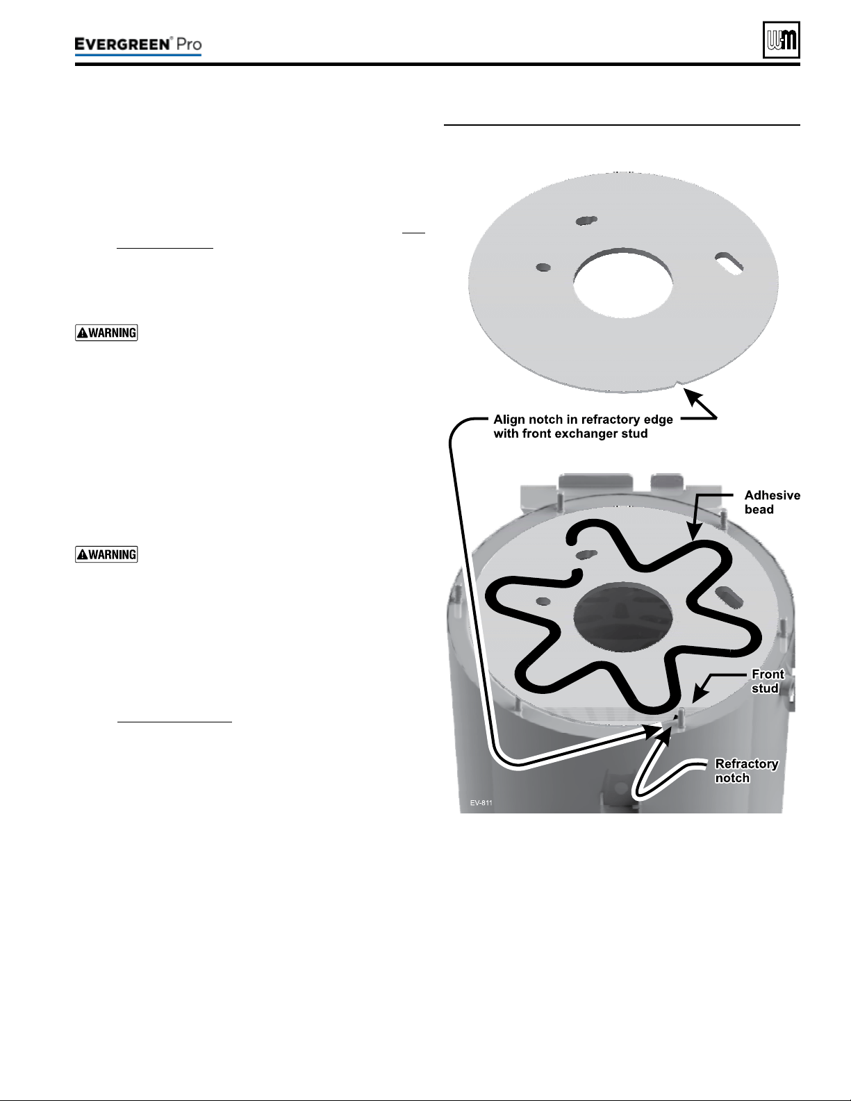
Figure107 Placing refractory into heat exchanger and
applying silicone adhesive – EVG 220 shown
5. If the vacuum cleaner is unable to clean completely, wash the
heating surfaces with clean, warm water,using the following
procedure.
a. Place a shallow pan under the boiler condensate drain
connection.
b. Loosen the condensate trap clamp (item22) and slide
the drain line off of the drain connection. (See Fig-
ure109,page115 for reference.)
c. Spray water into the heat exchanger and tubes to remove
sediment. Collect water in pan below.
d. If additional cleaning is necessary, use a pressure washer
(using caution) to obtain better scrubbing action.
Do not attempt to use hard objects to clean out the
exchanger or tubes. e heat exchanger surfaces
could be damaged.
1. See Figure107 for reference.
2. Obtain the new refractory from the Maintenance Kit.
3. Carefully place the refractory into the top of the heat ex-
changer as shown.
4. Align the notch in the refractory with the front heat exchanger
cover plate stud (just right of center in the front).
DO NOT press down on the refractory. Too much
force could cause the refractory to crack or be dam-
aged.
5. Use the silicone adhesive to lay a bead of silicone in a weaving
pattern as shown.
a. Maintain at least 1inch clearance from edges of refractory
and from openings in refractory.
b. Do not apply an excessive amount of adhesive. is could
cause spreading or prevent good contact with the cover
plate.
6. See Figure109,page115 for reference.
7. Re-install the heat exchanger cover plate using the following
procedure.
a. Place the heat exchanger cover plate gasket, item17, (in
Maintenance Kit) onto the heat exchanger studs.
b. Carefully place the heat exchanger cover plate over the
heat exchanger cover plate studs.
c. Gently lower the cover plate until it rests on the cover
plate gasket.
d. Reach into the cover plate burner opening and gently pull
the refractory up against the cover plate to compress the
adhesive for a good seal/adhesion.
e. Use a 10mm wrench or socket to secure the nuts
(item9) on studs of the heat exchanger cover plate
(item6) to the heat exchanger. [Six (6) nuts (EVG220)
or seven (7) nuts (EVG299/300/399).]
f. Tighten the cover plate nuts gradually, adjusting a little
at a time. Use criss-cross pattern and repeat until all are
tightened evenly.
g. Use a torque wrench to tighten the cover plate nuts, to a
torque of 57inch-pounds.
Part number 550-100-211/0122
– 113 –
220 /29 9/3 00 /39 9
(continued)

Figure108 Legend for Figure 109, page 115
A Boiler interior assembled view,
B Boiler interior exploded view, showing heat exchanger
cover plate (item6) blower, burner assembly, burner
access cover seal (item13), ignitor, ame sense rod,
and sight glass.
C Blower, burner, and venturi, showing combustion
chamber cover plate insulation assembly (item16)
D Heat exchanger interior
E Boiler lower interior, showing condensate dish
(item19) and condensate drain line (item22)
1 Inlet air silencer
2 Blower assembly
3 Gas valve
4 Burner access cover
5 Venturi assembly
6 Heat exchanger cover plate
7 Igniter assembly
8 Flame sense rod
9 Heat exchanger cover plate retainer nuts (6) - EVG
220, and (7) - EVG 299/300/399.
10 Burner cover retainer screws, M4 Phillips with captive
washers
11 Burner
12 Burner gasket
13 Burner access cover seal
14 Burner gasket sealing surface
15 Burner sealing surface (lower surface of burner
ange)
16 Combustion chamber refractory (adhered to
combustion chamber cover plate with silicone
adhesive)
17 Heat exchanger cover plate gasket
18 Sight glass assembly
19 Heat exchanger outer shell
20 Condensate dish
21 Condensate dish joint
22 Condensate drain line clamp
23 Condensate drain line
1. See Figure109,page115
for reference.
2. Obtain the new burner gasket (item12) from the Maintenance Kit
and install into the heat exchanger cover plate.
3. Reinstall the burner (item 11), and burner access cover seal
(item13) on the heat exchanger cover plate (item6).
a. Insert and tighten the burner access cover screws (item10)
using a T20 Torx. Tighten screws gradually, adjusting a little
at a time, using a criss-cross pattern and repeating until all are
tightened evenly. e screws must be secure, with
b. Use a torque wrench to tighten screws to a torque of 23inch-
pounds.
4. Reinstall the igniter assembly (item7).
a. Insert the igniter into the cover plate opening, with the new
gasket in position.
b. Reinstall the two (2) Allen head screws nger tight.
c. Use a torque wrench to tighten screws to a torque of 20inch-
pounds.
d. Reconnect the ignition cable and the igniter ground wire.
5. Reinstall the ame sense rod (item8).
a. Carefully insert the ame sense rod into the cover plate open-
ing, with the new gasket in position.
b. Use a torque wrench to tighten screws to a torque of 20inch-
pounds.
c. Re-attach the wire harness to the ame sense rod.
6. Reconnect the exible gas line to the gas valve using two wrenches.
7. Reinstall the blower/venturi/gas valve assembly:
a. Install the two (2) 8mm locknuts connecting the blower to
the cover plate.
b. Use a torque wrench to tighten locknuts to a torque of 20inch-
pounds.
8. Reinstall the air inlet silencer (item1) by pressing onto the ven-
turi (item5). Reinstall the air inlet silencer by gently pushing the
silencer onto the venturi. If needed, gently pull apartthe clips to
clear venturi.
9. Reconnect the wire harnesses to the blower and gas valve.
10. Reinstall the condensate trap on the boiler condensate drain con-
nection. (See Figure109,page115 partE for reference.)
11. Reinstall the burner access panel and air baffle (see
Figure106,page111). Tighten screws securely.
Perform a complete start-up procedure when putting the
boiler back into service. See page92 and all instructions
for start-up and verication. Include a soap suds leak test
on all interior and exterior gas piping aer starting the
boiler.
Aer placing the boiler in operation, the ignition system
safety shuto device must be tested, page91.
Part number 550-100-211/0122
– 114 –
(continued)
220 /29 9/3 00 /39 9
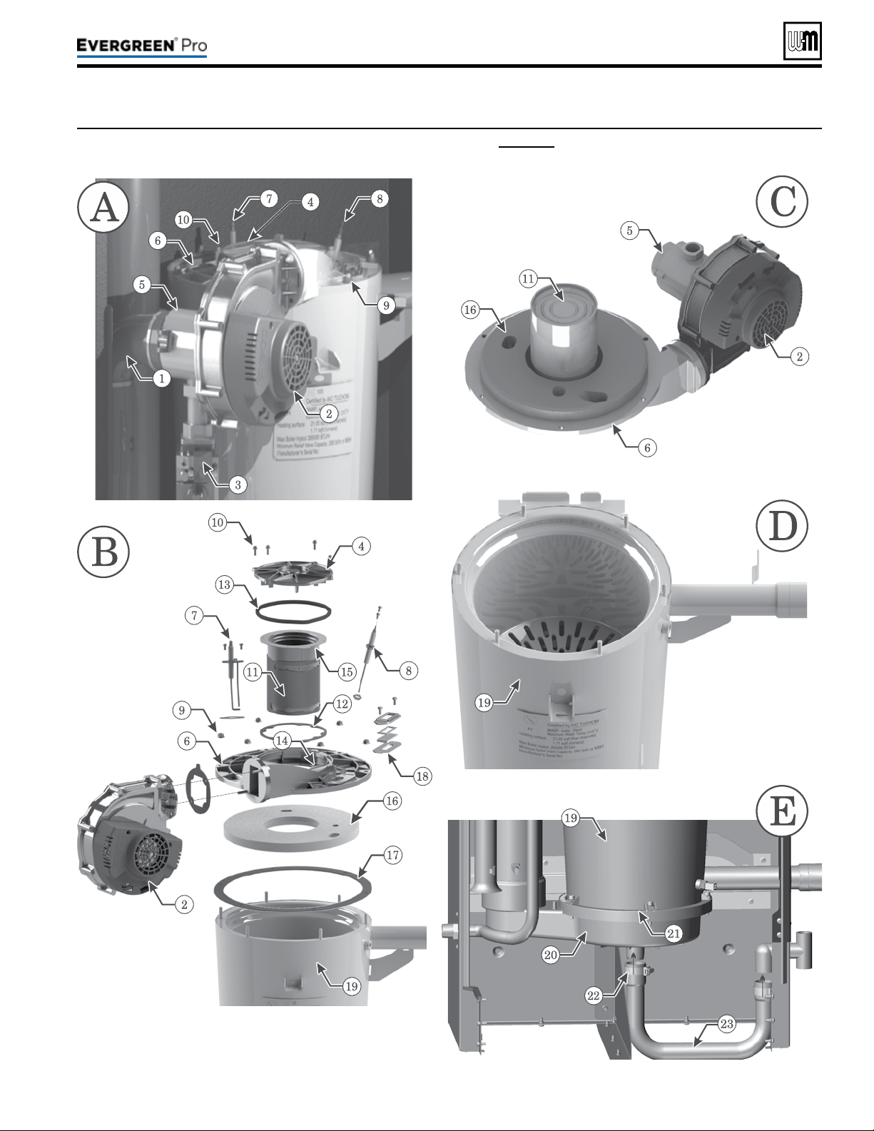
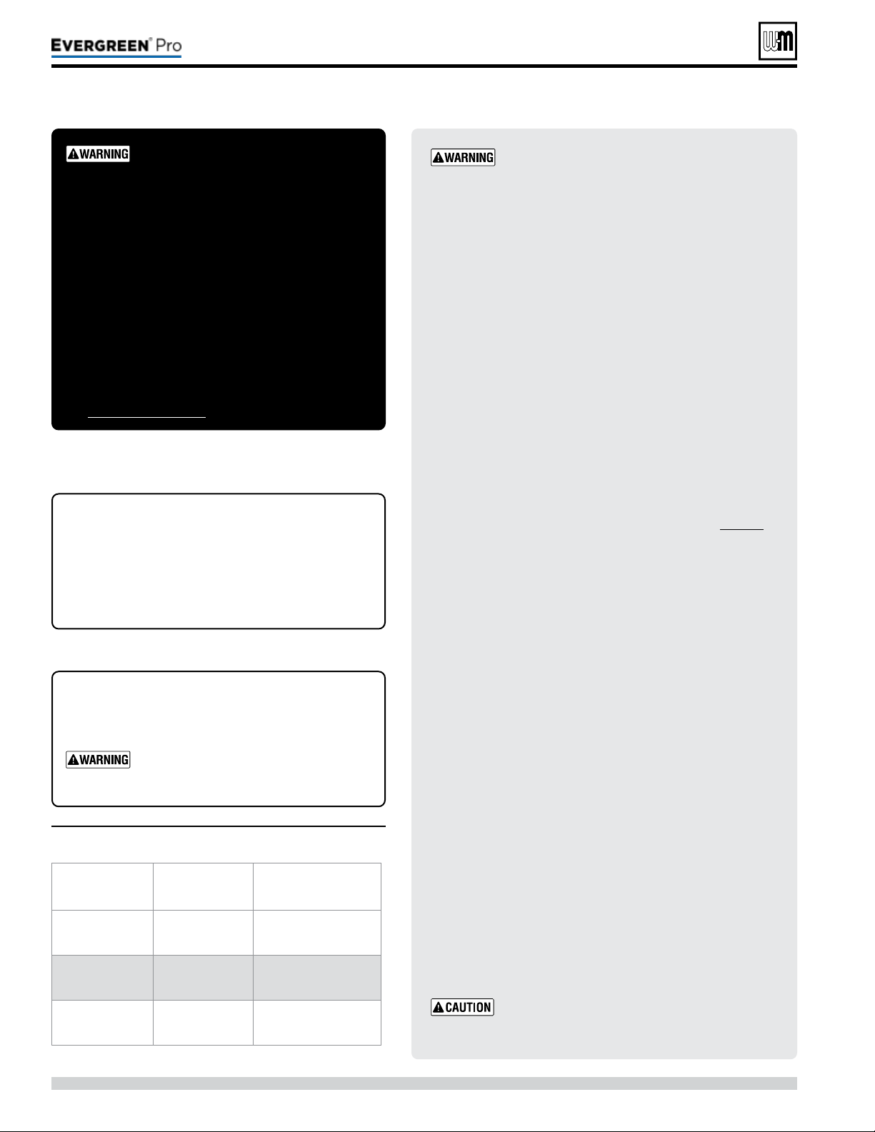
Gotowww.weil-mclain.comtolocateWeil-McLaindistributors
Part number 550-100-211/0122
– 116 –
DO NOT SERV I CE T H E
BOI LER WITHOUT A
Eve rgre e n
®
M AI N TEN ANCE
KIT AVAI LABLE
e
Evergreen
®
maintenance kit includes compo-
nents that may have to be replaced when accessing
or disassembling parts of the boiler. Failure to replace
damaged components and to use only the parts spe-
cically intended for the boiler can result in severe
personal injury, death or substantial property damage.
See Figure111,page117 for part number.
Failuretoadheretotheseguidelinescan
resultinseverepersonalinjury,deathor
substantialpropertydamage.
Replacement parts must be purchased through a local
Weil-McLain distributor. When ordering, specify boiler model
and size and include description and part number of replace-
ment part. Results from using modied or other manufactured
parts will not be covered by warranty and may damage boiler
or impair operation.
THE BOI LER CONTAINS CERAM IC
FIBER M ATERIALS
The boiler contains ceramic ber materials. Use care
when handling these materials per instructions on page94 of
this manual. Failure to comply could result in severe personal
injury.
REIN STALL JACKET DOOR
Inspect boiler jacket door gaskets and reinstall boiler jacket
front door aer start or servicing. e boiler door must be
securely fastened to the boiler to prevent boiler from drawing
air from inside the boiler room. is is particularly important
if the boiler is located in the same room as other appliances.
Failure to keep the door securely fastened could result in severe
personal injury or death.
ALWAYS TURN POWEROFFTOTHEBOILERTO
PREVENT ELECTRICALSURGES, WHICH CAN
DAMAGEBOILERCOMPONENTS.
LABEL WIRES BEFORE REMOVIN G
Label all wires prior to disconnection when
servicing controls. Wiring errors can cause im-
proper and dangerous operation.
Figure110 Propane conversion kits
Boiler
model
Kit
partnumber
Installation
instructions
EVG 220
540-202-849
See
page 12
EVG299/300
540-202-841
See
page 12
EVG 399
540-202-842
See
page 12
REPLACEMENT PART NU MBERS
Weil-McLainpartnumbersarefoundinthis
manualandinWeil-McLain Boilers and Con-
trols Repair Parts Lists.
WHEN OPERATI N G THE BOI LER
ON PROPANE GAS
ALL Evergreen
®
boilers must be
converted in order to operate with
propanegas
.
220 /29 9/3 00 /39 9
Figure111 Miscellaneous parts and kits
Gotowww.weil-mclain.comtolocateWeil-McLaindistributors
Part number 550-100-211/0122
– 117 –
220 /29 9/3 00 /39 9
(continued)
Description
PartNumber
Antifreeze, Sentinel X500 (1 gal) . . . . . . . . .
Antifreeze, Sentinel X500 (5 gal) . . . . . . . . .
Corrosion inhibitor, Sentinel X100 . . . . . . . . .
Sentinel X100 Quick Test Kit. . . . . . . . . . . .
Cleaner, Sentinel X400 . . . . . . . . . . . . . .
592-900-029
592-900-006
592-900-002
592-900-005
592-900-003
Evergreen
®
Inspection kit —
igniter gasket, ame sense gasket, burner gasket,
burner access cover seal, and hardware
383-900-097
Evergreen
®
220 maintenance kit — ame sense
rod, ame sense gasket, igniter, igniter gasket, venturi
gasket, cover plate gasket, venturi-gas valve o-ring,
refractory, silicone, inhibitor test kit, burner access
cover seal, and hardware
383-900-071
Evergreen
®
299/300 maintenance kit — ame sense
rod, ame sense gasket, igniter, igniter gasket, venturi
gasket, cover plate gasket, venturi-gas valve o-ring,
refractory, silicone, inhibitor test kit, burner access
cover seal, and hardware
383-900-072
Evergreen
®
399 maintenance kit — ame sense
rod, ame sense gasket, igniter, igniter gasket, venturi
gasket, cover plate gasket, venturi-gas valve o-ring,
refractory, silicone, inhibitor test kit, burner access
cover seal, and hardware
383-900-088
Wall-mount kit — wall mount bracket and hardware 383-900-074
Condensate drain tube - EVG 220
Condensate drain tube - EVG 299/300/399
560-907-767
560-907-768
Low water cut-off w/test button, Kit 383-500-643
Relief Valve (80 psi) and P&T Gauge Kit 383-900-082
Condensate neutralizer kit 383-500-631
Direct Exhaust Kit
(Includes mounting plates for intake and exhaust for
inside and outside, vent screen 3 & 4 Inch, Template
vent/air termination hole, and mounting hardware) 383-500-769
Weil-McLain sidewall vent/air cap termination kit for
PVC vent and air pipes (Includes W-M sidewall vent/air
termination cap, inside and outside cover plates, and
mounting hardware)
(EVG 220) – 3” Kit
(EVG 220, 299, 300 & 399) – 4” Kit
383-500-397
383-500-398
Description
PartNumber
Sidewall separate pipes vent/air termination kits
(includes two cover plates)
Kit for 3” or 4” PVC vent and air pipes . . . . . . .
383-500-100
PVC concentric vent kit — horizontal or vertical
(includes components for concentric assembly)
Kit for 3” PVC vent and air pipes. . . . . . . . . .
Kit for 4” PVC vent and air pipes. . . . . . . . . .
383-500-350
383-900-075
IPEX PVC concentric vent kit — available from
IPEX
Kit for 3” PVC vent and air pipes. . . . . . . . . .
Kit for 4” PVC vent and air pipes. . . . . . . . . .
196006(L=20”)
196106(L=32”)
196116(L=44”)
196021
Bird screens (2 required)
For 3” PVC vent and air pipes . . . . . . . . . . .
For 4” PVC vent and air pipes . . . . . . . . . . .
383-500-105
383-500-110
M&G Simpson-Duravent PolyPro VERTICAL
concentric vent/air kit; — available from
vent manufacturer
3” polypropylene pipe (Black) . . . . . . . . .
(Terra Cotta) . . . . . .
4” polypropylene pipe (Black) . . . . . . . . . .
(Terra Cotta) . . . . . .
3PPS-VKL
3PPS-VK-TCL
4PPS-VKL
4PPS-VK-TCL
PP Appliance Adapters; — available from
vent manufacturer
4” M&G Simpson-Duravent . . . . . . . . . .
4” Centrotherm INNOFLUE. . . . . . . . . . .
4PPS-04PVCM-
4PPF
ISAAL040Y
Centrotherm INNOFLUE VERTICAL concentric vent/air
kit; — available from
vent manufacturer
3” polypropylene pipe . . . . . . . . . . . . .
4” polypropylene pipe . . . . . . . . . . . . .
ICRT3539
ICRT4679
System Immersion Temperature Sensor
(2 required)
511-724-299
Protonode Conversion Kit –Bacnet 383-600-322
Gotowww.weil-mclain.comtolocateWeil-McLaindistributors
Part number 550-100-211/0122
– 118 –
(continued)
Item Name Description/contents
PartNumber
100 Front door (Includes W-M badge and door gaskets) 383-900-171
120 Wall-mount bracket (jacket side) (Includes screws) 383-900-086
130 Door latch (2 required) (Includes rivets) 383-700-122
140 Gasket kit (Includes ue pipe gaskets and condensate dish gasket)
See P.120 for 220
see P.122 for 299/300/399
150 Flue pipe adapter Top ue adapter with internal gasket 383-900-014
160 Boiler ue pipe Internal ue pipe and gasket 383-900-015
170 Air inlet adapter Top air inlet adapter with internal gasket 383-900-013
180 Gasket - pipe adapter to cabinet Gasket - ue adapter to cabinet 383-900-058
190 Gasket - pipe adapter to system pipe Gasket ts inner diameter of top adapter 590-318-106
200 Jacket panel bottom (Includes bottom gasket, leveling legs and screws) 383-900-042
210 Jacket panel top (Includes top gasket and screws) 383-900-043
230 Jacket panel back (Includes brackets, gaskets, door latches and screws) 383-900-044
250 Bracket piping (2 required) (Includes screws) 383-900-085
260 Air bafe (Includes screws) 383-900-084
280 Grommet sealing (2 required) Sealing water pipes to cabinet 562-248-762
290 Bracket mounting heat exchanger (Includes screws) 383-900-087
300 Panel - burner access (Includes hardware) 383-900-041
310 Pressure switch Set point 3.25 W.C. 383-900-080
320 Tube - pressure switch 590-300-056
Figure112 Jacket parts — Evergreen
®
2 2 0 /2 9 9 /3 0 0 /3 9 9 (see Figure 113, page 119 for illustration)
220 /29 9/3 00 /39 9
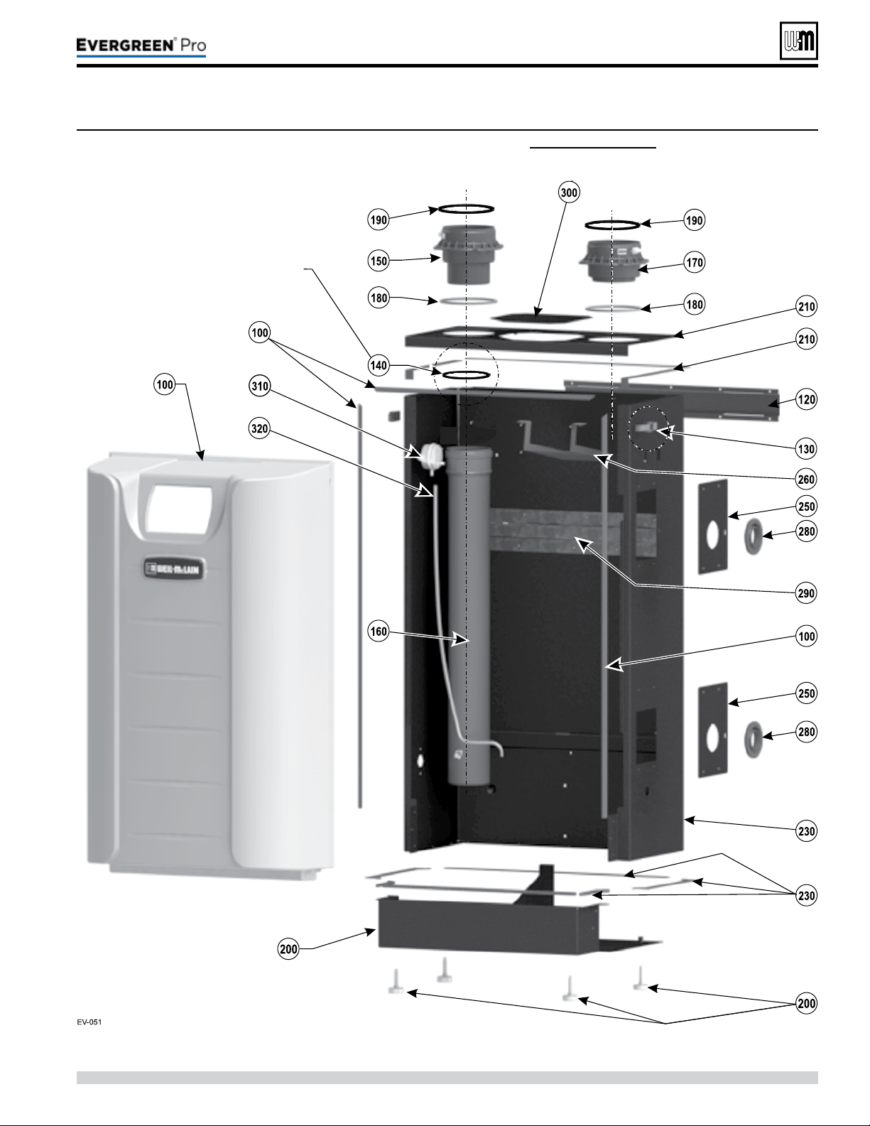
Gotowww.weil-mclain.comtolocateWeil-McLaindistributors
Part number 550-100-211/0122
– 119 –
220 /29 9/3 00 /39 9
(continued)
Figure113 Jacket assembly — Evergreen
®
2 2 0 /2 9 9 /3 0 0 /3 9 9 (see Figure 112, page 118 for part numbers)
Gasket shown is provided in
Item 130, pages 121 and 123
Gasket Kit P/N 383-900-028
Gotowww.weil-mclain.comtolocateWeil-McLaindistributors
Part number 550-100-211/0122
– 120 –
(continued)
Figure114 Heat exchanger parts Evergreen
®
2 2 0 (see Figure 115, page 121 for illustration)
Item Name Description/contents
PartNumber
100 Heat exchanger, gaskets and hardware (Includes items 130 and 150) 383-900-025
110
Heat exchanger, condensate dish, cover plate, burner,
igniter, sight glass, refractory, water sensors, gaskets,
silicone, and hardware
(Includes items 120 through 280) 383-900-069
120 Condensate dish, gaskets, and hardware (Includes item 130) 383-900-012
130 Gasket to seal heat exchanger to condensate dish (Includes ue pipe gaskets) 383-900-028
150
Refractory insulation & silicone sealant, igniter gasket,
ame rod gasket and burner gasket
383-900-032
160
Heat exchanger cover plate, refractory, silicone, gaskets
and hardware
(Includes items 150, 190, and 270) 383-900-016
170 Flame sense rod kit (Includes ame sense rod, gasket and screws) 383-900-094
190 Sight glass kit (Includes bracket, glass, gaskets, and hardware) 383-900-099
220 Igniter kit (Includes igniter, gasket and screws) 383-900-033
240 Burner kit (Includes item 280, burner, gaskets and screws) 383-900-022
260 Heat exchanger water temperature sensor (2 required)
(One sensor for either boiler inlet or outlet water
temperature)
511-724-296
270 Burner access cover, seal and hardware (Includes item 280) 383-900-019
280 Burner access cover seal, burner gasket and hardware 383-900-010
220 /29 9/3 00 /39 9
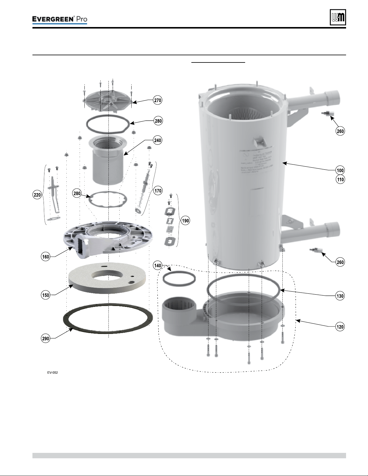
Part number 550-100-211/0122
– 122 –
(continued)
Figure116 Heat exchanger parts Evergreen
®
2 9 9 /3 0 0 /3 9 9 (see Figure 117, page 123 for illustration)
Item Name Description/contents
PartNumber
Model
299/300
Model
399
100 Heat exchanger, gaskets and hardware (Includes items 130, and 150)
383-900-024
—
383-900-023 —
110
Heat exchanger, condensate dish, cover plate,
burner, igniter, sight glass, refractory, water
sensors, gaskets, silicone, and hardware
(Includes items 120 through 280)
383-900-068
—
383-900-067 —
120 Condensate dish, gaskets, and hardware (Includes item 130) 383-900-011
130 Gasket to seal heat exchanger to condensate dish (Includes ue pipe gaskets) 383-900-030
150
Refractory insulation & silicone sealant, igniter
gasket, ame rod gasket and burner gasket
383-900-031
—
383-900-096 —
160
Heat exchanger cover plate, refractory, silicone,
gaskets, and hardware
(Includes items 150, 190, and 270)
383-900-017
—
383-900-095 —
170 Flame sense rod kit
(Includes ame sense rod, gasket
and screws)
383-900-094
190 Sight glass kit
(Includes bracket, glass, gaskets,
and hardware)
383-900-099
220 Igniter kit (Includes igniter, gasket and screws) 383-900-033
240 Burner kit
(Includes item 280, burner, gaskets
and screws)
383-900-021
—
383-900-020 —
260
Heat exchanger water temperature sensor
(2 Required)
(one sensor for either boiler inlet or
outlet water temperature)
511-724-296
270 Burner access cover, gaskets and hardware (Includes item 280) 383-900-018
280
Burner access cover seal, burner gasket and
hardware
383-900-010
220 /29 9/3 00 /39 9

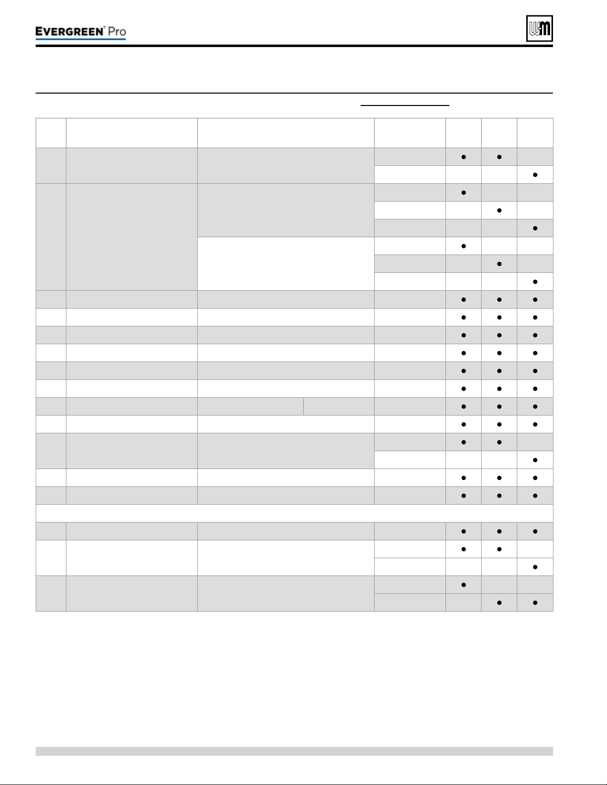
Figure118 Piping components for Evergreen
®
2 2 0 /2 9 9 /3 0 0 /3 9 9 (see Figure 119, page 125 for illustration)
Gotowww.weil-mclain.comtolocateWeil-McLaindistributors
Part number 550-100-211/0122
– 124 –
(continued)
Item Name Description / contents
PartNumber
Model
220
Model
299/300
Model
399
100 Gas valve Gas valve, gasket, and o-ring
383-900-027
—
383-900-061 — —
120 Venturi
Natural gas
(Includes 150 and 240)
383-900-054 — —
383-900-055 — —
383-900-056 — —
Liqueed Petroleum (Propane) Gas
(Includes 150 and 240)
540-202-849 — —
540-202-841 — —
540-202-842 — —
140 Adapter gas pipe ¾”NPT Gas pipe adapter between gas valve and venturi 562-302-584
150 Gas pipe gasket For sealing between adapter and venturi 562-248-765
160 Gas valve adapter block Threaded block, o-ring and screws (2 required) 383-900-026
170 Gas ex line adapter Connection between gas valve and gas line 562-302-583
180 Gas line Gas line between gas valve and cabinet 560-907-766
190 Gas line gasket Gas line seal to cabinet 590-318-085
200 Blower Blower Complete Blower 383-900-039
210 Blower gasket Blower to cover plate seal 383-900-036
220 Inlet air silencer Silencer with gasket
383-900-034 —
383-900-035 — —
230 O-ring -gas valve (2 required per assembly) 590-318-043
240 O-ring -blower O-ring between blower and venturi 590-318-102
300 Pressure & temperature gauge Shipped loose for eld installation 380-000-000
310 Relief valve
30 PSIG relief valve —
shipped loose for eld installation
383-500-095 —
383-900-076 — —
320 Condensate drain trap (not shown)
540-131-075 — —
540-131-076 —
220 /29 9/3 00 /39 9
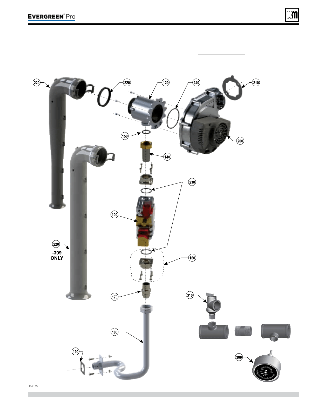
Gotowww.weil-mclain.comtolocateWeil-McLaindistributors
Part number 550-100-211/0122
– 126 –
Item Name Description / contents
PartNumber
100 Flue temperature sensor One sensor with gasket 383-500-600
110 Outdoor temperature sensor One sensor 510-312-218
120 System temperature sensor (2 required) 383-500-601
130 Low water cutoff Low water cutoff 383-500-643
140 Transformer 120v/24v 50-60 Hertz transformer 511-802-011
150 Control assembly Ignition control module 381-330-020
160 On/off power switch 20 Amp rated 511-624-645
170 Comm circuit board 383-900-089
180 Display board assembly (Includes circuit board, communication cable and plastic housing) 383-900-078
190 Control tray Plastic electrical enclosure (Includes gaskets and hardware) 383-900-079
200 Cover (Includes gaskets and hardware) 383-900-029
240 Inspection window plug 591-491-217
250
F1 - 3 amp 120VDC, fast blow ato
(not shown here — see Figure 97, page 103)
5 Fuses (used for boiler circulator) 383-900-081
260
F2 - 3 amp 32VDC, fast blow ato
(not shown here — see Figure 98, page 103)
5 Fuses (used for low voltage circuit) 383-500-603
270
F3 - 12 amp 250 Volt, fast-blow ag
(not shown here — see Figure 98, page 103)
5 Fuses (used for line voltage circuit) 383-500-604
280 Wire harness — High voltage Wire harness (not shown) 591-392-007
290 Wire harness — Low voltage Wire harness (not shown) 591-392-008
300 Wire harness — Communication Ethernet Wire harness (not shown) 591-392-009
310 Wire harness — Low voltage Comm. board Wire harness (not shown) 591-392-010
320 Wire harness — Blower Wire harness (not shown) 591-392-011
330 Wire harness — Control/display comm. Wire harness (not shown) 383-500-633
340 Wire harness — with receptacle and safety cap Wire harness (not shown) 383-500-638
350 Ignition cable Ignition cable (not shown) 591-392-012
360 Terminal block kit
Includes 1 high voltage terminal block, low voltage terminal
blocks and screwdriver (not shown)
383-900-083
370 Gasket - display support 590-318-107
380 Cover ground terminal kit (not shown) 383-900-098
390 Gasket - ue temperature sensor 590-318-011
400
Circulator Evergreen 220/299/300
Circulator Evergreen 399
Taco Pump 0014
Taco Pump 0013
511-405-133
511-405-140
Figure120 Controls & electrical components — Evergreen
®
2 2 0 /2 9 9 /3 0 0 /3 9 9 (see Figure 121, page 127 for illustration)
(continued)
220 /29 9/3 00 /39 9
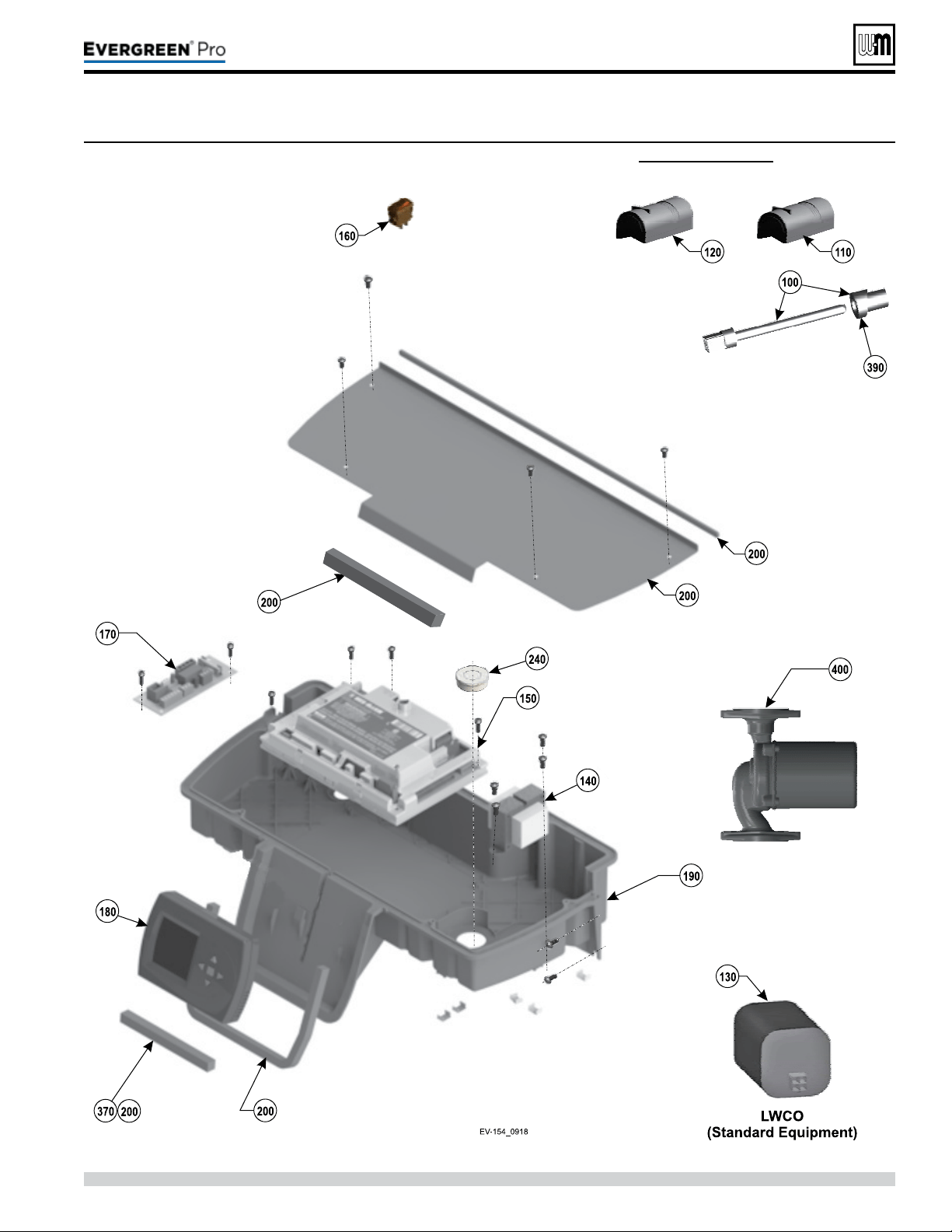
Gotowww.weil-mclain.comtolocateWeil-McLaindistributors
Part number 550-100-211/0122
– 127 –
220 /29 9/3 00 /39 9
Figure121 Controls & electrical assemblies — Evergreen
®
2 2 0 /2 9 9 /3 0 0 /3 9 9 (see Figure 120, page 126 for part numbers)
(continued)

Part number 550-100-211/0122
– 128 –
Figure122 Dimensional data — Evergreen
®
2 2 0 /2 9 9 /3 0 0 /3 9 9 (all dimensions in inches)
1 Boiler supply tapping — 1½”NPT.
2 Boiler return tapping — 1½”NPT.
3 Control panel, with display and navigation buttons.
4 Electrical entrance openings.
5 Vent connection: 4” PVC.
6 Gas connection – ¾” NPT (manual gas valve shipped
loose for eld installation) See page51 for details and
instructions.
7 Condensate drain connection.
8 Air connection: 4” PVC.
220 /29 9/3 00 /39 9
FRONT
LEFT RIGHT
TOP
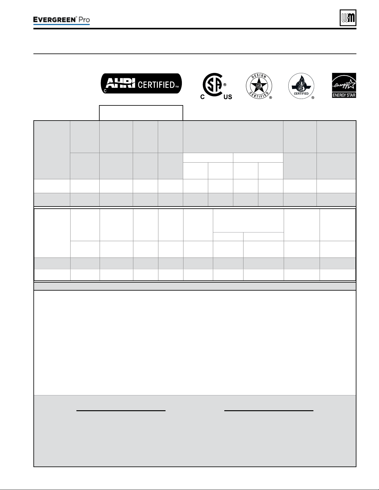
DOE
Part number 550-100-211/0122
– 129 –
220 /29 9/3 00 /39 9
Figure123 Ratings and engineering data — Evergreen
®
220/299/300/399
AHRI Certied Ratings
Boiler
Model
Input
Heating
Capacity
Seasonal
Efciency
Net
Water
Rating
% Input derate vs vent length
(Values shown are at MAX vent/air pipe
length —
See Note 6)
DirectVentVentingONLY
Boiler
Water
Content
Vent/
Comb.Air
Connection
Diameter
Btuh
(Note 5)
MBH
(Note 2)
AFUE, %
(Note 1)
MBH
(Note 3)
Natural gas Propane
Gallons
Inches
(Note 4)
3”
Vent/air
piping
4”
Vent/air
piping
3”
Vent/air
piping
4”
Vent/air
piping
EVG 220
220,000 206 95.0 179 7.2% 2.1% 7.2% 2.1% 4.6 3 or 4" PVC
EVG 299
299,000 280 95.0 243
N/A 2.7% N/A 2.7% 7.0 4" PVC
Notes
1 As an Energy Star Partner, Weil-McLain
has determined that Evergreen
® 220
and 299 boilers meet the Energy Star
guidelines for energy eciency.
NOTE: Adjusting boiler ring rate will
aect AFUE rating.
2 Based on standard test procedures
prescribed by the United States Depart-
ment of Energy. Ratings also referred to
as CSA Output.
NOTE that only DOE Heating Capacity
and AFUE are certied by AHRI. AFUE
is also know as Annual Fuel Utilization
Eciency or Seasonal Eciency.
3 Net AHRI ratings are based on net
installed radiation of sucient quantity
for requirements of the building and
nothing need be added for normal pip-
ing and pickup. Ratings are based on a
piping and pickup allowance of 1.15. An
additional allowance should be made
for unusual piping and pickup loads.
4 Evergreen
®
boilers are designed to be be
direct-vented. Evergreen
®
boilers require
special venting, consistent with Catego-
ry IV boiler. Use only the vent materials
and methods specied in this manual.
Evergreen
®
boilers may be direct exhaust
vented.
Evergreen
®
220 vent/air pipes can be
either 3” or 4”. Evergreen
®
299/300/399
vent/air pipes must be 4”.
All vent and air pipe elbows must
be sweep elbows, NOT short-radius
elbows.
5 Ratings shown are for sea level ap-
plications only. For altitudes from sea
level to 2000 feet above sea level, the
Evergreen
®
boiler requires no modica-
tions. e boiler automatically derates
itself by approximately 4% per 1000 feet
above sea level.
6 All of the boilers will automatically
de-rate as vent/air pipe length increases,
due to the pressure loss through the
piping. For vent/air pipe lengths less
than the maximum, the derate equals
the value above times vent length ÷ 100.
THEOU T DOOR SEN SORSUPPLIEDWITHTHEBOILERMUSTBEINSTALLEDUNLESSEXEMPTEDBELOW:
I MPORTANT
In accordance with Section 303 of the
2007EnergyAct, this boiler is equipped
with a feature that saves energy by reducing
the boiler water temperature as the heating
load decreases. is feature is equipped with
an override which is provided primarily to
permit the use of an external energy manage-
ment system that serves the same function.
THISOVERRIDEMUSTNOTBEUSEDUNLESSATLEASTONEOFTHEFOLLOWING
CONDITIONSISTRUE:
• An external energy management system is installed that reduces the boiler water temperature as the
heating load decreases.
• is boiler is not used for any space heating.
• is boiler is part of a modular or multiple boiler system having a total input of 300,000 BTU/hr or
greater.
• is boiler is equipped with a tankless coil (not applicable to Evergreen
®
).
Boiler
Model
CSA
Input
Gross
Output Net Rating
Combustion
Efciency
Thermal
Efciency
% Input derate vs vent length
(Values shown are at MAX vent/air
pipe length —
See Note 6)
DirectVentVentingONLY
Boiler
Water
Content
Vent/
Comb.Air
Connection
Diameter
Natural gas Propane
Btuh
(Note 5)
MBH
(Note 5)
MBH
(Note 3)
%
(Note 5)
%
(Note 5)
4”
Vent/air
piping
4”
Vent/air
piping
Gallons
Inches
(Note 4
EVG 300
300,000 286 248 96.0 95.5 2.7% 2.7% 7.0 4” PVC
EVG 399
399,000 383 333 96.5 96.0 4.3% 4.3% 6.7 4” PVC
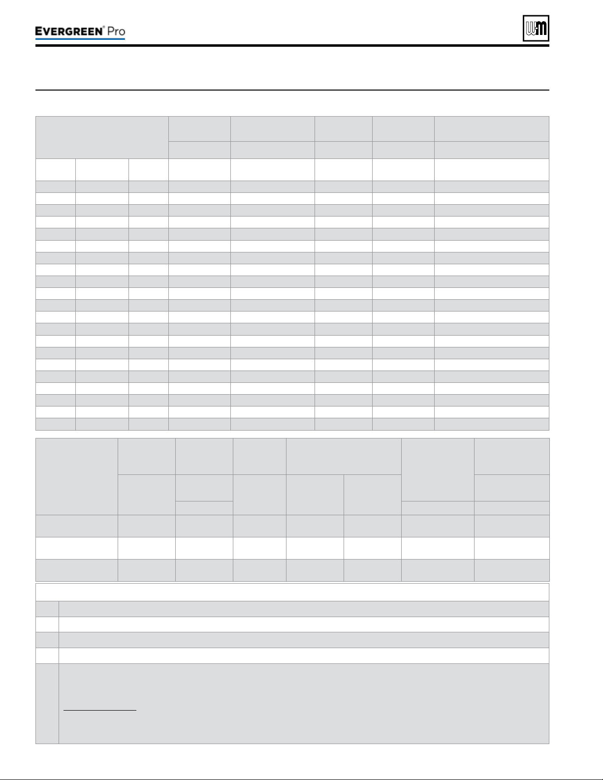
Part number 550-100-211/0122
– 130 –
Boiler
Model
Shipping
weight
Operating
weight
Water
content
Waterowrate
perboiler
Vent/airpipe
size:
(Provide a
separate vent for
each boiler)
Electrical
service
required
Pounds
per boiler
Pounds
per boiler
Gallons
per boiler
GPM
@ 20°F rise
GPM
@ 40°F rise
Amps
per boiler
Note 4 Note 5 Note 3
EVG 220 215 190 4.6 22 11 3” or 4” 15.0
EVG299/300 260 255 7.0 30 15 4” 15.0
EVG 399 260 255 6.7 40 20 4” 15.0
Notes
Based on standard test procedures outlined by DOE for individual boilers.
2
Net water ratings are based on piping and pickup allowance of 1.15. Consult Weil-McLain Technical Services for other allowances.
3
Total amp requirement includes up to three circulators, not exceeding 2.2 amps per circulator.
Operating weight is the total weight of the boiler, including water.
5
Evergreen
®
220 vent/air pipes can be either 3” or 4” pipe.
Evergreen
®
299/300/399 vent/air pipes must be 4”.
All of the boilers will automatically de-rate as vent/air pipe length increases, due to the pressure loss through the piping. See
Figure123,page129 for details.
All Evergreen
®
installations require a separate vent pipe and termination for each boiler. Ventpipingcannotbemanifolded. Install and
terminate vents as described in vent/air installation instructions in this manual.
Combustion air piping can be individually piped or manifolded. See Advanced Manual for manifolded air piping.
Boilersin
system
Total
CSAinput
CSAOutput/DOE
Heatingcapacity
Boiler
H.P.
Netwater
ratings
Manifoldedcombustion
airductsize
Input,
MBH
Output,
MBH
- MBH
Square
inches
EVG 220 EVG299/300 EVG 399
- Note 1 - Note 2
2 440 412 12.3 358 220
2 598 560 16.7 486 300
2 798 766 22.9 666 400
3 660 618 18.5 537 330
3 897 840 25.1 729 450
3 1197 1149 34.4 999 600
4 880 824 24.6 716 440
4 1196 1120 33.5 972 600
4 1596 1532 45.8 1332 800
5 1100 1030 30.8 895 550
5 1495 1400 41.9 1215 750
5 1995 1915 57.3 1665 1000
6 1320 1236 36.9 1074 660
6 1794 1680 50.2 1458 900
6 2394 2298 68.7 1998 1200
7 1540 1442 43.1 1253 770
7 2093 1960 58.6 1701 1050
7 2793 2681 80.2 2331 1400
8 1760 1648 49.2 1432 880
8 2392 2240 67.0 1944 1200
8 3192 3064 91.6 2664 1600
Figure124 Ratings and engineering data — multiple Evergreen
®
boilers
220 /29 9/3 00 /39 9

BoilerData
Boiler Model / Series Evergreen
®
__________ / Series _____
Date installed _____________________
CP Number ________________ FUEL: Natural ______ LP ______ Btu Input ___________________
CERTIFIEDTHAT:
Installation instructions have been followed.
Check-out sequence has been performed.
Information on next two pages is certied to be correct.
Information received and le with owner/maintenance person.
Installer
(Company) (Address) (Phone) (Installer’s Signature)
Part number 550-100-211/0122
– 131 –
220 /29 9/3 00 /39 9
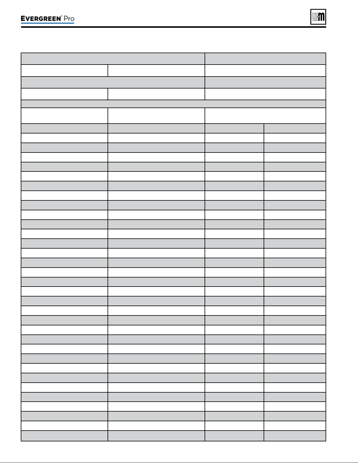
Part number 550-100-211/0122
– 132 –
Boiler Model / Series EVG ________ / Series _______ Date Installed: ___________________
CP Number: __________________ Fuel Type: Natural___ LP___ BTU Input: ____________
Flame signal on control display at HIGH re: _________________ Flame signal on control display at LOW re: ____________
Was venturi changed? YES___ NO___ Was gas valve throttle adjusted? YES___ NO___ Was gas valve offset adjusted? YES___ NO___
Boiler Settings Network Settings Priority 1 Settings
Boiler Model: EVG ______ Boiler Address: ____ System Type: ___________
Control Type: _________ Net Max On Time: _____Min Target Mod Sensor: ___________
Altitude: _________Feet Net Min On Time: _____Min Target Adjust: ___________
LP Gas: YES___ NO___ Max Rate On Net: _____% Supply Max: ___________˚F
ODT Sensor Exempt: YES___ NO___ Min Rate On Net: _____% Supply Min: ___________˚F
Manual Reset High Limit Temp: ____˚F Rotation & Sequence OD Reset Max: ___________˚F
WWSD Temp: ____˚F Sequence Type: ______ OD Reset Min: ___________˚F
Adjust Outdoor: ____˚F Base Rate High: _____% Volts For Max: ___________ V
Circulator Exercising Base Rate Low: _____% Volts For Min: ___________ V
Circulator 1: ON___ OFF___ Boiler Rotation Type: _________ Boost Time: ___________ Mins
Circulator 2: ON___ OFF___ Rotate Frequency: ____Days System Off Diff: ___________˚F
Circulator 3: ON___ OFF___ Force Lead Rotation: YES or NO System On Diff: ___________˚F
Boiler Circ: ON___ OFF___ Modbus Settings Add BLR Diff: ___________˚F
Freeze Protection Enable: YES___ NO___ Drop BLR Diff: ___________˚F
Circulator 1: ON___ OFF___ Address: __________ Mod Delay Time: ___________ Mins
Circulator 2: ON___ OFF___ Parity Bit: __________ Stabilization Time: ___________ Mins
Circulator 3: ON___ OFF___ Baud Rate: _________bps Add Delay Time: ___________Sec
Boiler Circ: ON___ OFF___ Stop Bit: YES___ NO___ Drop Delay Time: ___________Sec
Assign Inputs Max BLR Temp: ___________˚F
Input 1: Priority___ Aux___ OFF___ Boiler On Diff: ___________˚F
Source: TT1 ___ OR 0-10V ___ Boiler Off Diff: ___________˚F
Input 2: Priority___ Aux___ OFF___ Max On Time: ___________ Mins
Input 3: Priority___ Aux___ OFF___ Run Boiler Pump: YES___ NO___
Run Aux Pump/Output: YES___ NO___
Pre Pump: ___________Sec
Post Pump: ___________Sec
Max Rate: ___________%
Min Rate: ___________%
Max System BTUs: __________ MBUTs
Min Boilers On: ___________
Additional Heat Demand: 1st___ 2nd___ OFF__
Response Time: ___________ Mins
220 /29 9/3 00 /39 9
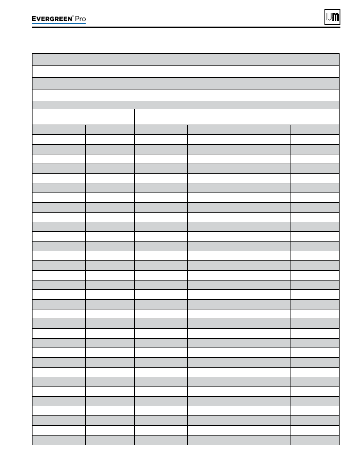
Part number 550-100-211/0122
– 133 –
220 /29 9/3 00 /39 9
Flame signal on control display at HIGH re: _________________ Flame signal on control display at LOW re: ____________
___________˚F
___________˚F
Manual Reset High Limit Temp: ____˚F ___________˚F
WWSD Temp: ____˚F ___________˚F
Adjust Outdoor: ____˚F
___________˚F
___________˚F
___________˚F
Freeze Protection ___________˚F
Stabilization Time:
___________˚F
___________˚F
___________˚F
CO2 @: High Fire______% Low Fire______%
CO@: High Fire _____ ppm Low Fire _____ ppm
Natural Gas / LP input rate measured: HIGH ______ CFH / LOW________ CFH
Priority 2 Settings Priority 3 Settings
Priority 4 Settings
(Multi BLR Sys Only)
System Type: ___________ System Type: ___________ System Type: ___________
Target Mod Sensor: ___________ Target Mod Sensor: ___________ Target Mod Sensor: ___________
Target Adjust: ___________ Target Adjust: ___________ Target Adjust: ___________
Supply Max: ___________˚F Supply Max: ___________˚F Supply Max: ___________˚F
Supply Min: ___________˚F Supply Min: ___________˚F Supply Min: ___________˚F
OD Reset Max: ___________˚F OD Reset Max: ___________˚F OD Reset Max: ___________˚F
OD Reset Min: ___________˚F OD Reset Min: ___________˚F OD Reset Min: ___________˚F
Volts For Max: ___________ V Volts For Max: ___________ V Volts For Max: ___________ V
Volts For Min: ___________ V Volts For Min: ___________ V Volts For Min: ___________ V
Boost Time: ___________ Mins Boost Time: ___________ Mins Boost Time: ___________Mins
System Off Diff: ___________˚F System Off Diff: ___________˚F System Off Diff: ___________˚F
System On Diff: ___________˚F System On Diff: ___________˚F System On Diff: ___________˚F
Add BLR Diff: ___________˚F Add BLR Diff: ___________˚F Add BLR Diff: ___________˚F
Drop BLR Diff: ___________˚F Drop BLR Diff: ___________˚F Drop BLR Diff: ___________˚F
Mod Delay Time: ___________ Mins Mod Delay Time: ___________ Mins Mod Delay Time: ___________Mins
Stabilization Time: ___________ Mins Stabilization Time: ___________ Mins Stabilization Time: ___________Mins
Add Delay Time: ___________Sec Add Delay Time: ___________Sec Add Delay Time: ___________Sec
Drop Delay Time: __________Sec Drop Delay Time: ___________Sec Drop Delay Time: ___________Sec
Max BLR Temp: __________˚F Max BLR Temp: ___________˚F Max BLR Temp: ___________˚F
Boiler On Diff: __________˚F Boiler On Diff: ___________˚F Boiler On Diff: ___________˚F
Boiler Off Diff: __________˚F Boiler Off Diff: ___________˚F Boiler Off Diff: ___________˚F
Max On Time: __________ Mins Max On Time: ___________ Mins Min On Time: ___________ Mins
Min On Time: __________ Mins Run Boiler Pump: YES___ NO___ Run Boiler Pump: YES___ NO___
Run Boiler Pump: YES___ NO___ Run Aux Pump/Output: YES___ NO___ Run Aux Pump/Output: YES___ NO___
Run Aux Pump/Output: YES___ NO___ Pre Pump: ___________Sec Pre Pump: ___________Sec
Pre Pump: ___________Sec Post Pump: ___________Sec Post Pump: ___________Sec
Post Pump: ___________Sec Max Rate: ___________% Max Rate: ___________%
Max Rate: ___________% Min Rate: ___________% Min Rate: ___________%
Min Rate: ___________% Max System BTUs: __________ MBUTs Max System BTUs: ___________ MBUTs
Max System BTUs: ___________MBUTs Min Boilers On: ___________ Min Boilers On: ___________
Min Boilers On: ___________ Additional Heat Demand: 1st___ 2nd__ OFF__ Additional Heat Demand: 1st___ 2nd__ OFF__
Additional Heat Demand: 1st___ 2nd__ OFF__ Response Time: ___________ Mins Response Time: ___________ Mins
Response Time: ___________Mins

Part number 550-100-211/0122
– 134 –
220 /29 9/3 00 /39 9

Part number 550-100-211/0122
– 135 –
220 /29 9/3 00 /39 9

136
220 /29 9/3 00 /39 9